1
BEng Final Year Project Report
School of Engineering and Technology
BACHELOR OF ENGINEERING DEGREE WITH HONOURS IN ELECTRICAL
AND ELECTRONIC ENGINEERING
Final Year Project Report
School of Engineering and Technology
University of Hertfordshire
INTERHOME: EXTENSION ON ASSISTED LIVING
Report By
MD IBNA ZAMAN
Supervisor
JOHANN SAIU
14th April 2010
Md Ibna Zaman/ InterHome-Extension on Assisted Living
School of Engineering and Technology
BEng Final Year Project Report
DECLARATION STATEMENT
I certify that the work submitted is my own and that any material derived or quoted from
the published or unpublished work of other persons has been duly acknowledged (ref.
UPR AS/C/6.1, Appendix I, Section 2 – Section on cheating and plagiarism)
Student Full Name: MD IBNA ZAMAN
Student Registration Number: 07134530
Signed: …………………………………………………
Date: 14 April 2010
Md Ibna Zaman/ InterHome-Extension on Assisted Living
i
School of Engineering and Technology
BEng Final Year Project Report
ABSTRACT
This report describes the project work which is based on providing supervision for
assisted living residence such as disable or elder people. Here deals to build an
embedded device for continuous monitoring their health condition, movement and send
data through wireless communication system to the service provider or smart home
device.
On the base of this project, proposed a wearable wrist belt for 24 hours patient
monitoring service. This report indicates the working stages undertaken to design,
development and implementation of the device. It also provides the workout on project
management including project time plan and resource analysis.
Finally the report highlights the commercial aspects, product marketability and future
development for more successful implementation in different areas of assistive living.
Md Ibna Zaman/ InterHome-Extension on Assisted Living
ii
School of Engineering and Technology
BEng Final Year Project Report
ACKNOWLEDGEMENTS
I would like to thank my supervisor Mr. Johann Siau for his guidance and assisted me
during the whole project. During my project when I lost the way, he gave me proper
direction of progress. Once again, I would like to thank him for his moral support and
giving me his valuable time as well as encourage me to work best.
I would like to thank Mr. John Wilmot and Mr. Ian Munro for their logistic support as
well as the School of Engineering and Technology for funding on this project.
Finally I would like to thank my parents and my friends for their support.
Md Ibna Zaman/ InterHome-Extension on Assisted Living
iii
School of Engineering and Technology
BEng Final Year Project Report
TABLE OF CONTENTS
DECLETATION STATEMENT.................................................................................i
ABSTRACT..............................................................................................................ii
AKNOWLEDGEMENTS...........................................................................................iii
TABLE OF CONTENTS ..........................................................................................iv
LIST OF FIGURES...................................................................................................vi
LIST OF TABLES.....................................................................................................vii
GLOSSARY..............................................................................................................viii
1. INTRODUCTION..........................................................................................1
1.1 PROJECT BACKGROUND....................................................................1
1.2 RELATED WORKS.................................................................................2
1.3 AIMS AND OBJECTIVES.......................................................................3
1.4PROJECT FEASIBILITY..........................................................................5
1.5 REPORT GUIDELINE.............................................................................5
2. SUBJECT REVIEW......................................................................................6
2.1 HOME AUTOMATION............................................................................6
2.2 SMART HOME........................................................................................7
2.3 INTERHOME...........................................................................................8
2.4 I 2 C BUS.................................................................................................8
2.5 .NET MICRO FRAMEWORK..................................................................10
2.6 XBEE COMMUNICATION SYSTEM.....................................................10
3. PROJECT DESIGN AND DEVELOPMENT................................................12
3.1 SYSTEM OVERVIEW.............................................................................12
3.2 SYSTEM DESIGN..................................................................................14
3.2.1 MICROCONTROLLER UNIT (Meridian/P)...........................14
3.2.2 SENSORS UNIT....................................................................16
3.2.3
COMMUNICATION UNIT...................................................19
3.2.4
POWER MANAGEMENT UNIT..........................................21
Md Ibna Zaman/ InterHome-Extension on Assisted Living
iv
School of Engineering and Technology
BEng Final Year Project Report
4. IMPLEMENTATION.....................................................................................25
4.1 HARDWARE IMPLEMENTATION.........................................................25
4.1.1 BREADBOARD DESIGN........................................................25
4.1.2 PCB DESIGN...........................................................................27
4.2 SOFTWARE IMPLEMENTATION..........................................................30
4.2.1 TEMPERATURE SENSOR AND ACCELEROMETER..........32
4.2.2 PANIC BUTTON......................................................................37
4.2.3 EMBEDDED DEVICE..............................................................38
4.2.4 I2C-BUS OPERATION............................................................39
4.2.5 SERIAL PORT.........................................................................40
5. TESTING AND RESULT ANALYSIS..........................................................40
5.1 HARDWARE...........................................................................................40
5.2 SOFTWARE............................................................................................42
5.2.1 OBSERVATIONS FOR TEMPERATURE SENSOR
AND ACCELEROMETER.......................................................44
5.2.2 OBSERVATION OF PANIC BUTTON................................... 46
5.2.3 OBSERVATION OF DATA TRANSMISSION........................ 47
6. PROJECT MANAGEMENT........................................................................49
6.1 TIME MANAGEMENT............................................................................49
6.2 RESOURCE ANALYSIS.........................................................................50
6.3 RISK ASSESMENT................................................................................50
7. CONCLUSIONS...........................................................................................51
7.1 COMMERCIAL AND SOCIAL ASPECTS..............................................51
7.2 FUTURE DEVELOPMENT.....................................................................53
REFERENCES.................................................................................................54
BIBLIOGRAPHY..............................................................................................58
APPENDIX.......................................................................................................58
Md Ibna Zaman/ InterHome-Extension on Assisted Living
v
School of Engineering and Technology
BEng Final Year Project Report
LIST OF FIGURES
Figure 2-1: Smart Home [16] .....................................................................................8
Figure 2-2: Devices connected with Microcontroller using I2C bus..........................9
Figure 2-3: Communication between UART pin of Microcontroller
and XBee Module [25]............................................................................11
Figure 3-1: System Operation of Wrist Belt and
existing Smart Home System (InterHome).............................................13
Figure 3-2: Block diagram of the wrist-belt...............................................................14
Figure 3-3: (a) View of Meridian/P (b) Available connection [28]
(c) Schematic Pin notified Expansion 2 (EXP2) of Meridian/P [28].........15
Figure 3-4: (a) View of DS1624 (b) Schematic Pin outline of DS1624 [29]
(c) Connection of DS1624......................................................................17
Figure 3-5: (a) View of LIS302DL (b) Schematic pin outline of LIS302DL [30]
(c) Connection of LIS302DL...................................................................18
Figure 3-6: (a) Proposed panic button (b) Schematic of Panic Button
(c) Connection with Meridian/P............................................................19
Figure 3-7: (a) View of XBee Module (b) Schematic and Pin identification [25]
(c) Connection of XBee...........................................................................19
Figure 3-8: (a) Schematic of DC-DC convertor (b) Schematic of MCP73837
(c) USB and AC-DC adaptor socket.......................................................21
Figure 3-9: Schematic of whole Power Management Unit......................................22
Figure 3-10: (a) The schematic of the proposed wrist-belt
(b) Pin outline of each component.......................................................24
Figure 4-1: (a) View of Breadboard and (b) its operation [37]...................................25
Figure 4-2: The concept for Hardware design..........................................................26
Figure 4-3: Breadboard design of the proposed wrist-belt........................................27
Figure 4-4: (a) PCB without Power Management Unit-37.4 mm
(b) PCB with Power Management Unit-48 mm......................................30
Figure 4-5: New Project window for creat new porject.............................................31
Figure 4-6: Solution Explorer window.......................................................................31
Figure 4-7: Writing references in main programming code.....................................32
Figure 4-8: (a) Code for DS1624 (b) Code for LIS302DL.........................................32
Figure 4-9: (a) Register declaration of DS1624
(b) Register declaration of LIS302DL.....................................................33
Md Ibna Zaman/ InterHome-Extension on Assisted Living
vi
School of Engineering and Technology
BEng Final Year Project Report
Figure 4-10: Code for inside the memory-block of DS1624.....................................35
Figure 4-11: Code for inside the memory-block of LIS302DL..................................35
Figure 4-12: measurement code for temperature sensor and accelerometer.........37
Figure 4-13: Programming code for Panic Button....................................................38
Figure 4-14: A part of code for embedded device in Progarm.cs.............................38
Figure 4-15: Code for output of the embedded device.............................................39
Figure 4-16: Code from I2C.cs..................................................................................39
Figure 4-12: Code written in main function declares XBee.......................................40
Figure 5-1: Hardware Testing....................................................................................41
Figure 5-2: XBee USB Adaptor [40]...........................................................................42
Figure 5-3: (a) Direction of G-force of body in vertically
(b) Direction of G-force in transversely [34]..............................................43
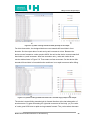
Figure 5-4: (a) Data of normal movement (b) Graph of the normal movement........44
Figure 5-5: (a) Data of falling towards forward (b) Graph of the output....................45
Figure 5-6: (a) Data of falling towards left-hand side in forward way
(b) Graph of the output............................................................................45
Figure 5-7: (a) Data of falling towards right-hand side in front way
(b) Graph of the output...........................................................................46
Figure 5-8: Operation of Panic Button......................................................................47
Figure 5-9: PuTTy window........................................................................................48
Figure 5-10: Data transmission in running session of PuTTY by using COM4........49
Figure 6-1: Summery of proposed the project plan...................................................50
LIST OF TABLES
Table 2-1: Device terminology in 𝐈 𝟐 𝐂 bus [22]..........................................................9
Table 2-2: Specification difference between XBee and XBee-PRO [25]...................11
Table 3-1: UART pins description of Meridian/p [28].................................................16
Table 4-1: Register CTRL_REG1 description [30].....................................................36
Md Ibna Zaman/ InterHome-Extension on Assisted Living
vii
School of Engineering and Technology
BEng Final Year Project Report
GLOSSARY
MEMS- Micro Electro-Mechanical systems.
GPRS- General Packet Radio Service
UMTS- Universal Mobile Telecommunications System
PDA- Personal Digital Assistant.
SPI- Serial Peripheral Interface
IP- Internet Protocol
CPU- Central Processing Unit
SDA- Serial Data Address
SCL- Serial Clock Line
pF/kF- pico farads / kilo farads
LR-WPAN- low-rate wireless personal area networks
DSSS- Direct Sequence Spread Spectrum.
UART- Universal Asynchronous Receive/Transmitters
CTS/ RTS - Clear to Send / Request to Send
GSM- Global System for Mobile Communications
GPIO- General Purpose Input /Output
Li-ion- Lithium-Ion
DIP- Dual In-line Package
MISO - Master Output/Slave Input
MISO- Master Input/ Slave Output
SDO- Serial Data Output.
AC/DC- Access Current /Direct Current
MSOP- Mini Small Outline Package,
USB- Universal Serial Bus
FPGA- field-programmable gate array
PCB- Printed Circuit Board
Md Ibna Zaman/ InterHome-Extension on Assisted Living
viii
School of Engineering and Technology
BEng Final Year Project Report
1 INTRODUCTION
The development in a residential network for smart healthcare is broad up a new
horizon for continuous long-term monitoring of assisted and independent-living
residents. The introduction part provides the project background, some related works,
aims and objectives as well as chapter guideline of the report.
1.1 PROJECT BACKGROUND
Assisted living residences are referred to as who requires assistance for daily living
activities. Additionally the residence frequently is coordinated with third party healthcare
and service providers on the resident's behalf. Assisted living emerged in the 1990's as
the next step of continuing care for people who cannot live independently in a private
residence, but who also do not require the 24-hour medical care provided by a nursing
home. [2]
The implementation of assisted living technology exists today since 1980s when
microelectromechanical systems (MEMS) have been used in the medical industry for a
variety of silicon pressure, accelerometer, and custom microstructure applications. [1]
As the world‟s population ages, those suffering from diseases of elderly and disability
are increasing day by day. So the raising healthcare costs and the increasing elderly
population are placing a strain on current health care service. Elderly patient and
disable, especially those with chronic conditions, requires long-term monitoring. By
using modern home automation system provides those 24 hours monitoring and
continuous care in home environment. Different wearable sensors build a sensor
network in the device for measuring various data and send to receiver by using
wireless communication. This system can be utilized in individual patient home or care
home system. So the service providers can monitor a number of patients at a time.
Nowadays the care home service providers are using assistive living technology for
providing better service.
The sensor network system integrates into a device. Some wearable on the patient and
some placed inside the living space such as bed, wall etc. They together inform the
healthcare provider about the health status of the resident. Data is collected,
aggregated, pre-processed, stored, and acted upon using a variety of sensors and
devices. Data can be sending through power line, radio frequency (RF), Wi-Fi, inferred
or Bluetooth etc.
Md Ibna Zaman/ InterHome-Extension on Assisted Living
1
School of Engineering and Technology
BEng Final Year Project Report
1.2 RELATED WORKS
With the population is growing older, the demand for healthcare is growing rapidly. To
meet the demand for more healthcare people are starting to look for new healthcare
technology in less expensive way. Healthcare for elderly people is a huge area with lots
of potentials. So many universities and companies are doing different kind of research
within the area.
Imperial Collage of London has developed UbiMon. It is aimed at addressing general
issues related to using wearable and implantable sensors for distributed mobile
monitoring. [6] UbiMon is a designed device for wearable communicator performing
multi-sensor interfacing, automated techniques for integrating multi-sensory data
leading to an intervention strategy as well as preliminary clinical evaluation for
management of patients with ischemic and arrhythmic heart disease called
Cardiovascular disease. [6]
CodeBlue and Mercury are wireless sensor network for medical care. Both are
developed by Harvard University. The applications of wireless sensor network
technology to a range of medical applications, including pre-hospital and in-hospital
emergency care, disaster response, and stroke patient rehabilitation.[3] Mercury
includes long sensor node lifetime, autonomous operation, and the need for the system
to automatically tune its behaviour in response to fluctuations in radio bandwidth and
energy availability.[4] An earlier version of Mercury (v1.0) is used on the patient of
Parkinson (Motor neuron disease) and Epilepsy (Brain Disease). [4]
MIT researched on wireless blood pressure monitor system. They have built a
wearable blood pressure sensor that can provide continuous, 24-hour monitoring. [11]
This device monitors patient high blood pressure and sends data through radio
frequency. It could help diagnose hypertension, heart disease as well. [11]
Microsoft Corporation researched on HealthGear. It is a real-time wearable system for
monitoring, visualizing and analyzing physiological signals. [12] It is set of non-invasive
physiological sensors which wirelessly connected via Bluetooth to a cell phone which
stores, transmits and analyzes the data. [12]
BT (British Telecom) and Anchor Trust developed together a system that is capable of
monitoring people's movements and looking for deviations from a 'normal' pattern of
behaviour that may indicate a potential problem. [9]
Md Ibna Zaman/ InterHome-Extension on Assisted Living
2
School of Engineering and Technology
BEng Final Year Project Report
European Commission is funded on mobile healthcare project called Mobihealth. It is
the implementation of GPRS or UMTS services in healthcare. [10] The system allows
patients to be fully mobile whilst undergoing health monitoring. The patients wear a
lightweight monitoring system - the MobiHealth BAN (Body Area Network) - which is
customized to their individual health needs. [10] So it helps to monitor of patients status
and progress as well as quick handling of emergency situations. [10]
Royal Philips Electronics has introduced Lifeline with AutoAlert, a medical alert service
which is able to detect falls and call for help for elder people. The alert system consists
of pendant-style button. The button is worn around the neck which can be pressed to
call for help at any time. [7]
Corventis is maker of wireless CHF (Congestive Heart Failure) monitoring devices that
measure heart rate, heart rate variability, respiratory rate, fluid status and activity. [8]
Piix designed to remote wireless monitoring technology in proactively managing heart
failure patients and reducing hospital readmissions. [8]
CardioNet provides a remote heart monitoring system where ECG signals are
transmitted to a PDA (Personal Digital Assistant) and then routed to the central server
by using the cellular network. [5]
1.3 AIMS AND OBJECTIVES
The main aim of this project is to design a device which helps assisted living by sending
data such as heart beat, pulse reading, blood pressure, temperature or movement etc.
through various data transmitting media named Wi-Fi, Bluetooth, Inferred, Radio
Frequency or power transmission line etc. Design sensors networking and embedded
device which have made it feasible to monitor and provide medical and other assistance
to people in their homes. The designed device aims to send data to the existing Smart
Home System (InterHome).
Md Ibna Zaman/ InterHome-Extension on Assisted Living
3
School of Engineering and Technology
BEng Final Year Project Report
The main object can be divided into two parts. First part is to work on hardware and
second part is software.
Choose particular sensor and connection media for those.
Here choose the LIS302DL accelerometer for movement monitoring and
DIS1624 temperature sensor. Both sensors are connectable with I 2 C-Bus and
SPI. Here sensors are connected with I 2 C-Bus of Meridian/P microcontroller.
The details explanation I 2 C-Bus and Meridian/P is give in section 2.4 and 3.2.1.
Choose a communication medium.
This is very essential part for this project. As it will decide how the device is
communicate with the smart home device. There are many ways to transmit the
data through device but here prefer wireless communication via radio frequency
(RF). So the device designed with XBee communication system. The details of
XBee communication system is given in section 2.6.
Build the hardware design in breadboard by using required components.
At first work on paper based designed then work on breadboard design. So
after getting all components, designed the system on breadboard. Some
components need adaptor to work on breadboard like XBee, IC of MSOP (Mini
Small Outline Package) pin. Explanation of connection of breadboard is given in
section 4.1.1.
By using C# or Java write the code for sensor network and microcontroller.
For this embedded device using Meridian/P microcontroller. So write the
programming code for device in C# on .Net Microframework. In section 2.5 details
on .NET Microframework is explained.
Test the whole designed device to the assisted controller.
After completing the whole design and programming, test the whole system.
Sometimes requires modification in hardware design and programming code.
The result analysed form the output of the system. The detail provides in
Chapter 5.
Md Ibna Zaman/ InterHome-Extension on Assisted Living
4
School of Engineering and Technology
BEng Final Year Project Report
1.4 PROJECT FEASIBILITY
Before working on this project, the feasibility report is generated. That carried out to
determine the working stages, outline design, proposal in terms of software and
hardware requirements to handle the completion of the project
Due to recent advances in sensor networks and embedded technologies, designed
health monitoring devices have become practically feasible.
1.5 REPORT GUIDELINE
This report provides information on the design and development of assistive living
device. A brief outline of the report is given below.
Chapter 1: This chapter introduces with assisted living technology and project
background. Some related research from different universities and companies as well as
aims and objectives also discussed. It includes the brief description of the organisation of
report and project feasibility.
Chapter 2: All background information which is related with this project has been
discussed in this section. It covers home automation, InterHome, .NET
Microframework, I 2 C Bus and XBee communication system.
Chapter 3: This chapter discusses on whole system overview and design. Here shows
how the project is designed and forwarded to the development. Also include block
diagram of the project and the schematic diagram of the design. Design of each part
has been explained in this section. The connections between Meridian/P and all other
components are shown here. The components include sensor unit, communication unit
and power management unit.
Chapter 4: Discussed on hardware and software implementation in this section. PCB
design and Breadboard design are introduced in hardware implementation. The
programming code of each component and whole system is explained in software
implementation section.
Chapter 5: The output result is analysed in this chapter. The output from
accelerometer and temperature sensor is discussed. Analysis of the result is explained
in different situations.
Md Ibna Zaman/ InterHome-Extension on Assisted Living
5
School of Engineering and Technology
BEng Final Year Project Report
Chapter 6: Project management is very essential part in project handling. Time
management, resource analysis and risk assessment have been briefly discussed in
this chapter.
Chapter 7: This chapter concludes the whole project work. Here discuss on the aims
that are given in section 1.3. Also evaluates if any additional objective is done for
project work. Commercial aspects of assistive living technology are discussed in this
chapter. Future development and recommendations are provided here for more useful
applications.
2 SUBJECT REVIEW
Due to high increase the number of aging population expresses that the automatic
home monitoring will represent major challenge near future. Advances in
communication system, sensors, and embedded devices have made possible to
monitor and provide medical and other assistance to assisted people in their homes.
With the aid of modern technology make the home more comfortable and caring for
elder people. Aging populations will be benefitted from reduced costs and improved
healthcare through assisted living based technologies. These systems provide more
usability, reliability, and security. This is extensible system that combines software and
hardware. The system can also provide information to diverse clinicians on 24 hours
based. This report presents the system architecture for extension on assisted living that
allows independent, secure, low-cost and emergency detection for assistive people.
The approach is based on XBee communication system. The designed device will send
data to smart home system. Additionally a server can be connected that collects and
maintains assisted persons' records. The designed system shows the feasibility and
new opportunity of an approach to assisted living systems.
2.1 HOME AUTOMATION
Home automation is becoming more popular around the world and is becoming a
common practice. The process of home automation works by making everything in the
house automatically controlled using technology to control and do the jobs that would
normally do manually. [13] Nowadays home automation takes care of a lot of different
activities in the house. The term may be used in contrast to the more mainstream
"building automation", which refers to industrial uses of similar technology, particularly
the automatic or semi-automatic control of lighting, doors and windows, heating,
Md Ibna Zaman/ InterHome-Extension on Assisted Living
6
School of Engineering and Technology
BEng Final Year Project Report
ventilation and air conditioning, and security and surveillance systems. [14] Home
automation technique can be applied in the control of home entertainment systems,
houseplant watering and kitchen applications. There are four types of home control
system named power line carrier system, wireless system, and hardwired system and
IP control. [15] Power line carrier system is X10 based system. It operates through
existing wire lines. Wireless system is based on the data transmission through radio
frequency technology. Hardwired system introduces systems which can operate over
high-grade communications cable. IP control means that house operates like its own
secure Internet via a Web server, or a computer network. [15] For this project wireless
system is used but IP (Internet Protocol) control system can be applicable in future
application.
Now home automation focuses on making home for the elderly and disabled more safe
and comfortable. Here using home automation system to monitor their daily activities.
This system provides more options for the assistive people who would prefer to stay in
the comfort of their homes rather than move to a healthcare facility. Home automation
is being implemented for assistive living in order to offer more independence and
safety.
2.2 SMART HOME
The home which is operating through automated system is called Smart Home. Smart
Home designs in the concept of Home Automation. The main idea of home automation
is to employ sensors and control systems to monitor a dwelling, and accordingly adjust
the various mechanisms that provide heat, ventilation, lighting, and other services. [17]
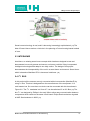
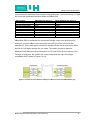
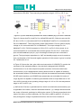
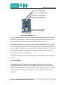
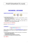
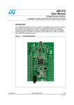
In Figure 2-1 shows a house is in the concept of Smart Home where every system is
control and monitoring. By definition, a dwelling incorporating a communications
network that connects the key electrical appliances and services, and allows them to
be remotely controlled, monitored or accessed. [18]
This can provide more control and security in different home applications. It provides
services in six main areas environmental, security, home entertainment, domestic
appliances, information and communication and health care. [18] The assistive people
can be monitored 24 hours basis in homely environment. Smart home system provides
medication reminder, health monitoring, indication of any emergency situations like
fallen. [18]
Md Ibna Zaman/ InterHome-Extension on Assisted Living
7
BEng Final Year Project Report
School of Engineering and Technology
Figure 2-1: Smart Home [16]
Smart home technology is real, and it's becoming increasingly sophisticated. [19] The
idea of Smart Homes carries a vital role in the planning of future housing-based models
of care.
2.3 INTERHOME
InterHome, an existing smart home concept which has been designed to test and
demonstrate how much greener and secure our homes could be if they incorporated
intelligent technologies that adapt to our daily routine. The design of this project
demonstrates the interoperability of the unit in a smart home environment. Smart Home
which is based on Meridian CPU is known as InterHome. [20]
2.4 𝐈𝟐 𝐂 BUS
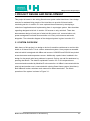
In this project all the sensors are only connected with microcontroller (Meridian/P) by
using I 2 C bus. This bus is designed from the manufactures of the component. It is
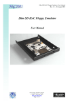
multi-master bus. So more than one device can be connected with this bus shows in
Figure 2-2. The I 2 C translates into "Inter IC” can be called as IIC or I2C Bus. [21] The
bus I 2 C as designed by Philips in the early '80s to allow easy communication between
components which reside on the same circuit board. Philips Semiconductors migrated
to NXP Semiconductor in 2006. [21]
Md Ibna Zaman/ InterHome-Extension on Assisted Living
8
School of Engineering and Technology
BEng Final Year Project Report
Figure 2-2: Devices connected with Microcontroller using I2C bus
I 2 C -Bus requires two bus lines; a serial data line (SDA) and a serial clock line (SCL).
[22]
It is a multi-master bus including collision detection and arbitration to prevent data
corruption if two or more masters simultaneously initiate data transfer. [22] It is serial
and 8-bit oriented and bidirectional as well. The data transfers can be made at up
to100 kbit/s in the standard/ regular mode or up to 400kbit/s in the fast mode. [22] But
now a high speed 3.4 Mbit/s available. [21] This bus can be connected by wires. The
serial data (SDA) and serial clock (SCL) carry information between the devices
connected to the bus. Every single device is recognized by a unique address. [22]
The SDA and SCL lines are pulled up to the supply voltage (3.3V to 5V) with a pull-up
resistor. [23] As well as the number of devices connected to the bus is only limited by
the bus capacitance is considered of 400pF. [23] This bus is low power consumption
and flexible to use.
Here the sensors are connected with microcontroller by using I 2 C bus. The device can
operate as either a transmitter or receiver, depending on the function of the device. In
addition to transmitters and receivers, devices can also be considered as masters or
slaves during data transmission. [23] A master is the device which initiates a data
transfer on the bus and generates the clock signals to permit that transfer. At that time,
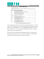
any device addressed is considered a slave. [23] Table 2-1 shows its operation. In
Section 4.2.4 the operation of this bus is given in details.
Term
Transmitter
Receiver
Master
Slave
Description
The device which sends data to the bus
The device which receives data from the bus
The device which initiates a transfer. Generates clock signals and
terminates a transfer.
The device addressed by master
Table 2-1: Device terminology in 𝐈𝟐 𝐂 bus [22]
Md Ibna Zaman/ InterHome-Extension on Assisted Living
9
School of Engineering and Technology
BEng Final Year Project Report
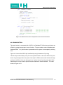
2.5 .NET MICRO FRAMEWORK
In this project, an embedded device is designed by using .NET Micro Framework. It
does not require an operating system due to have features to operate like a subset of
the operating system. [47] The .NET Micro Framework does not operate like traditional
operating system and it was developed by Microsoft Research. [47] It works as a
bootable run time and its platform can also run in 32-bit processor. [47] The .NET Micro
Framework gives user a flexible and powerful for creating an embedded device. It is
more applicable in small technology. That‟s why it was known as SPOT (Small
Personal Objects Technology). [47]
The .NET Micro Framework helps to write code more reusable way. This can also
extend and modify any existing code easily. It has high level of tools and libraries which
help to design the embedded device quickly. The implementation system is very easy
and more flexible. Here the Meridian/P is connected with other components. The
programming for this project is written in C# in .NET Micro Framework platform.
2.6 XBEE COMMUNICATION SYSTEM
For this project work, build a wireless network by using XBee Modules. The XBee and
XBee-PRO OME RF Modules were engineered to meet IEEE 802.15.4 standards and
support the unique needs of low-cost, low-power wireless sensor networks. [25] IEEE
802.15.4 provides a physical layer of low-rate wireless personal area networks (LRWPAN). [26] This is used due to the lower cost than other wireless communication
system. XBee or XBee-PRO RF Modules has ISM (Industrial, Scientific & Medical)
frequency band of 2.4GHz. [25] It operates in low operating voltage. It provides more
security by using Direct Sequence Spread Spectrum (DSSS). Spread Spectrums
transmit much larger bandwidth than the information bandwidth through the channel.
[27] Each
direct sequence channels has over 65,000 unique network addresses
available in XBee coomunication [25]
Here for wrist belt, using XBee modules of Series1. The device is designed with XBee.
So it will transmit data to another XBee of the exiting Smart Home system. The key
difference between the XBee and XBee-PRO is distance of data transmission. XBee-Pro
has long distance of data transmission. XBee Module of Series 2 needs configuration so
this will provide more security than Series 1. For this project work XBee-PRO can be
Md Ibna Zaman/ InterHome-Extension on Assisted Living
10
BEng Final Year Project Report
School of Engineering and Technology
connected on the belt when requires more range and Series 2 for more security. In Table
2-2 shows the specification between XBee and XBee-PRO.
Specification
Indoor Range
Outdoor Range
Transmit Power Output
Receive Current
Operating Temperature
Serial Interface Data Rate
RF Data Rate
Number of Channels
Operating Voltage
XBee 802.15.4 (Series 1)
Up to 30m
Up to 100m
1mW
50mA
-40°C to 85°C
1200 - 115200 bps
250 000 bps
16 Direct Sequence
2.8V-3.4V
XBee-PRO 802.15.4 (Series1)
Up to 100m
Up to 1500m
60mW
55mA
-40°C to 85°C
1200 - 115200 bps
250 000 bps
12 Direct Sequence
2.8V-3.4V
Table 2-2: Specification difference between XBee and XBee-PRO [25]
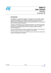
XBee/XBee PRO is interfaced to a host device through a logic-level asynchronous
serial port. [25] Here XBee is connected with the UART pin of the microcontroller
(Meridian/P). So the data which is send from Meridian/P that will be received by XBee.
As well as it will again operate like vice versa. The details connection between
Meridian/P and XBee as well as information of CTS and RTS is given in section 3.2.3.
Through its serial port, the module can communicate with any logic and voltage
compatible UART shows in Figure 2-3. [25]
Figure 2-3: Communication between UART pin of Microcontroller and XBee Module [25]
Md Ibna Zaman/ InterHome-Extension on Assisted Living
1111
School of Engineering and Technology
BEng Final Year Project Report
3 PROJECT DESIGN AND DEVELOPMENT
This project is based on the exiting Smart home system called InterHome. Here design
a device for assisted living people of the InterHome to provide 24 hours health
monitoring service. In section 3.1 have explored the architecture by developing a
collection of applications and implementing them in a prototype system. Also describes
regarding designed wrist belt. In section 3.2 focuses on only wrist belt. There also
demonstrates design of each part of wrist belt like sensor unit, communication unit,
power management unit and microcontroller unit. Every unit connects and works
altogether. The schematic diagram of the designed system is given in section 3.2.
3.1 SYSTEM OVERVIEW
Main theme of this project is to design a device for assistive residences to monitor their
health in 24 hours basis. This is a home automation system. Here propose a wearable
wrist belt which is designed with XBee and sensors. LIS302DL and DS1624 are picked
as accelerometer and temperature sensor. Additionally a panic button is added in the
design for the people who have problems in speech. So they can call for assistance by
pressing that button. The detail is explained in section 3.2.2. All components are
connected and controlled by Meridian/P microcontroller. An XBee is connected with the
wrist belt and another one is connected with existing Smart Home system (InterHome).
Both XBee will make a wireless mesh network for data transmission. The whole
operation of the system is shown in Figure 3-1.
Md Ibna Zaman/ InterHome-Extension on Assisted Living
12
12
School of Engineering and Technology
BEng Final Year Project Report
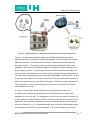
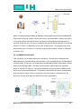
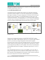
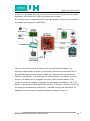
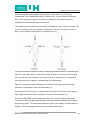
Figure 3-1: System Operation of Wrist Belt and existing Smart Home System (InterHome)
Figure 3-1 shows that an assistive residence of existing InterHome wearing the
designed wrist-belt. The belt is build with XBee Module. It communicates with another
XBee Module which is connected with InterHome. The wrist-belt sends data to the
InterHome system. The InterHome device will send data toward Main Server and
Database. The main server sends data again to the assistive living monitoring centre
and emergency service. So monitoring centre can monitor the assisted residence on
24 hours basis. If any problem occurs then they can provide quick emergency service.
On other hand, the main server can be connected with GSM or GPRS system. For any
occurrence it will inform to the PDA or mobile phone. As well as the assistive person‟s
data can be send 24 hours to the PDA or cell phone. This system is also applicable for
care home service. By using this system care home service providers can monitor
multiple patients at a time.
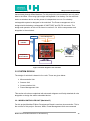
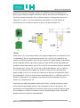
In Figure 3-2 shows the internal combination of the proposed wrist-belt. The
accelerometer LIS302DL and temperature sensors DS1624 are connected with
Meridian/P by using I2C bus. The explanation of this bus is given above in section 2.4.
A panic button is connected with the GPIO (General Purpose Input /Output) pin of the
Meridian/P. The connections between the sensors and panic button are described in
sensor unit section 3.2.2. The collected data will send through the XBee Module which
connected with the UATR pin of the Meridian/P. The microcontroller can receive or
Md Ibna Zaman/ InterHome-Extension on Assisted Living
13
BEng Final Year Project Report
School of Engineering and Technology
transmit data through XBee Modules. For this project the microcontroller can only send
data to the XBee. Here using light weight rechargeable Li-ion battery. So the wrist-belt
works as wireless device and the person is independent to move. So a battery
rechargeable system is designed in the wrist-belt. The Power management unit is
designed with the battery rechargeable IC MCP73837 and DC-DC convertor. The
design and operation of this unit is shown in section 3.2.4. All the components work
altogether in the wrist-belt.
I2C-Bus
Power Management
Accelerometer
LIS302DL
UARTS
Temperature
Sensor-DS1624
XBee Modules
Panic Button
emInterHome
Figure 3-2: Block diagram of the wrist-belt.
3.2 SYSTEM DESIGN
The design of wrist belt is based in four units. Those are given below.
Microcontroller Unit
Sensors Unit
Communication Unit
Power Management Unit
This section all units are explained with schematic diagram and finally attached all units
altogether to design the whole embedded device.
3.2.1 MICROCONTROLLER UNIT (Meridian/P)
For this project Meridian/P Micro Development Board is used as microcontroller. This is
the nucleus of this project. Sensors, XBee, Power Management Unit are connected
Md Ibna Zaman/ InterHome-Extension on Assisted Living
14
School of Engineering and Technology
BEng Final Year Project Report
with this. The whole device is designed on the base of Meridian/P. Meridian/P is
combined with a 100MHz Freescale i.MXS ARM920T based processor, 8MByte of
SDRAM (running at 96MHz), LCD controller, USB function, GPIO, SPI and I2C bus and
serial port. [28] The operating voltage is 5V. It runs on .NET Micro Framework. [28] So
for programming use C# in .NET Micro Framework.
Meridian/P has total 27 pins available for use as general purpose input/output pins but
19 of those pins are labelled as GPIO pins, remaining pin are not supported by .NET
Micro Framework. [28]
Figure 3-3: (a) View of Meridian/P (b) Available connection [28] (c) Schematic Pin notified Expansion 2
(EXP2) of Meridian/P [28]
For this project, design the device by using only expansion 2 (EXP2). Other
connections like LCD Expansion are not used. The pin identification of EXP2 is shown
in Figure 3-3. The pins are notified with blue colour those are used for designing. Rest
of the pins are in black colour those are not used so left open.
Powered 4.3V to 5V DC input voltage through USB port (J1) to run Meridian/P.
Maximum voltage of Input/ Output pin is 3.3V. The typical power consumption of
Meridian/P is only 80mA and operating temperature ratio is 0°C to 70°C. [28] Pin-3
gives +3.3V. So this pin works as supply voltage for all devices. Pin 4 is 0V. So in this
design makes it universal ground for all connections.
Meridian/P supports interfacing to device through the internal I2C bus master or SPI
(Serial Peripheral Interface). [28] But here choose I2C bus to connect with devices.
More information regarding I2C bus is given in section 2.4. So the sensors LIS302DL
and DS1624 are connected with I2C bus. To connect with this bus the device has to
configurable with this bus by manufacture. The base input frequency to the I2C bus is
96MHz. [28] In EXP2, Pin-20 and Pin-22 are signalled as I2C-SDA and I2C-SCL. Serial
Md Ibna Zaman/ InterHome-Extension on Assisted Living
15
BEng Final Year Project Report
School of Engineering and Technology
Clock line (SCL) is used to clock data to the bus and Serial Data line for controller send
or receive data on this line. [28]
If any of I2C or SPI bus does not use then that pins can be worked as input/output pin.
In this design SDA and SCL both are pulled up with 47KΩ resistors.
XBee is connected with UART (Universal Asynchronous Receive/Transmitters) pins for
data communication. Meridian/P has two UART pins. Here using UART1 of EXP2. Both
UART 1 and UART2 are available serial ports (COM1 and COM2) under the .NET
Micro Framework. [28] In this design using all the UART pins of EXP2. The connections
between URAT pins and XBee are given in details in Section 3.2.3. There are four
UART pins are available in Meridian/P EXP2. A brief description and pin location is
given in Table 3-1.
Signal
UART1-TXD
UART1-RTS
UART1-RXD
UART1-CTS
Pin Location
EXP2- Pin 24
EXP2- Pin 26
EXP2- Pin 28
EXP2- Pin 30
Description
Transmitting data line for UART.
Input line to the Meridian/P.
Receiving data line for the UART.
Output line from the Meridian/P.
Table 3-1: UART pins description of Meridian/p [28]
3.2.2 SENSORS UNIT
Sensor Unit is combined with two sensors and panic button. This device is designed with
DS1624 temperature sensor and LIS302DL accelerometer. LIS302DL is three-axis
accelerometer and DS1624 is digital temperature sensor. Both are enable to connect
with I2C serial interface. In this section has explained the connections of both sensors as
well as the panic button. Both are using supply voltage and I2C bus from Meridian/P.
Here using DS1624 of 8-pin DIP (Dual In-line Package). DS1624 consists of two
seperate functional units. Those are 256–byte non-volatile 𝐸 2 memory and direct–to–
digital temperature sensor. [29] 𝐸 2 Memory are able to store any information depends
on the user desires such as frequency compensation coefficients and direct to digital
temperature sensor allows the DS1624 to measure the ambient temperature value in a
13–bit word, with 0.03125°C resolution. [29] For this project using direct to digital
function. The temperature sensor and its related registers are accessed through the
2–wire serial interface (I2C bus). [29] In Figure 3-4 shows pins identification and
Md Ibna Zaman/ InterHome-Extension on Assisted Living
16
School of Engineering and Technology
BEng Final Year Project Report
connections of DS1624. The measurring temperature range is -55°C to 125°C. [29]
Figure 3-4: (a) View of DS1624 (b) Schematic Pin outline of DS1624 [29] (c) Connection of DS1624
Figure 3-4 shows that Pin-1and Pin-2 is notified SDA and SCL. Both pins are used for
I2C bus. So Pin-1 is connected with Pin-20 of Meridian/P and Pin-2 is connected with
Pin-22 of Meridian/P. Those are pulled up with 47KΩ resistor. Pin-8 is used for supply
voltage so it is connected with Pin-3 of Meridian/P. The output voltage Pin-3 of
Meridian/P is 3.3V. DS1624 operates in 2.8V to 5.5V. [29] Pin-3 of this sensor is not
connected and Pin-4 is connected with universal ground. Pin-5 to Pin-7, those three
pins are called address input pin. [29] In this design all those pins are connected to
ground. The input/output capacitance is 10pF and standby supply current is maximum
3µA. [29] Operation of I2C bus and register operations for this sensor is given in section
4.2.1 and section 4.2.4.
In Figure 3-5 shows the view, pins outline and connection of LIS302DL.To monitor the
movement of the assisted residence, the wrist-belt is designed with LIS302DL
accelerometer. It is an ultra compact low-power (less than 1mW) three axis linear
accelerometer. [30] It is designed with sensing element which is capable of detecting
the acceleration and an IC interface able to provide the measured acceleration through
I2C/SPI serial interface. [30] LIS302DL has dynamically user selectable full scales of
± 2g/± 8g and it is capable of measuring accelerations with an output data rate of 100
Hz or 400 Hz as well as the operating voltage range is 2.16V to 3.6V and temperature
range is -40°C to 85°C. [30]
„g‟ defines the G-forces or gravitational force which is worked with accelerometer [33] It
is applicable of the earth, it has two remarkable features: (1) It always directed toward
the centre of the earth, and helps in defining the vertical. (2) Directly proportional to the
mass of the body. [32] When stationary, the force felt by earth‟s gravity is 1G, when a
body undergoes a change in speed and direction, then the force increases in
Md Ibna Zaman/ InterHome-Extension on Assisted Living
17
17
School of Engineering and Technology
BEng Final Year Project Report
proportion to the rate of change. [34] Here „G‟ is defined as the acceleration due to
gravity, gives feeling of weight for instance a heavier body has less acceleration. [32]
The body creates acceleration force in different direction, consequently the force is
called Gx,G y and Gz . [32] The measurement information of „G‟ and analysis of
acceleration due to movement is given in detail in Chapter 5 section 5.2.
Figure 3-5: (a) View of LIS302DL (b) Schematic pin outline of LIS302DL [30] (c) Connection of
LIS302DL
It has 8 pins. Pin-1 is connected with 3.3V of supply voltage which is provided from Pin3 of Meridian/P. Pin-2 is connected with ground. Pin-3 is SCL. Pin-4 and Pin-5 are
notified is as MOSI and MISO. Both pins are used for SPI. MISO (Master Output/Slave
Input) and MISO (Master Input/ Slave Output) is used as SDA (Serial Data Address)
and SDO (Serial Data Output). [30] [31] Pin-3 and Pin-4 is connected with SCL and SDA.
Pin-5 leaves open. Pin-5 is CS. This is I2C or SPI mode selection. [30] The value is 1
for I2C mode and 0 for SPI enabled. [30] So due to using I2C bus connected with
supply voltage (3.3V). Pin-7 and Pin-8 is interrupt pin. Both are connected with GPIO
pin of Meridian/P. So Pin-7 and Pin-8 are connected with Pin-17 (GPIO6) and Pin-13
(GPIO2) of Meridian/P. The registers mode and bus interface operation is given in
Section 4.2.1 and Section 4.2.4.
Panic Button is additionally attached with this wrist belt. In design proposed a panic
button which helps assisted people to call for assistance without any speech. This
panic button is more applicable some specific people who are unable or hard to speak
due to disability. In Figure 3-6 shows the view of proposed panic button, schematic
diagram and the connections with Meridian/P.
Md Ibna Zaman/ InterHome-Extension on Assisted Living
18
18
School of Engineering and Technology
BEng Final Year Project Report
Figure 3-6: (a) Proposed panic button (b) Schematic of Panic Button (c) Connection with Meridian/P
Panic button works as a switch. When panic button is pressed then it makes interruption
in the whole system and notified to the InterHome by sending data that assistance is
required. It has two pins. One pin is connected with ground and another pin is connected
with Pin13- GPIO11 of Meridian/P pull up with 47KΩ resistor. The programming of this
panic button given in Section 4.2.2 and the output of panic button is shown in Chapter 5
in Section 5.2.2.
3.2.3 COMMUNICATION UNIT
This unit works only in data transmission operations. The wrist-belt is designed with
XBee Module for communicating with InterHome. It is connected directly with Meridian/P
microcontroller. The sensor unit sends data to the Meridian/P and it sends data to Smart
Home device through XBee. The XBee communication system has been explained
earlier in Section 2.6. Figure 3-7 shows the schematic and pin outlines of XBee as well
as the connections with Meridian/P. The pins are notified with blue colour means those
pins are used for design. Rest of unused pins are connected in a separate hole. So
those pins can be used again for different and future applications.
Figure 3-7: (a) View of XBee Module (b) Schematic and Pin identification [25] (c) Connection of XBee
Md Ibna Zaman/ InterHome-Extension on Assisted Living
19
19
School of Engineering and Technology
BEng Final Year Project Report
XBee Module of Series1 is used in this device. So it was configured from manufacture.
Series 2 needs manually configuration for operation but it provides more security.
Some specifications of XBee Modules have given in Table 2-2.
The operation of this unit is based on data receiving and transmitting. So both
components are operating as a transmitter and a receiver. The data out from XBee
directly enters to Meridian/P. Similarly the data out from Meridian/P directly goes to
XBee. Again the data sends towards XBee Module of InterHome. XBee is connected is
with Meriden/P through UART pins. Table 3-1 provides information regarding UART
pins of Meridian/P.
Pin-1 is connected with the supply voltage 3.3V of Pin-3 in Meridian/P. Pin-10 is
connected with ground. Pin-2 is UART data output pin for XBee. [25] So it is connected
with Pin-28 of Meridian/P. Pin-28 of Meridian/P is UART1-RXD. This is UART data
input pin for Meridian/P. Data received in this pin is processed by internal UART. [28]
In other way, Pin-2 of XBee is UART data input pin. [25] So here makes a connection of
this pin with Pin-24 of Meridian/P. Pin-24 of Meridian/P is notified as UART1-TXD. This
is transmitting data line for UART. [28] So data is transmitted form Meridian/P to XBee.
Pin-9 and Pin-13, both are connected with GPIO pins of Meridian/P. Pin-9 is an input
pin for sleep control line and Pin-13 is an output pin for ON/Sleep mode indicator. [25]
Pin-9 is connected with Pin-21of Meridian/P (GPIO7) and Pin-13 is connected with Pin23 of Meridian/P (GPIO8).
CTS and RTS, Both pins are common in Meridian/P and XBee. CTS means Clear-ToSend and RTS means Ready-To-Send. [25] In Meridian/P, Pin-30 is identified as
UART1-CTS which is an OUTPUT signal from Meridian/P and Pin-26 is notified as
UART1-RST that is an INPUT line to the Meridian/P. [28]
So CTS-pin of XBee is connected with the RTS-pin of Meridian/P. That means data is
flowing from XBee to Meridian/P. In other hand, RTS-pin of XBee is connected with
CTS-pin of Meridian/P. Now the data is moving from Meridian/P towards XBee. This
operation is shown in Figure 2-3.
Here Pin-12 is a digital input/output pin for XBee; notified as CTS. [25] It is connected
with Pin-26 of Meridian/P (UART1-RTS). Pin-16 (RTS) of XBee is connected with Pin30 of Meridian/P (UART1-CTS).
Md Ibna Zaman/ InterHome-Extension on Assisted Living
20
School of Engineering and Technology
BEng Final Year Project Report
Additionally two leads are connected with Pin-13 and Pin-15 of XBee; details are given
in hardware implementation Section 4.1.
3.2.4 POWER MANAGEMENT UNIT
The designed wrist-belt is portable which provides more independent and flexible
movement for assistive residence. So here offers charging system for rechargeable
light weight Li-Ion battery. The power management unit consists of DC-DC converter,
charging unit and Li-Ion battery. The rechargeable battery provides power for the
microcontroller Meridian/P. The testing battery is 3.7V and energy storage capacity is
1230mAH. Figure 3-8 shows the RECOM DC-DC convertor, Schematic of MCP73837
as well as IC placed on MSOP adaptor and schematic USB or AC-DC adaptor.
Figure 3-8: (a) Schematic of DC-DC convertor [36] (b) Schematic of MCP73837 [35] (c) USB and ACDC adaptor socket.
Charging unit is designed with the base on the MCP73837. MCP73837 is battery
charging IC with variable voltage regulation range 4.2V to 4.5 and the supply voltage of
this is 6V. [35] It works as a charge management controller which integrated
autonomous power selection and reverse discharge protection. [35] Autonomous power
selection means it has auto selection mode of power source. By using this IC, battery
can be charged through USB port or AC-Dc adaptor. When both are connected then it
will automatically take power from adaptor. Temperature range of this IC is -40°C t0
85°C. [35]
Here using MCP73837 dimension of 3 mm by 3 mm MSOP. [35] It is very small. To
design on the breadboard, this chip is attached on MSOP adaptor shows in Figure 38(b). Schematic of Power Management Unit is shown in Figure 3-9 which includes DcDC convertor and power source options (USB and Adaptor).
Md Ibna Zaman/ InterHome-Extension on Assisted Living
21
21
School of Engineering and Technology
BEng Final Year Project Report
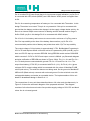
Figure 3-9: Schematic of whole Power Management Unit
Pin-1 is connected with USB port and Pin-2 is connected with AC-DC adaptor socket.
Both are connected with a capacitor 4.7µF with ground. [35] The capacitors are
connected for constant voltage supply.
Pin-3 and Pin-4, both are charge status output pin. [35] In design both are connected
LED with 1kΩ resistor and diode (IN4007). In other way both can be interfaced by
microcontroller. [35] Pin-5 is battery management 0V reference so it is connected to the
ground. [35]
Pin-6 is PROG1 which is for current regulation setting with AC adaptor and Pin-7 is
PROG2 for current regulation setting with USB port. [35] PROG1 is connected with 1kΩ
resistor to the ground. It now works in fast mode If PROG1 is float then the IC works as
standby mode and the resistor value range is 1kΩ to 10Ω. [35] PROG2 is digital input
selection which is for USB port. It works in logic; Low or High. [35]
One unit load charge current when logic Low is selected and five unit loads charge
current if logic High is selected. [35] In this design connected to the ground means logic
Low. Otherwise proposes to connect a switch which helps to operate charging in
different mode.
Md Ibna Zaman/ InterHome-Extension on Assisted Living
22
22
School of Engineering and Technology
BEng Final Year Project Report
Pin- 8 is called PG (Power-Good) that is for input power supply indication. [35] So Pin-8
is connected with LED, diode (IN4007) and 1kΩ resistor. When power is supplied then
is ON.
Pin-9 is for measuring temperature of battery so it is connected with Thermistor. In this
design Thermistor is not used. This pin is very essential. If this pin is connected with
ground then the battery would not be charged. As the supply voltage drains quickly. As
there is an internal 50µA current source for biasing and the thermal resistor range is
2kΩ to 50kΩ. [35] So in this design Pin-9 is connected with 22kΩ resistor.
Pin-10 is for Li-Ion battery and ensures to connect with a minimum of 1μF by pass to
Pin-5 for loop stability at the time of the battery disconnection. [35] So Pin-10 is
connected with positive side of battery and pulled down with 4.7µF for loop stability
The output voltage of Li-Ion battery is approximately 3.75V. But Meridian/P operates in
4.3V to 5V and requires 80mA current as well as it is powered by USB (mini-B). [28] So
here use DC-DC step up convertor RECOM. Using RECOM model number ROXX05S
which converts 3.3V DC to 5V DC and output current is 200mA. [36] Schematic diagram
and pins notification of RECOM are shown in Figure 3-8(a). Pin-1 is –Vin and Pin-3 is –
Vout. So both pins are connected with ground. Pin-2 is +Vin and Pin-4 is +Vout. The
output from battery (3.75V DC) is connected with Pin-2 (+Vin). So Pin-4 (+Vout) gives
minimum 5V Dc output voltage which is connected with Vcc wires of Meridian/P USB
mini-B (red colour). The wires for data are not being used. So the ground of Meridian/P
USB mini-B (Black colour) connects with universal ground. So the wrist-belt runs with
rechargeable battery and works as a portable device. The implementation of this unit
details in breadboard design in Section 4.1.1
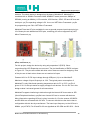
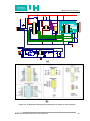
The connections of every unit have described above. All units work simultaneously. In
Figure 3-10 show the schematic diagram of the proposed wrist belt. This diagram
consists of all units where red colour line provides supply voltage of 3.3V DC and black
colour line is universal ground.
Md Ibna Zaman/ InterHome-Extension on Assisted Living
2323
D
N
G
USB
K
1
K
1
Diode2
4.7uF
MCP73837
K
2
2
6
R
4
R
4.7uF
LED2
Md Ibna Zaman/ InterHome-Extension on Assisted Living
Battery
Li-ion
2
C
7
R
Diode1
6
5
4
3.75V
3
C
K
1
7
4
K
1
4.7uF
3
1
D
8
3
3
R
2
1
C
5
R
9
2
LED1
1
2
D
LED3
0
1
1
USB1
IC
Charging
2
1
Adaptor_1
Adaptor
AC-DC
D
N
G
LED6
LED5
XBee
8
2
7
2
0
3
9
2
8
7
12
Header
6
2
5
2
1
1
2
2
2
1
2
1
2
1
1
9
1
0
1
4
2
3
2
DC-DC
3
1
8
6
0
1
0
2
9
1
1
4
1
7
5
9
8
1
7
1
2
5
1
6
4
8
6
1
5
1
3
6
1
5
3
5
4
7
4
1
3
1
4
LED4
7
1
4
2
6
3
6
2
1
1
1
8
1
3
1
7
2
RECOM
5
0
1
9
9
1
2
2
Sensor
8
1
0
3
3
4
8
7
0
2
1
LIS302DL-Motion
1
Sensor
8
R
3
6
5
XBee
DS1624-Temp
LED4
2
4
3
1
2
1
Hole
Exp-2
Meridian/P
SCL
SDA
V-DC
5
SW-PB
VCC
K
7
4
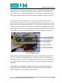
D
N
G
K
7
4
USB-Meridian/P
Res2
Res1
Button
Panic
K
7
4
9
R
2
R
1
R
V-DC
3.3
School of Engineering and Technology
BEng Final Year Project Report
Figure 3-10: (a) Schematic of the proposed wrist-belt (b) Pin outline of each component
24
24
School of Engineering and Technology
BEng Final Year Project Report
4 IMPLEMENTATION
The proposed design is applied on hardware and software implementation for testing
and analysis. After designing on breadboard, the programming code is implemented. So
this section describes hardware and software implementation of the proposed design.
4.1 HARDWARE IMPLEMENTATION
This section provides hardware implementation of the design. In this project at first the
design is tested by using breadboard design. After hardware testing, the programming
code is applied. Breadboard is a prototype for the proposed wrist-belt device. This is
not final product. When the breadboard design is finished then upgrades the design in
PCB (Printed Circuit Board). PCB provides the pattern for manufacturing. So PCB
design includes in hardware implementation describes in Section 4.1.2. .
4.1.1 BREADBOARD DESIGN
Breadboard design gives more flexibility in design. This does not require any soldering.
So the components can be added or removed at any time. The main design can be
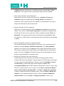
modified at any time. Figure 4-1 shows the view of breadboard.
Figure 4-1: (a) View of Breadboard and (b) its operation. [37]
Breadboards have many small socket holes approximately 0.1" on grid. [37] In the
centre, there is no connection. DIP ICs are placed on it. Two blocks of 5 holes are
placed both sides of the centre line. Those are vertically internal connected which
remarked with blue line in Figure 4-1 (a) and (b). The top and bottom rows both are
connected horizontally. These two lines of top or bottom can be used as positive and
negative polarity of power supply.
Md Ibna Zaman/ InterHome-Extension on Assisted Living
25
School of Engineering and Technology
BEng Final Year Project Report
In Figure 4-1 (b) shows that an IC on the centre line. So it all of its pins are connected
separately. Also shows that a LED is connected with a resistor.
In this project some components requires separate adaptor to place on the breadboard
such XBee and Charging IC (MCP73837).
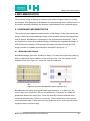
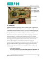
Figure 4-2: The concept for Hardware design
Figure 4-2 shows how the all components are connected with Meridian/P. The
hardware implementation is based on this concept. Sensors are connected with I2C
bus and XBee Module is connected by UART pins. Panic button is connected with
GPIO pin of Meridian/P. The charging unit is connected with Li-Ion battery and power
sources. The battery can be charged in two ways; USB or AC-DC adaptor. From
powers source 5V Dc supplies to charging IC and it charges the battery (3.75V). The
battery is connected with RECOM DC-DC convertor. It converts 3.3V DC to 5V DC. So
the output pin connected with USB mini-B. That USB connects with Meridian/P. So
Meridian/P runs continuously. Breadboard design is shown in Figure 4-3.
Md Ibna Zaman/ InterHome-Extension on Assisted Living
2626
School of Engineering and Technology
BEng Final Year Project Report
Figure 4-3: Breadboard design of the proposed wrist-belt
4.1.2 PCB DESIGN
Nowadays PCB design is widely used in electric connection system in manufacturing.
PCB means Printed Circuit Board. This is design for manufacturing. The Printed Circuit
method was invented by Paul Eisler of the UK in 1943. [38] He provided method on the
conductive pattern of circuit on a layer of copper foil. [38] Later on the multi-layer and
through-hole technique was modified by Hazeltyne of the USA in 1961. [38]
Printed circuit board can be constructed in three different ways; single-sided, doublesided and multi-layers. [38] As well as two other different techniques for electrical
connection in PCB board; through-hole technology and surface-mount technology. [38]
Surface-mount technology applied to reduce the size of every component. In this
project, PCB is designed by using multilayer and through-hole technology.
Here the proposed PCB is designed by using Altium Designer 6.0. This is software for
electronic product development. Altium Designer is used for multi-purpose. Altium
Designer is more applicable for FPGA –level designing, PCB layout designing and
manufacturing.
At first create a PCB project.
New project is created by selecting File>> New >> Project >> PCB Project from
the menu. Project appears in Project browsers. Project name ends with a
Md Ibna Zaman/ InterHome-Extension on Assisted Living
2727
School of Engineering and Technology
BEng Final Year Project Report
.PrjPCB extension. Rename the new PCB project by selecting File >> Save
Project As. Then type the name in the filename field and clock on Save.
Then design schematic under that project.
Right click on the name of the project then click Add New To Project >>
schematic. Drag the components from Library Browser and design the
schematic. Some components are not available in Library Browser. So need to
design the schematic for those components.
Design schematic for new component.
Right-click on Project Name then selects Add New To Project then Schematic
Library. Then click on Tool >>New Components. A dialogue box appears there
write down the name of the component. Draw a rectangle by clicking Place >>
Rectangle. Then add require pins with the rectangle by clicking Place >> Pin.
This will save on PCB Project under Schematic Library Document by clicking File
>> Save.
Add new designed component in Library Browser.
The design component requires adding to the Library. The components can be
added by selecting Design >> Browse Components. The Library Window
appears on the screen. Click on Search on then Library Search Window opens.
Then mark on Library Path. Gives direction of the path where the component is
saved. Then click on Search. Finally all comments of the path appear in Library
Browse. So drag and add on schematic sheet.
Design the Footprint for the new component.
Footprint design of the component is essential for designing PCB. Without
footprint PCB cannot be designed. Footprint shows on PCB. Design new footprint
for new component by right clicking on Project name then Add New to Project
>>PCB Library. A blank PCB library Window appears. Select Tool
>>Component Wizard then PCB Component Wizard Box comes out. Here using
DIP IC and measurement unit is in metric. So click Next >> Select Unit (Metricmm)>> select Dual-line Package (DIP). Click Next >> Modify the dimension.
It helps to modify dimension by changing value. Then click Next >> Modify Pin
Distance. This is distance between two pins. Then click Next >> Modify the
width of outline. Then click Next >> Change Pin Number. So this is for
Md Ibna Zaman/ InterHome-Extension on Assisted Living
28
28
School of Engineering and Technology
BEng Final Year Project Report
changing pin numbers. Components are varied in pin numbers and
configurations. The dimension, pin number and outline width must be similar with
the component. All information regarding this can be found in datasheet of the
component. Then click Next >> Change the Name. So write down the name for
the component. Then select Next >> Finish.
Then Footprint appears in PCB Library Window. To save click File >> Save. So it
saves under PCB Library Document.
Add new Footprint with the new component
Now the designed foot print needs to add with the component. So double click on
the component from the Library Browser. Then Component Properties Window
appears. Select on Model for (Components_name) >> Add >> FootPrint >>
ok. Then PCB Model Window comes out. Click Foot Print Model >> Browse.
Select the designed footprint. Then click Select Footprint >> ok. So the footprint
is added with component and shows on the Component Properties Window.
Draw the exact size of the PCB board.
This step is to insert the circuit design on PCB. Click Home >> Printed circuit
Board Design >>PCB Documents Wizard. Then PCB Documents Wizard
window appears. Here using metric unit so select Metric. Select Custom >>
Rectangle as in this project designing rectangle shape device. There are
different shapes in the custom option. The size of rectangle modifies. Then select
Next. The window shows Single and Power Line selects 2 and Thruhole
selects Two track. As in this design using PCB of two layers. Then select Next
>> Finish. So the PCB comes with green colour rectangle.
Insert the whole schematic diagram on the PCB Board.
After that transfers the schematic diagram into the PCB. Now selects schematic
diagram window then clicks Design >> Update PCB.doc. A window appears
which shows the connections of all components then selects Execute Changes.
It takes few seconds for executing. Footprint of all components with connection
appears in the PCB window. Then the components are dragged in the green
colour PCB board. If all connects are correct then it converts in brown colour.
The dimension of Meridian/P is 38mm x 38mm. So PCB of the proposed wrist-belt is
based on this dimension. This proposed PCB will be connected on the top of Meridian/P.
Md Ibna Zaman/ InterHome-Extension on Assisted Living
29
School of Engineering and Technology
BEng Final Year Project Report
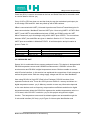
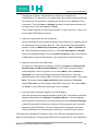
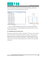
Figure 4-4 shows two PCBs which are designed during work on this project. Figure 43(a) is designed without power management unit. The schematic diagram of the wristbelt shows in Figure 4-4(b) which is inserted on the PCB boards in Figure 4.3(b). But it
designed on 48mm PCB board.
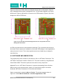
Figure 4-4: (a) PCB without Power Management Unit-37.4 mm (b) PCB with Power
Management Unit-48 mm.
In PCB all components are connected with electrically. The connections show lines on
the board. Every component is soldered on the board. PCB design is more applicable to
reduce the size of circuit. This is less expensive and more reliable way to design for
manufacturing.
4.2 SOFTWARE IMPLEMENTATION
The programming code is written for this device in C# on .NET Micro Framework. The
.NET Micro Framework is earlier in Section 2.5. The code is written by using Microsoft
Visual Studio 2008. This section points out the code for every component.
Meridian/P runs in .NET Micro Framework. It requires downloading Device Solution
SDK to work on this microcontroller. Version 3 is used for this project. As well as
download .NET Micro Framework 3.5 from Microsoft Website.
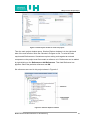
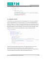
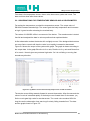
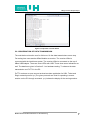
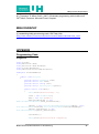
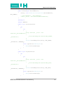
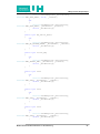
Open a new project by selecting New >> Project. The window appears shown in
Figure 4-5. Select Micro Framework >> Console application >> OK.
Md Ibna Zaman/ InterHome-Extension on Assisted Living
30
30
School of Engineering and Technology
BEng Final Year Project Report
Figure 4-5: New Project window for creat new porject
Then the main project window opens. Sloution Explore windows is in the right-hand
side of the main window. Wirte the C# code in Program.cs file. To write the code
requires add Refererences. Sometimes requires writing code against an external
component so the project must first contain a reference to it. References can be added
by right-clicking on the Reference>> Add References. Then Add Reference box
appears. Select the particular reference and OK.
Six references are used in this project shows in Figure 4-6.
Figure 4-6: Solution Explorer window.
Md Ibna Zaman/ InterHome-Extension on Assisted Living
31
31
School of Engineering and Technology
BEng Final Year Project Report
In the code references are added at the beginning then the code is written under public
class shows in Figure 4-7. To write reference, starts with using-statement.
Figure 4-7: Writing references in main programming code.
In this project temperature sensor and accelerometer is coded in RoomBoard.cs. I2CBus and serial port are coded separately. All the components are altogether coded in
Program.cs.
4.2.1 TEMPERATURE SENSOR AND ACCELEROMETER
In this project using DS1624 as temperature sensor and LIS302DL accelerometer. The
codes are for the sensors in RoomBoard.cs shows in Figure 4-8.
Figure 4-8: (a) Code for DS1624 (b) Code for LIS302DL
The code is under the class in different block such as Fields, Constants, Constructors
etc. To create the block writes down #region region_name. Every block differs in
function.
That is for I2C bus configuration. This provides option for time for I2C bus.
Md Ibna Zaman/ InterHome-Extension on Assisted Living
32
32
School of Engineering and Technology
BEng Final Year Project Report
It is for declaring the registers. The default address is associated on Slave
Address (SDA) for both sensors. The address is 8-bet length.
For DS1624 has seven bits of control byte. The control byte is defined with four bit
control code that is 1001 binary and this can operate Read and Write operations. [29] The
control byte comes after the START condition from the master device. Three bits are left
from control byte. The last three bits are called device select bits (A2, A1and A0). [29]
The last bits can perform “Read” and “Write” operation. When last bits are “1” then it
works as “Read” operation and “0” for “Write” operation. [29] Here the last bits set all “0”.
Default address for DS1624 is 01001000 in binary. So the number converts in
Hexadecimal. It is 48. The all register values for DS1624 insert in constant shows in
Figure 4-9(a).
Figure 4-9: (a) Register declaration of DS1624 (b) Register declaration of LIS302DL
Similar to the DS1624, the accelerometer defines the default address by SDA. In
LIS302DL the 6 bits after the START signal contains the slave address. When the SC is
HIGH then START operates at HIGH to LOW operation on the data line. [30]
Md Ibna Zaman/ InterHome-Extension on Assisted Living
33
33
School of Engineering and Technology
BEng Final Year Project Report
Master transmits this and makes the bus busy. The last bit (8th) depends on Master‟s
receiving or transmitting mode to the slave. [30] So first Bit is START and then next 6-bit
is Slave Address. In this accelerometer Slave Address is 001110 in binary. [30] The last
bit is LSB which can be modified by SDO pin. When SDO is connected with supply
voltage then LSB is „1‟. [30] On other hand if connects with ground (GND) then LSB „0‟. In
this design SDO is grounded so LSB is „0‟. [30]
So default address of LIS302DL is 00011100. [30] Now convert in hexadecimal that is
“1C”. All registers including default register mapping show in Figure 4-5(b). There all
values are inserted in constant.
It defines as class methods that executed when an object is created
[39] Here
the objects are defined in Constant block.
The constructor is called I2C bus time out, bus speed and default address for DS1624
and addressed clock rate and default address for LIS302DL.
It is located the resister mapping except default register. It defines the
register address operation mode. Both sensors are worked as a slave device. After
START the slave address is sent. I2C Slave Address can operate in Read/Write Mode.
In this block the operation mode is defined. If the register address is only Write-mode
then it works in set-statement. When the register address is only Read-mode then it
works in get-statement. In other hand when the register address is in Read/Write then it
uses both statements. The output can get from only Read type register.
Figure 4-10 shows the Member-Block only for the Start Conversion Temperature
register of DS1624. Here using only set-statement as the I2C Slave Address of Start
Conversion register is only in Write-mode.
Md Ibna Zaman/ InterHome-Extension on Assisted Living
34
34
School of Engineering and Technology
BEng Final Year Project Report
Figure 4-10: Code for inside the memory-block of DS1624
In LIS302DL, Ctrl_Reg3-register is mapped in Read/write mode and HP_Filter_Resetregister is only Read mode. Figure 4-11 shows that both statements are used for
Ctrl_Reg3 register and only get-statement is used for HP_Filter_Reset-register.
Figure 4-11: Code for inside the memory-block of LIS302DL
This requires for dispose any objects. It performs to release
any allocated resources. This method is not applied in this project.
DS1624 starts conversion at the register value of EE in hexadecimal. [29] The
measurement range for LIS302DL accelerometer is ±2g to ±8g. [30] But it depends on
the Full Scale (FS) selection, the default of FS is „0‟ for acceleration range of ±2g. [30] If
FS bit of the register sets to „1‟ then it measures acceleration at the range of ±8g. [30]
FS bit is used in CTRL_REG1. This is 8-bit register and the value is 20 in hexadecimal.
The bit outlines are described in Table 4.1.
Md Ibna Zaman/ InterHome-Extension on Assisted Living
35
35
School of Engineering and Technology
BEng Final Year Project Report
Table 4-1: Register CTRL_REG1 description [30]
The output data range of I2C bus picks 100Hz by selecting DR equals to „0‟. Here FS
sets to „1‟ as well as enable x, y and z axis. The power down control sets to „0‟. So the
value for Zen, Yen and Xen sets to „1‟. In this project self test mode is not used. So
STP and STM sets to „1‟. So set the value for CTRL_REG1 is 01100111 in binary. If
converts the value in hexadecimal is 67.
So writes the code for accelerometer and temperature sensor. The output data of
accelerometer is read by OUT_X, OUT_Y and OUT_Z register. The written code for
temperature sensor and accelerometer is shown in Figure 4-12.
Md Ibna Zaman/ InterHome-Extension on Assisted Living
36
School of Engineering and Technology
BEng Final Year Project Report
Figure 4-12: Measurement code for temperature sensor and accelerometer
4.2.2 PANIC BUTTON
The panic button is connected with a GPIO11 of Meridian/P. Define the panic button as
ipPanic by using interrupt port in main function. The port resistor mode is disabled and
indicated GPIO 11. If panic button is pressed then the system is interrupted by defining
time.
Figure 4-13 shows that GPIO pin is defined by using if-statement. By using
Thread.sleep method sets priority for interrupt and duration. Here sets 500ms for panic
button. By pressing button the system interrupts for 500ms and sends the data through
serial port to XBee. Here use debug.print so it prints the text by string and xbee.Write
Data method. So the receiver prints the same statement “Need Assistant”. The code
shows in Figure 4-13.
Md Ibna Zaman/ InterHome-Extension on Assisted Living
3737
School of Engineering and Technology
BEng Final Year Project Report
Figure 4-13: Programming code for Panic Button
4.2.3 EMBEDDED DEVICE
The concept of this project is based on an embedded device. This section introduces
how the code addressed all components together. The code for embedded device is
written in Program.cs. In Figure 4-14 shows that the components are defined under the
class library. Then each component is defined. Here XBee using COM1 serial port and
declares RoomBoard. It prints “initialising...” when the device starts debugging. When
initialising completes then a massage appears on screen “initialising complete”.
Figure 4-14: A part of code for embedded device in Progarm.cs
Figure 4-15 shows the output code is written. The output comes out in text. First it
shows the temperature, then the value of x-axis, y-axis and z-axis of the
accelerometer. It prints on during debugging as well as it shows in text on the receiver.
The received data from the device is shown and analysed Section 5.2.
Md Ibna Zaman/ InterHome-Extension on Assisted Living
38
38
School of Engineering and Technology
BEng Final Year Project Report
Figure 4-15: Code for output of the embedded device.
4.2.4 I2C-BUS OPERATION
DS1624 and LIS302DL are connected with Meridian/P through I2C two wires bus. This
bus is described in section 2.4. It has data transmission protocol. The device is worked
as “transmitter” when the device sends data to the bus. [29] It acts as “receiver” when
receives data from the bus. The device is called “master” when it controls the data, and
if the device is controlled by the master then called “slave”. [29] DS1624 and LIS302DL,
both are worked as slave device shows in Figure 4-16. [29] [30] Both sensors operate in
START and STOP condition. The “master” generates a clock signal is Serial Clock
(SCL). [29]
Figure 4-16: Code from I2C.cs
When the data and clock lines both are in HIGH then the bus is not in busy condition.
So that is time to transfer data. In I2C bus, data transfer starts when the bus is not
busy. [29][30]
If the data line changes from HIGH to LOW but the clock line remains HIGH. The
situation is called START condition. There one clock pulse per bit of data. [29]
After START condition the data is valid till the data line remains HIGH of the duration of
clock signal. [30] Unlimited data can be transferred after START condition till STOP, but
it is specified by the “master” device.
The bus can transfer data in two modes explained in Section 2.4. Those are called
regular mode (100Kbit/s) and fast mode (400kbit/s). [22] Here the sensors can run
transfer in both mode but selects regular mode (100Kbit/s) for both sensors.
Md Ibna Zaman/ InterHome-Extension on Assisted Living
39
39
School of Engineering and Technology
BEng Final Year Project Report
After receiving data, the receiving device generates an acknowledgement. It is
compulsory to transfer data with acknowledge. [30] During the acknowledge pulse the
transmitter release the data line. The data line stables LOW at the HIGH period of
acknowledgement related clock signal. [30]
When stops generating acknowledge bit on the last byte then the “master” sends
notification of the data ending. [30] The slave makes the data line form LOW to HIGH
and the “master” initialises STOP condition. [30]
4.2.5 SERIAL PORT
Here using standard serial port COM1 in .NET Micro Framework. XBee communicates
by using serial port.
Figure 4-17: Code written in main function declares XBee.
5 TESTING AND RESULT ANALYSIS
The proposed device is testing after designing the hardware and programming. This
chapter describes on the results which got from the hardware and software
implementations. In Section 5.1 focused on the hardware testing. This testing is
basically based on the breadboard design. But software testing is on the programming
code and analysed on the outputs that get from the designed device in Section 5.2.
5.1 HARDWARE
After designing the circuit on the breadboard measures the output voltage of different
points by using multi-meter. The whole device is powered by Meridian/P. Pin-3 of
Meridian/P is used here as source for 3.3V for the sensors. The system requires
approximately 305mA current that is measured by multi-meter. Some components are
connected with LED in the breadboard. Those LEDs give indication. Those LEDs can
be used for testing as well.
Md Ibna Zaman/ InterHome-Extension on Assisted Living
40
40
School of Engineering and Technology
BEng Final Year Project Report
Two LEDs are connected with XBee module. Pin-13 of XBee defines as Module Status
Indicator and Pin-15 is notified as associate indicator. [25] Pin-13 connects with red
colour LED and Pin-15 connects with green colour LED. When the system is running
then the Red-LED turns ON and Green-LED blinks continuously is shown in Figure 5-1
Three LEDs are used in Charging IC. Pin-8 is for power supply indication which is
connected with Red-LED. Pin-3 and Pin-4 are called STAT pin for charging IC. [35] The
details of connection are provided in Section 3.2.4. Green-LED connects with Pin-3 and
Yellow-LED connects with Pin-4. When the Li-Ion battery is on charged then the RedLED and Yellow-LED turn on. When it finishes charging then both LEDs are turned OFF.
Green-LED is for charging status indicator which is for interfacing by microcontroller.
Figure 5-1: Hardware Testing
A Yellow-LED connects with RECOM DC-DC converter. This converts 3.3V DC to 5V
DC. The Li-Ion battery is connected with Vin -pins (Pin-1 and Pin-2). These pins are
used for input supply. The LED is connected in series with Vout -pins (Pin-3 and Pin-4).
It turns ON when the system runs by the battery. That means the supply voltage has
converted.
After designing on breadboard, the transmission of the system can be checked by
using another XBee. This separate XBee is connected on the XBee USB Adaptor
shows in Figure 5.2. This is counted as receiver XBee.
Md Ibna Zaman/ InterHome-Extension on Assisted Living
41
School of Engineering and Technology
BEng Final Year Project Report
Figure 5-2: XBee USB Adaptor [40]
When the designed system turns OFF means no data transmission then LED-1(Blue)
and LED-5 (Green) turn OFF. LED-2 (Pink/Red) consists of two LEDs. LED-2 turns in
Red colour and it blinks. LED-3 (Yellow) and LED-4 (Green) turn ON.
If the designed device turns ON then the receiving XBee changes the colour of LEDs.
LED-1(Blue) turns ON and LED-2 turns ON in Pink colour with blinking that means the
receiving XBee has got network of another XBee. That shows in Figure 5-1. As well as
the transmission process is running. LED-3 (Yellow) and LED-4 (Green) keep ON.
LED-6 (RED) turns ON at the beginning.
The designed hardware device is working properly. The system is tested and analysed
in above.
5.2 SOFTWARE
The programming code is written in C# language on .NET Micro Framework. It is
written in Microsoft Visual Studio 2008.The written code is applied on the hardware
design through Meridian/P. So the designed device is connected with a PC. The code
is implemented on the device through that PC. The code has already discussed in
Section 4.2.
Md Ibna Zaman/ InterHome-Extension on Assisted Living
42
42
School of Engineering and Technology
BEng Final Year Project Report
The accelerometer measures the body movement form -8g to +8g. G-force or
Gravitational Force is described earlier in Section 3.2.2. It can be varied in different
axis. In this section the output of the device is analysed. The measurements of
LIS302DL and DS1624 describe in this section.
The accelerometer measures the movement according to x-axis, y-axis and z-axis. The
G-force can be found in three position of the body. Gx is the movement for front-toback, Gy is for side-to-side and Gz is for head-to toe. [34]
Figure 5-3: (a) Direction of G-force of body in vertically (b) Direction of G-force in transversely [34]
Figure 5-3 (a) shows that Gy varies side-to-side vertically. If the body moves towards
left hand side then Gy is positive. [34] That means Gy is increasing. If it moves right
hand side then Gy is negative. It means theat Gy is decreasing.
Figure 5-3 (b) shows that Gx changes front to back in transverse way of the body
movement. It increases if body moves forward. [34]
Gz is common in both Figures. It varies in the movement of head to toe. Gz changes
from high and low at the time of the body moving towards the space. [32]
So here the LIS302DL accelerometer gets data in Gx, Gy and Gz according to the
movement of body. By pressing F5 in Microsoft Visual Studio 2008 debugs the whole
programming code. The output box shows the output of the system. All data come out
together. Then the designed device moves in different directions.
Md Ibna Zaman/ InterHome-Extension on Assisted Living
43
43
School of Engineering and Technology
BEng Final Year Project Report
First data is for temperature sensor, then x-axis, then comes y-axis and z-axis. The
date and time show after those values.
5.2.1 OBSERVATIONS FOR TEMPERATURE SENSOR AND ACCELEROMETER
For testing the temperature, touched the temperature sensor. The output value of
DS1624 increases towards high. The sensor gets the body temperature and increases
to high. It goes low after releasing the touched body.
The values of LIS302DL differ in movement of the device. The accelerometer is tested
free-fall and analysed the data in various positions that explained below.
At first observation makes the device still or slightly moves. If the designed device does
not move fast or remain still then the value is not rapidly increased or decreased.
Figure 5-4 shows the output of the system with graph. The graph is drawn according to
the output data. In the graph Blue-line is for x-axis, Red-line is for y-axis and Green-line
is for z-axis. No axis gives any extreme high value. So it is not falling or moving fast
towards any direction.
Figure 5-4: (a) Data of normal movement (b) Graph of the normal movement
The device moves falling towards forward in second observation. After few seconds the
value of x-axis is increased rapidly. If the body moves forward then Gx increases. [35]
So the x-axis gets high value for accelerometer. The x-axis value remains HIGH for
long time as the observation time was long for slowly failing towards front. The data
and the graph shows in Figure 5-5.
Md Ibna Zaman/ InterHome-Extension on Assisted Living
44
44
School of Engineering and Technology
BEng Final Year Project Report
Figure 5-5: (a) Data of falling towards forward (b) Graph of the output
For third observation, the designed device moves towards left hand side in front
direction. So the output data of x-axis and y-axis increase at a time. Because the
device moves forward so x-axis remains HIGH. As well as the device moves toward left
hand side so y-axis increases. After few seconds x-axis, y-axis and z-axis all are
remain stable shows in Figure 5-6. That means no fast movement. So the device falls
towards left hand side in forward direction and there is no rapid movement after falling.
Figure 5-6: (a) Data of falling towards left-hand side in forward way (b) Graph of the output
The device is tested failing towards right in forward direction at the last observation of
accelerometer. Gy gets decreasing for right side movement of the body. [34] The value
of x-axis goes HIGH due to rapid moving towards forward. The y-axis values decrease
Md Ibna Zaman/ InterHome-Extension on Assisted Living
45
School of Engineering and Technology
BEng Final Year Project Report
as the device moves on right hand side. All are shown in Figure 5-7. Similar to the rest
2nd and 3rd observations, after few seconds the data remain stable. So there is no
extreme movement of the body after falling on the surface.
Figure 5-7: (a) Data of falling towards right-hand side in front way (b) Graph of the output.
From these observations, it is identified temperature, falling and movement of the user
of this proposed wrist-belt.
5.2.2 OBSERVATION OF PANIC BUTTON
Panic button is connected with a GPIO pin of Meridian/P. This button is used for asking
help. When the button is pressed then the system is interrupted. The system sends
data for this interruption. If the button is touched by no means the system will not be
interrupted. So it can not send data for asking help. For asking assistance, the button
needs to hold for few second. After pressing the button, it shows on the output window
in Figure 5-8.
Md Ibna Zaman/ InterHome-Extension on Assisted Living
46
46
School of Engineering and Technology
BEng Final Year Project Report
Figure 5-8: Operation of Panic Button
5.2.3 OBSERVATION OF DATA TRANSMISSION
The wrist-belt monitors the user for 24 hours. So the data transmissions never stop.
For testing here uses another XBee Module as receiver. The receiver XBee is
connected with the InterHome system. The receiver XBee is connected on the top of
XBee USB Adapter. There are some LEDs with USB. Those show some indications as
well. The details are given in Section 5.1 on hardware testing. To observe the data
transmission use PuTTY in the PC.
PuTTY works as an open source terminal emulator application for SSH, Telnet and
Rlogin network protocol. [41] The given protocols are used for operating a remote
session on the PC through a network. [41] It shows the display of the running session.
Md Ibna Zaman/ InterHome-Extension on Assisted Living
47
0
BEng Final Year Project Report
School of Engineering and Technology
Figure 5-9: PuTTy window
PuTTy runs in all operating system. The PuTTY comes out with the window shows in
Figure 5-9. Serial port is used as connection mode for this project. When the receiving
XBee connects with USB adaptor then after installation it informs about the connected
serial line. “COM4” is used as serial line with interface speed of 9600 bps. All are
selected in Figure 5-9.
PuTTy runs after selecting Open. Two XBees are connected in a network. The
designed wrist-belt sends data and the receiving XBee is picked those data. The data
is sending through wireless network continuously. The device sends the data of
temperature sensor and accelerometer shows in Figure 5-10. In case of emergency, if
the users press panic button for asking help. It shows on the PuTTY display window by
writing “Need Assistance”. It is marked by blue underline in Figure 5-10.
Md Ibna Zaman/ InterHome-Extension on Assisted Living
48
School of Engineering and Technology
BEng Final Year Project Report
Figure 5-10: Data transmission in running session of PuTTY by using COM4
The display window of PuTTY is normally in black colour. But Figure 5-10 is inverted
for clear observation.
CH-6 PROJECT MANAGEMENT
Proper project management requires to progress for a project. This chapter focused on
project time management, resource analysis and risk assessment. At first made an
effective project plan. Literature search was done at the beginning of the project. Then
researched on the require components. After that a paper based design was made.
The design implemented on the breadboard. So the hardware design can be modified.
Some modifications have done. The programming code applied on hardware design
after working on the programming. Then whole designed device was tested.
6.1 TIME MANAGEMENT
Time management is essential in project. The Project plan is made on the
consideration of components ordering. Testing is very time consuming part of the
project. In every step of progress is checked. So the project is tested at the time of
designing and implementation. Sometime many components require extra time to
receive. In that time the project is progressed by developing another area. Some
allocated tasks are worked at a time. The proposed project plan is shown in Figure 6.1
with the based on working days.
Md Ibna Zaman/ InterHome-Extension on Assisted Living
49
49
School of Engineering and Technology
BEng Final Year Project Report
Figure 6-1: Summery of proposed the project plan
6.2 RESOURCE ANALYSIS
This embedded device is designed on then Meridian/P microcontroller. All components
are visible in market. Some components require separate adaptor to connect on the
breadboard. Here XBee and Charging IC need adaptor to connect on the breadboard.
That‟s why the additional cost in hardware has been increased.
In the software design, Microsoft Visual studio 2008 Professional is provided and
PuTTY is downloaded free from online. There is no cost in software development.
6.3 RISK ASSESMENT
This embedded device is wearable so it is designed to consider the human body. So
the risks of any danger are considered. This device is powered by Li-Ion battery. The
microcontroller requires 5V DC and 80mA current. [28] The whole device need
approximate 300mA of current. It operates at very low voltage and current. So there is
no risk of electric shock. The proposal PCB is designed on 48mm. So the final product
would be very light weight to bind on wrist.
Md Ibna Zaman/ InterHome-Extension on Assisted Living
50
50
School of Engineering and Technology
BEng Final Year Project Report
7CONCLUSION
The aim of this project is to design a device for assistive residence which will send data
wirelessly to the existing Smart Home system called InterHome. By sending data, the
embedded device monitors and updates the health condition of the assistive residence.
So a wrist-belt is proposed which is for 24 hours home-based health monitoring
system.
The device is designed with the Meridian/P, body sensors and XBee. By using XBee,
the device transmits data to the receiver is shown in Section 5.2.3. So the main aim of
this project has successfully achieved.
Additionally Power Management Unit is added for charging the battery. This unit is
working properly. So the device can work as wireless and portable device.
So the wrist-belt is low-cost and remote monitoring system which has been developed.
It enables to provide an assistive person to retain independent lifestyle while he or she
still is being monitored. It provides long-term data and continuous monitoring. The
device provides more security as well. The designed system has the potential to
reduce additional health care service costs by facilitating more efficient use of health
care technology. So the commercial aspects and future recommendation are included
in this chapter in Section 7.1 and Section 7.2.
7.1 COMMERCIAL AND SOCIAL ASPECTS
This project has many commercial and social aspects. A large amount of world
population will be grown older near future. According to Technology Strategy Board
UK,more than a third of the world population will be over 65 by 2050. [42]
Different surveys have done to alarm about the increase rate ageing people. The
European Commission has predicted that the UK will see about 44% increases in the
60 and over age range between 1995 and 2025. [9] According to Office for National
Statistics UK, there were 1.3 million people aged 85 and over in the UK in 2007 that is
predicted to be 3.1 million by 2032. [43]
So it will be hard to assure good health service with the growth rate of elder people.
Nowadays modern technology is utilised in health sector to provide better service in
Md Ibna Zaman/ InterHome-Extension on Assisted Living
51
51
School of Engineering and Technology
BEng Final Year Project Report
home. This project is for providing health monitoring service from home. This device is
designed with concept of 24/7 health monitoring for assistive residences. This wrist-belt
can be used by old and disable person. By using this, the person gets care in home
environment. It provides more independence and flexibility as well.
There are many patients who are suffering from long-term health condition. They are
hospitalised due to 24 hours monitoring. But they can be monitored by using assistive
technology. Approximately 30% of assisted living residences suffer from long-term
health condition and 72% are inpatient bed days. [44]
This technology is also applicable for the patients who stay in bed for long time. So the
doctor can checked update health data of the patient with the help of technology. The
assistive technology helps to provide more home based care. So it helps to reduce the
cost.
This project has carries a vital role for community. Many old people are lived alone in
their home. Their health can be motored continuously by using this assistive
technology. According to Age Concern organisation, 11% of aged 65 or over are live
always lonely and aged 75 and over living alone will increase by over 40% in UK next
20 years. [45]
This device is also suitable for care home service provider. They can monitor multiple
patients by using this technology at the same time. In care home many patients suffer
from different motor neuron diseases. So they are immobile and some have problem in
speech. Their movement can be monitored by using this device. This is wireless device
so they feel more independence and secure.
The market ability of health monitored technology is very high. According to The
Wireless Association CITA, the current market for home-based, wireless health care
product in USA is $304 million and the market is expected to grow to $4 billion next 3
years. [46]
The future market of this type of product is wide. Different companies and organisations
are still working to develop in various products related this area. The home-based health
monitor technology type product of would be used widespread near future.
Md Ibna Zaman/ InterHome-Extension on Assisted Living
52
School of Engineering and Technology
BEng Final Year Project Report
7.2 FUTURE DEVELOPMENT
Here proposed a wrist-belt which monitors only movement and temperature. The
designed device has successfully sends data to the receiver. In the market only one
product can do only single task. But here this single device is doing multi-tasks. The
device is using I2C bus which is multi-master bus. In future more sensors can be
added with this I2C bus. Such as blood pressure sensor, pulse-oximeter or heart-beat
monitor sensor etc. By doing this, one device can measure different health related data
at the same time.
This device can be used in care home service in future. So the same device will be
used among many users. The device transmits data through XBee network. So the
next step would be worked for multi users. If the device is used in care home basis,
then multiple patients send data by using the same network. The challenging part
would be identifying the patient through data. So every patient will be carried different
identification. All patients data will be come together but the data can be distinguished
by using patients ID. So by upgrading this system in future, the care service provider
will be able to monitor a number of patients. This application will be help to identify
patient‟s data in emergency situtation.
More works can be done in LIS302DL accelerometer. Only CTRL_REG1 register is
used in this project. To get more accurate value of movement, it is requires to work on
other registers of LIS302DL. So working on the other registers is helpful for better
measurement.
The Charging IC MCP73837 is interface able with the Meridian/P. The charging system
can be controlled by interfacing with Meridian /P. The IC has auto shut down mode and
low voltage indication system. Both systems would be worked if the IC is interfaced
with Meridian/P. So here proposed to connect the charging IC with GPIO pin of
Meridian/P and worked on programming with this.
It has already tested that the device works wirelessly. Now the device is transmitting
data with XBee. In future the data transmitting range can be high by using XBee-Pro.
Md Ibna Zaman/ InterHome-Extension on Assisted Living
53
School of Engineering and Technology
BEng Final Year Project Report
REFERENCES
[1] Joseph,Harold. Swafford, Bob & Terry, Stephen. (April 1997). MEMS in the Medical
World. Retrieved October 25, 2009, from
http://archives.sensorsmag.com/articles/0497/medical/main.shtml
[2] Jones, P. M. (2009, January 19). Assisted Living - A Brief History and Definition.
Retrieved March 23, 2010, from http://ezinearticles.com/?Assisted-Living---A-Brief-History-and-Definition&id=1898892
[3] CodeBlue: Wireless Sensors for Medical Care. Retrieved March 23, 2010 from
http://fiji.eecs.harvard.edu/CodeBlue
[4] Mercury: A Wearable Sensor Network Platform for High-Fidelity Motion Analysis.
Retrieved March 23, 2010 http://fiji.eecs.harvard.edu/Mercury
[5]Ross, P.E. (December 2008). Managing Care Through the Air. Retrieved April 1,
2010, from
http://www.cs.indiana.edu/surg/pervasive/class_materials/ManagingCareThroughtheAir
.pdf
[6]Ubiquitous Monitoring Environment for Wearable and Implantable Sensors,
Retrieved April 1, 2010, from http://www.doc.ic.ac.uk/vip/ubimon/home/index.html
[7] Telemedicine Archive. Retrieved March 24, 2010, from
http://www.medgadget.com/archives/telemedicine/
[8] Piix Wireless Home Cardiac Monitoring to Undergo Randomized Trial. (2009, June
25). Retrieved March 20, 2010 from
http://medgadget.com/archives/2009/06/wireless_home_cardiac_monitoring_to_underg
o_randomized_trials.html
[9] Porteus, J. & Brownsell, S. (2000). Exploring Technologies for Independent Living
for Older People. Retrieved April 3, 2010, from
http://www.housingcare.org/downloads/kbase/2334.pdf
[10] Innovative GPRS/UMTS mobile services for applications in healthcare. Retrieved
April 2, 2010 form http://www.mobihealth.org
Md Ibna Zaman/ InterHome-Extension on Assisted Living
54
54
School of Engineering and Technology
BEng Final Year Project Report
[11] Asada, Harry. (2009, April 8), Wearable blood pressure sensor offers 24/7
continuous. monitoring. Retrieved December 16, 2009, from
http://web.mit.edu/newsoffice/2009/techtalk53-21.pdf
[12] Oliver, N. & Fernando, Flores-Mangas. HealthGear: A Real-time Wearable
System for
Monitoring and Analyzing Physiological Signals. Retrieved April 5, 2010, from
ftp://ftp.research.microsoft.com/pub/tr/TR-2005-182.pdf
[13] Home Automation. Retrieved April 5, 2010, from http://home-automation.org/
[14] Home Automation, In Wikipedia. Retrieved March 28, 2010, from
http://en.wikipedia.org/wiki/Home_automation#Architecture//
[15] Home Automation. Retrieved April 6, 2010, from http://www.eslusa.com/home_automation.html
[16]Figure 2-1 Smart Home. Retrieved April 6, 2010, from
http://www.ciseco.co.uk/images/house.jpg
[17]Gross, Mark D. Smart House and Home Automation Technologies. Retrieved April
9, 2010, from http://depts.washington.edu/dmgftp/publications/pdfs/smarthouse98mdg.pdf
[18]King, N. (September 2003). SMART HOME-A DEFINATION. Retrieved April9,
2010, from http://www.housingcare.org/downloads/kbase/2545.pdf
[19] Craven,J. What Is a “Smart House”?. Retrieved April 9, 2010, from
http://architecture.about.com/od/buildyourhous1/g/smarthouse.htm
[20] Siau, J. Chen, C. Percival, E. InterHome. Retrieved April 10, 2010, from
http://interhome.herts.ac.uk/
[21] I2C Bus. Retrieved April10, 2010, from http://www.i2c-bus.org/
[22] The I2C-Bus and how to use it (including specification). Retrieved March 30, 2010,
from
http://www.datsi.fi.upm.es/docencia/Micro_C/i2c.pdf
[23] UM1024 I2C-bus specification and user manual. Retrieved April 10, 2010, from
http://www.nxp.com/documents/user_manual/UM10204.pdf
Md Ibna Zaman/ InterHome-Extension on Assisted Living
55
55
School of Engineering and Technology
BEng Final Year Project Report
[24] History of I2C interface. Retrieved April 11, 2010, from
http://www.lammertbies.nl/comm/info/I2C-bus.html
[25] XBee™/XBee-PRO™ OEM RF Modules Product Manual v1.06. Retrieved October
30, 2009 http://www.rev-ed.co.uk/docs/xbe001.pdf
[26] IEEE 802.15.4-2006. In Wikipedia. Retrieved April 4, 2010, from
http://en.wikipedia.org/wiki/IEEE_802.15.4-2003
[27] Sklar, B., (2001), Digital Communications: Fundamentals and Applications,
Prentice Hall, 2nd Edition: Sections 12.1 – 12.4
[28] Meridian/P Technical Reference Manual. Retrieved March 30, 2010, from
http://devicesolutions.net/Portals/0/Download/Documents/MeridianP%20Technical%20Reference%20Manual.pdf
[29] DS1624 Digital Thermometer and Memory Product Manual. Retrieved February18,
2010, from http://datasheets.maxim-ic.com/en/ds/DS1624.pdf
[30] LIS302DL MEMS Motion Sensor Product Manual. Retrieved April 4, 2010, from
http://www.st.com/stonline/books/pdf/docs/12726.pdf
[31] Serial Peripheral Interface (SPIV3) Block Description. Retrieved April 12, 2010,
from http://www.freescale.com/files/microcontrollers/doc/ref_manual/S12SPIV3.pdf
[32] Sircar, Sabyasachi., 2008. Principle of Medical Physiology (e-book), Thieme New
York, USA. Available At:
http://books.google.co.uk/books?id=zFl7y5xqHj4C&lpg=PA6&ots=wvifbtq21&dq=%22apparent%20acceleration%22%20%22gforce%22&pg=PA6#v=onepage&q=%22apparent%20acceleration%22%20%22gforce%22&f=true (Accessed- 2 March 2010).
[33] G Force. Retrieved April 10, 2010, from
http://newton.dep.anl.gov/askasci/phy99/phy99491.htm
[34]Voshell, M. (2004, November 28). High Acceleration and the Human Body.
Retrieved April 12, 2010, from http://csel.eng.ohio-state.edu/voshell/gforce.pdf
[35] MCP73837/8 Product manual. Retrieved March 15, 2010 from
http://ww1.microchip.com/downloads/en/DeviceDoc/22071a.pdf
Md Ibna Zaman/ InterHome-Extension on Assisted Living
56
56
School of Engineering and Technology
BEng Final Year Project Report
[36] RECOM DC-DC Convertor Product Manual. Retrieved Match 16, 2010, from
http://docseurope.origin.electrocomponents.com/webdocs/0d62/0900766b80d62039.pdf
[37] Breadboard. Retrieved April 10, 2010, from
http://www.kpsec.freeuk.com/breadb.htm
[38] Manufacturer of Printed Circuit Boards (PCB). Retrieved April 12, 2010, from
http://www.eiconnect.com/eiPcbRes.aspx?type=history
[39] Using Constructors (C# Programming Guide). Retrieved April10, 2010, from
http://msdn.microsoft.com/en-us/library/ms173115(VS.80).aspx
[40] Picture of XBee USB Adaptor. Retrieved April 12, 2010, from http://www.activerobots.com/products/parallax/xbee-usb-adapter.shtml
[41] PuTTY FAQ. Retrieved April 12, 2010, from
http://www.chiark.greenend.org.uk/~sgtatham/putty/faq.html
[42] ICT industries - rising to the assisted living challenge. Retrieved January 25, 2010,
from http://www.innovateuk.org/content/iain-gray/ict-industries-rising-to-the-assistedliving-chall.ashx
[43]Dunnell, K. (2008). Ageing and Mortality in the UK: National Statistician’s annual
article on the population. Retrieved April 8, 2010, from
http://www.statistics.gov.uk/articles/population_trends/DunnellMortalityAndAgeingPT13
4.pdf
[44] Assisted Living Innovation Platform. Retrieved April 9, 2010, from
http://www.innovateuk.org/_assets/pdf/assistedlivingip.pdf
[45] Harrop, A. Jopling, K. One Voice: Shaping our ageing society. Retrieved April 8,
2010, from http://press.helptheaged.org.uk/NR/rdonlyres/CD558156-BE2D-440BBA58-A16D393E6B35/0/OneVoiceReport.pdf
[46] Donal, B. (2009, December 10). CTIA: Wireless health currently a $304M market.
Retrieved April 11, 2010 from http://mobihealthnews.com/5722/ctia-wireless-healthcurrently-a-304m-market/
Md Ibna Zaman/ InterHome-Extension on Assisted Living
57
School of Engineering and Technology
BEng Final Year Project Report
[47] Thompson, D. Miles, Rob.S. (2007). Embedded programming with the Microsoft
.NET Micro Framewor. Microsoft Press. Chapter1.
BIBLIOGRAPHY
[1] Assisted-living facility gets technology assist, USA Today, Web:
http://www.usatoday.com/tech/news/techinnovations/2006-07-05-elder-tech_x.htm
APPENDIX
Programming Code
Program.cs
using
using
using
using
using
System;
Microsoft.SPOT;
Microsoft.SPOT.Hardware;
System.Threading;
DeviceSolutions.SPOT.Hardware;
namespace InterHomeMeriP
{
public class Program
{
private static RoomBoard room1;
private static XBee xbee;
private static string text;
private static InterruptPort ipPanic;
public static void Main()
{
Debug.Print("Initialising...");
room1 = new RoomBoard(0);
xbee = new XBee("COM1");
xbee.DataReceived += new
XBee.DataReceivedHandler(xbee_DataReceived);
ipPanic = new InterruptPort(MeridianP.Pins.GPIO11, true,
Port.ResistorMode.Disabled, Port.InterruptMode.InterruptEdgeHigh);
ipPanic.OnInterrupt += new
NativeEventHandler(ipPanic_OnInterrupt);
StartTimer();
Debug.Print("Initialisation complete");
Md Ibna Zaman/ InterHome-Extension on Assisted Living
58
School of Engineering and Technology
BEng Final Year Project Report
}
static void ipPanic_OnInterrupt(uint data1, uint data2,
TimeSpan time)
{
bool GPIO_Pin11 = true;
//
//
while (false)
{
if (ipPanic.Read() == true)
{
GPIO_Pin11 = !GPIO_Pin11;
Thread.Sleep(500); //Thrad used for time. So it
will stop for 500ms.
Debug.Print(DateTime.Now.ToString() + "|" +
ipPanic.Read().ToString());
text += DateTime.Now.ToString();
Debug.Print("Need Assistance");
xbee.WriteData("Need Assistance");
}
//
}
}
static void xbee_DataReceived(object sender,
XBeeDataReceivedEventArgs e)
{
Debug.Print("Received something");
}
private static void UpdateTick()
{
Thread.Sleep(200);
text = room1.Temperature.ToString() + "|" +
room1.GetAccelerometerValue()[0].ToString() + "|"
+ room1.GetAccelerometerValue()[1].ToString() + "|" +
room1.GetAccelerometerValue()[2].ToString() + "|";
text += DateTime.Now.ToString();
Debug.Print(text);
xbee.WriteData(text);
}
#region Main thread
// Delegate type for the callback
private delegate void VoidProcDelegate();
private static Thread TimerThread;
/// <summary>Starts the timer thread for the
animation</summary>
static void StartTimer()
{
TimerThread = new Thread(new
ThreadStart(TimerThreadProc));
TimerThread.Start();
}
Md Ibna Zaman/ InterHome-Extension on Assisted Living
59
School of Engineering and Technology
BEng Final Year Project Report
static void TimerThreadProc()
{
while (TimerThread.ThreadState == ThreadState.Running)
{
DispatcherOperation op =
Dispatcher.CurrentDispatcher.BeginInvoke(new
VoidProcDelegate(UpdateTick));
op.Wait();
Thread.Sleep(100);
}
}
#endregion
}
}
Md Ibna Zaman/ InterHome-Extension on Assisted Living
60
School of Engineering and Technology
BEng Final Year Project Report
RoomBoard.cs
using System;
using System.IO;
using Microsoft.SPOT;
using Microsoft.SPOT.Hardware;
using System.Threading;
namespace InterHomeMeriP
{
public class RoomBoard
{
#region Drivers for on-board devices
internal sealed class DS1624
{
#region Fields
private I2CDevice.Configuration config;
//private I2CSlave _slave;
//private byte _deviceAddress;
private byte[] _dataBuffer = new byte[2] { 0x00, 0x00 };
#endregion
#region Constants
const
const
const
const
const
const
const
const
const
int TIMEOUT = InterHomeConfig.I2C_TIMEOUT;
int BUS_SPEED = InterHomeConfig.I2C_BUS_SPEED;
byte DEFAULT_Address = 0x48;
byte REG_IO = 0x00;
byte REG_MEMORY = 0x17;
byte REG_CONFIG = 0xAC;
byte REG_TEMP = 0xAA;
byte REG_START = 0xEE;
byte REG_STOP = 0x22;
#endregion
#region Constructors
/// <summary>
/// DS1624 default address
/// </summary>
public DS1624()
: this(DS1624.DEFAULT_Address)
{
}
public DS1624(int deviceAddress)
{
config = new
I2CDevice.Configuration((byte)(DEFAULT_Address + deviceAddress),
BUS_SPEED);
}
/// <summary>
/// DS1624 Temperature Monitoring
/// </summary>
Md Ibna Zaman/ InterHome-Extension on Assisted Living
61
School of Engineering and Technology
BEng Final Year Project Report
/// <param name="deviceAddress"></param>
public DS1624(byte deviceAddress)
{
config = new I2CDevice.Configuration(deviceAddress,
BUS_SPEED);
//_deviceAddress = deviceAddress;
//this._slave = new I2CSlave(deviceAddress);
}
#endregion
#region Members
public byte StartConversion
{
set
{
try
{
/*
using (I2CSlave _slave = new
I2CSlave(_deviceAddress))
{
_slave.WriteRegister(DS1624.REG_START,
_dataBuffer);
}
*/
I2CSlave.WriteRegister(config, REG_START,
_dataBuffer, TIMEOUT);
}
catch (System.IO.IOException e)
{
Debug.Print(e.Message);
}
}
}
public byte StopConversion
{
set
{
try
{
/*
using (I2CSlave _slave = new
I2CSlave(_deviceAddress))
{
_slave.WriteRegister(DS1624.REG_STOP,
_dataBuffer);
}
*/
I2CSlave.WriteRegister(config, REG_STOP,
_dataBuffer, TIMEOUT);
}
catch (System.IO.IOException e)
{
Debug.Print(e.Message);
}
}
Md Ibna Zaman/ InterHome-Extension on Assisted Living
62
School of Engineering and Technology
BEng Final Year Project Report
}
/// <summary>
/// Temperature Reading
/// </summary>
public byte Temp
{
get
{
try
{
/*
using (I2CSlave _slave = new
I2CSlave(_deviceAddress))
{
_slave.ReadRegister(DS1624.REG_TEMP,
_dataBuffer);
}
*/
I2CSlave.ReadRegister(config, REG_TEMP,
_dataBuffer, TIMEOUT);
}
catch (System.IO.IOException e)
{
Debug.Print(e.Message);
}
return _dataBuffer[0];
}
}
/// <summary>
/// Memory
/// </summary>
public byte Memory
{
get
{
try
{
/*
using (I2CSlave _slave = new
I2CSlave(_deviceAddress))
{
_slave.ReadRegister(DS1624.REG_MEMORY,
_dataBuffer);
}
*/
I2CSlave.ReadRegister(config, REG_MEMORY,
_dataBuffer, TIMEOUT);
}
catch (System.IO.IOException e)
{
Debug.Print(e.Message);
}
return _dataBuffer[0];
}
}
#endregion
/// <summary>
Md Ibna Zaman/ InterHome-Extension on Assisted Living
63
School of Engineering and Technology
BEng Final Year Project Report
/// Config
/// </summary>
public byte Config
{
get
{
try
{
/*
using (I2CSlave _slave = new
I2CSlave(_deviceAddress))
{
_slave.ReadRegister(DS1624.REG_CONFIG,
_dataBuffer);
}
*/
I2CSlave.ReadRegister(config, REG_CONFIG,
_dataBuffer, TIMEOUT);
}
catch (System.IO.IOException e)
{
Debug.Print(e.Message);
}
return _dataBuffer[0];
}
}
#region IDisposable Members
/// <summary>
/// Dispose object
/// </summary>
public void Dispose()
{
/*
using (I2CSlave _slave = new I2CSlave(_deviceAddress))
{
_slave.Dispose();
}
*/
}
#endregion
}
#endregion
internal sealed class LIS302DL
{
#region Fields
private I2CDevice.Configuration _deviceConfig;
private int _timeOut = 50;
private byte[] _dataBuffer = new byte[2] { 0x00, 0x00 };
#endregion
Md Ibna Zaman/ InterHome-Extension on Assisted Living
64
School of Engineering and Technology
BEng Final Year Project Report
#region Constants
const
const
const
const
const
const
const
const
const
const
const
const
const
const
const
const
const
const
const
const
const
const
const
const
const
const
int CLOCK_Rate = 100;
byte DEFAULT_Address = 0x1C;
byte REG_WHO_AM_I = 0x0F;
byte REG_CTRL_REG1 = 0x20;
byte REG_CTRL_REG2 = 0x21;
byte REG_CTRL_REG3 = 0x22;
byte REG_HP_FILTER_RESET = 0x23;
byte REG_STATUS_REG = 0x27;
byte REG_OUTX = 0x29;
byte REG_OUTY = 0x2B;
byte REG_OUTZ = 0x2D;
byte REG_FF_WU_CFG_1 = 0x30;
byte REG_FF_WU_SRC_1 = 0x31;
byte REG_FF_WU_THS_1 = 0x32;
byte REG_FF_WU_DURATION_1 = 0x33;
byte REG_FF_WU_CFG_2 = 0x34;
byte REG_FF_WU_SRC_2 = 0x35;
byte REG_FF_WU_THS_2 = 0x36;
byte REG_FF_WU_DURATION_2 = 0x37;
byte REG_CLICK_CFG = 0x38;
byte REG_CLICK_SRC = 0x39;
byte REG_CLICK_THSY_X = 0x3B;
byte REG_CLICK_THSZ = 0x3C;
byte REG_CLICK_TimeLimit = 0x3D;
byte REG_CLICK_Latency = 0x3E;
byte REG_CLICK_Window = 0x3F;
#endregion
#region Constructors
/// <summary>
/// LIS302DL default address 0x1c
/// </summary>
public LIS302DL()
: this(LIS302DL.DEFAULT_Address)
{
}
/// <summary>
/// LIS302DL Triple Axis Accelerometer
/// </summary>
/// <param name="deviceAddress"></param>
public LIS302DL(byte deviceAddress)
: this(deviceAddress, CLOCK_Rate)
{
}
/// <summary>
/// LIS302DL Triple Axis Accelerometer
/// </summary>
/// <param name="deviceAddress"></param>
/// <param name="clockRate"></param>
public LIS302DL(byte deviceAddress, int clockRate)
{
Md Ibna Zaman/ InterHome-Extension on Assisted Living
65
School of Engineering and Technology
BEng Final Year Project Report
_deviceConfig = new I2CDevice.Configuration(deviceAddress,
clockRate);
}
#endregion
#region Members
/// <summary>
/// Device identification register. This register contains the
device identifier for LIS302DL (set to 3Bh)
/// </summary>
public byte Who_Am_I
{
get
{
I2CSlave.ReadRegister(_deviceConfig,
LIS302DL.REG_WHO_AM_I, _dataBuffer, _timeOut);
return _dataBuffer[0];
}
}
public byte Ctrl_Reg1
{
set
{
I2CSlave.WriteRegister(_deviceConfig,
LIS302DL.REG_CTRL_REG1, value, _timeOut);
}
get
{
I2CSlave.ReadRegister(_deviceConfig,
LIS302DL.REG_CTRL_REG1, _dataBuffer, _timeOut);
return _dataBuffer[0];
}
}
public byte Ctrl_Reg2
{
set
{
I2CSlave.WriteRegister(_deviceConfig,
LIS302DL.REG_CTRL_REG2, value, _timeOut);
}
get
{
I2CSlave.ReadRegister(_deviceConfig,
LIS302DL.REG_CTRL_REG2, _dataBuffer, _timeOut);
return _dataBuffer[0];
}
}
public byte Ctrl_Reg3
{
set
{
Md Ibna Zaman/ InterHome-Extension on Assisted Living
66
School of Engineering and Technology
BEng Final Year Project Report
I2CSlave.WriteRegister(_deviceConfig,
LIS302DL.REG_CTRL_REG3, value, _timeOut);
}
get
{
I2CSlave.ReadRegister(_deviceConfig,
LIS302DL.REG_CTRL_REG3, _dataBuffer, _timeOut);
return _dataBuffer[0];
}
}
public byte HP_Filter_Reset
{
get
{
I2CSlave.ReadRegister(_deviceConfig,
LIS302DL.REG_HP_FILTER_RESET, _dataBuffer, _timeOut);
return _dataBuffer[0];
}
}
public byte Status_Reg
{
get
{
I2CSlave.ReadRegister(_deviceConfig,
LIS302DL.REG_STATUS_REG, _dataBuffer, _timeOut);
return _dataBuffer[0];
}
}
public byte OutX
{
get
{
I2CSlave.ReadRegister(_deviceConfig,
LIS302DL.REG_OUTX, _dataBuffer, _timeOut);
return _dataBuffer[0];
}
}
public byte OutY
{
get
{
I2CSlave.ReadRegister(_deviceConfig,
LIS302DL.REG_OUTY, _dataBuffer, _timeOut);
return _dataBuffer[0];
}
}
public byte OutZ
{
get
{
I2CSlave.ReadRegister(_deviceConfig,
LIS302DL.REG_OUTZ, _dataBuffer, _timeOut);
return _dataBuffer[0];
}
Md Ibna Zaman/ InterHome-Extension on Assisted Living
67
School of Engineering and Technology
BEng Final Year Project Report
}
public byte FF_WU_CFG_1
{
set
{
I2CSlave.WriteRegister(_deviceConfig,
LIS302DL.REG_FF_WU_CFG_1, value, _timeOut);
}
get
{
I2CSlave.ReadRegister(_deviceConfig,
LIS302DL.REG_FF_WU_CFG_1, _dataBuffer, _timeOut);
return _dataBuffer[0];
}
}
public byte FF_WU_CFG_2
{
set
{
I2CSlave.WriteRegister(_deviceConfig,
LIS302DL.REG_FF_WU_CFG_2, value, _timeOut);
}
get
{
I2CSlave.ReadRegister(_deviceConfig,
LIS302DL.REG_FF_WU_CFG_2, _dataBuffer, _timeOut);
return _dataBuffer[0];
}
}
public byte FF_WU_SRC_1
{
get
{
I2CSlave.ReadRegister(_deviceConfig,
LIS302DL.REG_FF_WU_SRC_1, _dataBuffer, _timeOut);
return _dataBuffer[0];
}
}
public byte FF_WU_SRC_2
{
get
{
I2CSlave.ReadRegister(_deviceConfig,
LIS302DL.REG_FF_WU_SRC_2, _dataBuffer, _timeOut);
return _dataBuffer[0];
}
}
public byte FF_WU_THS_1
{
set
{
I2CSlave.WriteRegister(_deviceConfig,
LIS302DL.REG_FF_WU_THS_1, value, _timeOut);
}
Md Ibna Zaman/ InterHome-Extension on Assisted Living
68
School of Engineering and Technology
BEng Final Year Project Report
get
{
I2CSlave.ReadRegister(_deviceConfig,
LIS302DL.REG_FF_WU_THS_1, _dataBuffer, _timeOut);
return _dataBuffer[0];
}
}
public byte FF_WU_THS_2
{
set
{
I2CSlave.WriteRegister(_deviceConfig,
LIS302DL.REG_FF_WU_THS_2, value, _timeOut);
}
get
{
I2CSlave.ReadRegister(_deviceConfig,
LIS302DL.REG_FF_WU_THS_2, _dataBuffer, _timeOut);
return _dataBuffer[0];
}
}
public byte FF_WU_DURATION_1
{
set
{
I2CSlave.WriteRegister(_deviceConfig,
LIS302DL.REG_FF_WU_DURATION_1, value, _timeOut);
}
get
{
I2CSlave.ReadRegister(_deviceConfig,
LIS302DL.REG_FF_WU_DURATION_1, _dataBuffer, _timeOut);
return _dataBuffer[0];
}
}
public byte FF_WU_DURATION_2
{
set
{
I2CSlave.WriteRegister(_deviceConfig,
LIS302DL.REG_FF_WU_DURATION_2, value, _timeOut);
}
get
{
I2CSlave.ReadRegister(_deviceConfig,
LIS302DL.REG_FF_WU_DURATION_2, _dataBuffer, _timeOut);
return _dataBuffer[0];
}
}
public byte CLICK_CFG
{
set
{
I2CSlave.WriteRegister(_deviceConfig,
LIS302DL.REG_CLICK_CFG, value, _timeOut);
Md Ibna Zaman/ InterHome-Extension on Assisted Living
69
School of Engineering and Technology
BEng Final Year Project Report
}
get
{
I2CSlave.ReadRegister(_deviceConfig,
LIS302DL.REG_CLICK_CFG, _dataBuffer, _timeOut);
return _dataBuffer[0];
}
}
public byte CLICK_SRC
{
get
{
I2CSlave.ReadRegister(_deviceConfig,
LIS302DL.REG_CLICK_SRC, _dataBuffer, _timeOut);
return _dataBuffer[0];
}
}
public byte CLICK_THSY_X
{
set
{
I2CSlave.WriteRegister(_deviceConfig,
LIS302DL.REG_CLICK_THSY_X, value, _timeOut);
}
get
{
I2CSlave.ReadRegister(_deviceConfig,
LIS302DL.REG_CLICK_THSY_X, _dataBuffer, _timeOut);
return _dataBuffer[0];
}
}
public byte CLICK_THSZ
{
set
{
I2CSlave.WriteRegister(_deviceConfig,
LIS302DL.REG_CLICK_THSZ, value, _timeOut);
}
get
{
I2CSlave.ReadRegister(_deviceConfig,
LIS302DL.REG_CLICK_THSZ, _dataBuffer, _timeOut);
return _dataBuffer[0];
}
}
public byte CLICK_TimeLimit
{
set
{
I2CSlave.WriteRegister(_deviceConfig,
LIS302DL.REG_CLICK_TimeLimit, value, _timeOut);
}
get
{
Md Ibna Zaman/ InterHome-Extension on Assisted Living
70
School of Engineering and Technology
BEng Final Year Project Report
I2CSlave.ReadRegister(_deviceConfig,
LIS302DL.REG_CLICK_TimeLimit, _dataBuffer, _timeOut);
return _dataBuffer[0];
}
}
public byte CLICK_Latency
{
set
{
I2CSlave.WriteRegister(_deviceConfig,
LIS302DL.REG_CLICK_Latency, value, _timeOut);
}
get
{
I2CSlave.ReadRegister(_deviceConfig,
LIS302DL.REG_CLICK_Latency, _dataBuffer, _timeOut);
return _dataBuffer[0];
}
}
public byte CLICK_Window
{
set
{
I2CSlave.WriteRegister(_deviceConfig,
LIS302DL.REG_CLICK_Window, value, _timeOut);
}
get
{
I2CSlave.ReadRegister(_deviceConfig,
LIS302DL.REG_CLICK_Window, _dataBuffer, _timeOut);
return _dataBuffer[0];
}
}
#endregion
#region IDisposable Members
/// <summary>
/// Dispose object
/// </summary>
public void Dispose()
{
}
#endregion
}
private
private
private
private
private
int _address;
DS1624 _temp;
LIS302DL _accelometer;
bool[] _outputs;
bool[] _inputs;
public int Address { get { return _address; } }
public int Temperature { get { return (int)_temp.Temp; } }
public bool[] Outputs { get { return _outputs; } }
Md Ibna Zaman/ InterHome-Extension on Assisted Living
71
BEng Final Year Project Report
School of Engineering and Technology
public RoomBoard(int address)
{
_address = address;
_temp = new DS1624(_address);
_accelometer = new LIS302DL ();
_outputs = new bool[8];
_inputs = new bool[8];
for (int i = 0; i < _outputs.Length; i++)
_outputs[i] = false;
_temp.StartConversion = 0xEE;
_accelometer.Ctrl_Reg1 = 0x67;
}
public int[] GetAccelerometerValue()
{
int[] xyz = new int[3];
xyz[0] = _accelometer.OutX;
//The output value for x-
xyz[1] = _accelometer.OutY;
//The output value for y-
axis.
axis.
xyz[2] = _accelometer.OutZ;
//The output value for z-
axis.
//Debug.Print(_accelometer.ToString());
return xyz;
}
}
}
Md Ibna Zaman/ InterHome-Extension on Assisted Living
72