1
UM0701
User manual
Getting started with the STEVAL-MKI032V1, STM32-MEMS
demonstration board
1
Introduction
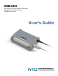
This user manual describes the STEVAL-MKI032V1, STM32-MEMS demonstration board which
serves as interface between the STM32™ demonstration board (STMicroelectronics™
STM3210B-EVAL, STM3210E-EVAL, IAR KickStart Kit™ for STM32) and the MEMS demonstration
board (any STEVAL-MKI0xxVx compatible with DIL24 socket).
The STM32-MEMS demonstration board comes with a development kit: a firmware package for the
STM32 microcontroller family, which includes a library, examples, demonstration applications and
application hints. The aim of this development kit is to provide a simple interface to analog and digital
MEMS accelerometers together with demonstration applications that utilize this interface.
The STM32 family of 32-bit Flash microcontrollers is based on the breakthrough ARM® Cortex™-M3,
a core specifically developed for embedded applications. The STM32 family benefits from the
Cortex-M3 architectural enhancements including the Thumb-2® instruction set to deliver improved
performance with better code density, significantly faster response to interrupts, all combined with
industry-leading power consumption.
The STM32 family is built to offer new degrees of freedom to MCU users. It offers a complete 32-bit
product range that combines high-performance, real-time, low-power and low-voltage operation, while
maintaining full integration and ease of development. Compatibility of pin-assignments, peripherals
and software across all STM32 devices is a core technical feature throughout this family of
microcontrollers.
The STM32 family of microcontrollers is supported by a complete range of high-end and low-cost
demonstration, software, debugging and programming tools. This complete line includes third-party
solutions that come complete with an integrated development environment and in-circuit
debugger/programmer featuring a JTAG application interface. Developers who are new to this family
and the Cortex core can also benefit from the range of starter kits that are specially designed to help
developers evaluate device features and start their own applications.
Sensors based on MEMS (micro electro-mechanical systems) technology are conquering many
market segments, ranging from mobile communication and computing to consumer electronics,
healthcare and industrial. ST offers a portfolio of MEMS-based linear accelerometers able to sense
acceleration or vibration in one, two and even three axes. Leveraging on proprietary MEMS technology
and worldwide recognized success on acceleration sensors, ST introduces new high-performance
MEMS gyroscope sensors.
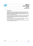
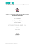
Figure 1.
July 2009
STEVAL-MKI032V1, STM32-MEMS demonstration board, top view
Doc ID 15703 Rev 1
1/42
www.st.com
Contents
UM0701
Contents
1
Introduction . . . . . . . . . . . . . . . . . . . . . . . . . . . . . . . . . . . . . . . . . . . . . . . . 1
2
Key features of the board . . . . . . . . . . . . . . . . . . . . . . . . . . . . . . . . . . . . . 6
3
General system description . . . . . . . . . . . . . . . . . . . . . . . . . . . . . . . . . . . 7
4
Board layout . . . . . . . . . . . . . . . . . . . . . . . . . . . . . . . . . . . . . . . . . . . . . . . . 8
5
System setup . . . . . . . . . . . . . . . . . . . . . . . . . . . . . . . . . . . . . . . . . . . . . . . 9
5.1
5.2
5.3
6
7
2/42
System setup with STM3210B-EVAL board . . . . . . . . . . . . . . . . . . . . . . . . 9
5.1.1
Connecting the STM32-MEMS board . . . . . . . . . . . . . . . . . . . . . . . . . . . 9
5.1.2
Setup for analog MEMS . . . . . . . . . . . . . . . . . . . . . . . . . . . . . . . . . . . . . 10
5.1.3
Setup for digital MEMS - SPI interface . . . . . . . . . . . . . . . . . . . . . . . . . 10
5.1.4
Setup for digital MEMS - I2C interface . . . . . . . . . . . . . . . . . . . . . . . . . . 11
5.1.5
Analog MEMS signals connected to STM32 pins . . . . . . . . . . . . . . . . . 12
5.1.6
Digital MEMS signals connected to STM32 pins . . . . . . . . . . . . . . . . . . 12
System setup with STM3210E-EVAL board . . . . . . . . . . . . . . . . . . . . . . . 12
5.2.1
Connecting the STM32-MEMS board . . . . . . . . . . . . . . . . . . . . . . . . . . 12
5.2.2
Setup for analog MEMS . . . . . . . . . . . . . . . . . . . . . . . . . . . . . . . . . . . . . 13
5.2.3
Setup for digital MEMS - SPI interface . . . . . . . . . . . . . . . . . . . . . . . . . 13
5.2.4
Setup for digital MEMS - I2C interface . . . . . . . . . . . . . . . . . . . . . . . . . . 14
5.2.5
Analog MEMS signals connected to STM32 pins . . . . . . . . . . . . . . . . . 15
5.2.6
Digital MEMS signals connected to STM32 pins . . . . . . . . . . . . . . . . . . 15
System setup with STM3210B-SK/IAR board . . . . . . . . . . . . . . . . . . . . . 15
5.3.1
Connecting the STM32-MEMS board . . . . . . . . . . . . . . . . . . . . . . . . . . 15
5.3.2
Setup for all MEMS . . . . . . . . . . . . . . . . . . . . . . . . . . . . . . . . . . . . . . . . 16
5.3.3
Analog MEMS signals connected to STM32 pins . . . . . . . . . . . . . . . . . 17
5.3.4
Digital MEMS signals connected to STM32 pins . . . . . . . . . . . . . . . . . . 17
Remote connection option . . . . . . . . . . . . . . . . . . . . . . . . . . . . . . . . . . . 18
6.1
Remote connection connector CN7 . . . . . . . . . . . . . . . . . . . . . . . . . . . . . 18
6.2
Analog axis selection - JP15 jumper . . . . . . . . . . . . . . . . . . . . . . . . . . . . 19
STM32-MEMS development kit . . . . . . . . . . . . . . . . . . . . . . . . . . . . . . . 20
Doc ID 15703 Rev 1
UM0701
Contents
7.1
MEMS Library . . . . . . . . . . . . . . . . . . . . . . . . . . . . . . . . . . . . . . . . . . . . . 20
7.2
MEMS Library functions reference . . . . . . . . . . . . . . . . . . . . . . . . . . . . . . 21
7.2.1
MEMS_ANL_Setup function . . . . . . . . . . . . . . . . . . . . . . . . . . . . . . . . . 22
7.2.2
MEMS_ANL_Drive_FS function . . . . . . . . . . . . . . . . . . . . . . . . . . . . . . 22
7.2.3
MEMS_ANL_Drive_PD function . . . . . . . . . . . . . . . . . . . . . . . . . . . . . . 23
7.2.4
MEMS_ANL_ADC_Restart function . . . . . . . . . . . . . . . . . . . . . . . . . . . 23
7.2.5
MEMS_ANL_Get_Axis function . . . . . . . . . . . . . . . . . . . . . . . . . . . . . . . 23
7.2.6
MEMS_DIG_Setup_Int1 function . . . . . . . . . . . . . . . . . . . . . . . . . . . . . . 24
7.2.7
MEMS_DIG_Setup_Int2 function . . . . . . . . . . . . . . . . . . . . . . . . . . . . . . 24
7.2.8
MEMS_SPI_Setup function . . . . . . . . . . . . . . . . . . . . . . . . . . . . . . . . . . 24
7.2.9
MEMS_SPI_WriteReg function . . . . . . . . . . . . . . . . . . . . . . . . . . . . . . . 25
7.2.10
MEMS_SPI_ReadReg function . . . . . . . . . . . . . . . . . . . . . . . . . . . . . . . 25
7.2.11
MEMS_SPI_SendFrame function . . . . . . . . . . . . . . . . . . . . . . . . . . . . . 26
7.2.12
MEMS_SPI_ReceiveFrame function . . . . . . . . . . . . . . . . . . . . . . . . . . . 26
7.2.13
MEMS_I2C_Setup function . . . . . . . . . . . . . . . . . . . . . . . . . . . . . . . . . . 27
7.2.14
MEMS_I2C_Set_Address function . . . . . . . . . . . . . . . . . . . . . . . . . . . . 27
7.2.15
MEMS_I2C_WriteReg function . . . . . . . . . . . . . . . . . . . . . . . . . . . . . . . 27
7.2.16
MEMS_I2C_ReadReg function . . . . . . . . . . . . . . . . . . . . . . . . . . . . . . . 28
7.2.17
MEMS_I2C_SendFrame function . . . . . . . . . . . . . . . . . . . . . . . . . . . . . 28
7.2.18
MEMS_I2C_ReceiveFrame function . . . . . . . . . . . . . . . . . . . . . . . . . . . 29
7.3
Example of MEMS Library usage: analog MEMS . . . . . . . . . . . . . . . . . . 30
7.4
Example of MEMS Library usage: digital MEMS over I2C . . . . . . . . . . . . 31
7.5
STM32-MEMS demonstration applications . . . . . . . . . . . . . . . . . . . . . . . 32
7.6
7.5.1
STM32-MEMS USB demonstration application . . . . . . . . . . . . . . . . . . . 33
7.5.2
STM32-MEMS LCD demonstration applications . . . . . . . . . . . . . . . . . . 34
Application tips: inclination measurement . . . . . . . . . . . . . . . . . . . . . . . . 35
7.6.1
Description . . . . . . . . . . . . . . . . . . . . . . . . . . . . . . . . . . . . . . . . . . . . . . . 35
7.6.2
Chip selection . . . . . . . . . . . . . . . . . . . . . . . . . . . . . . . . . . . . . . . . . . . . 37
Appendix A Bill of materials . . . . . . . . . . . . . . . . . . . . . . . . . . . . . . . . . . . . . . . . . 38
Appendix B Artwork prints . . . . . . . . . . . . . . . . . . . . . . . . . . . . . . . . . . . . . . . . . . 39
Appendix C Board schematic . . . . . . . . . . . . . . . . . . . . . . . . . . . . . . . . . . . . . . . . 40
Revision history . . . . . . . . . . . . . . . . . . . . . . . . . . . . . . . . . . . . . . . . . . . . . . . . . . . . 41
Doc ID 15703 Rev 1
3/42
List of tables
UM0701
List of tables
Table 1.
Table 2.
Table 3.
Table 4.
Table 5.
Table 6.
Table 7.
Table 8.
Table 9.
Table 10.
Table 11.
Table 12.
Table 13.
Table 14.
Table 15.
Table 16.
Table 17.
Table 18.
Table 19.
Table 20.
Table 21.
Table 22.
Table 23.
Table 24.
Table 25.
Table 26.
Table 27.
Table 28.
Table 29.
Table 30.
Table 31.
Table 32.
4/42
Connecting the STM32-MEMS board to the STM3210B-EVAL board . . . . . . . . . . . . . . . . . 9
Analog MEMS signals connected to STM32 pins . . . . . . . . . . . . . . . . . . . . . . . . . . . . . . . . 12
System setup with STM3210E-EVAL board . . . . . . . . . . . . . . . . . . . . . . . . . . . . . . . . . . . . 12
Connecting STM32-MEMS board to STM3210E-EVAL board . . . . . . . . . . . . . . . . . . . . . . 12
Analog MEMS signals connected to STM32 pins . . . . . . . . . . . . . . . . . . . . . . . . . . . . . . . . 15
Digital MEMS signals connected to STM32 pins . . . . . . . . . . . . . . . . . . . . . . . . . . . . . . . . 15
Connecting the STM32-MEMS board to the STM3210B-SK/IAR board. . . . . . . . . . . . . . . 16
Analog MEMS signals connected to STM32 pins . . . . . . . . . . . . . . . . . . . . . . . . . . . . . . . . 17
Digital MEMS signals connected to STM32 pins . . . . . . . . . . . . . . . . . . . . . . . . . . . . . . . . 17
CN7 connector pinout . . . . . . . . . . . . . . . . . . . . . . . . . . . . . . . . . . . . . . . . . . . . . . . . . . . . . 19
MEMS Library structure . . . . . . . . . . . . . . . . . . . . . . . . . . . . . . . . . . . . . . . . . . . . . . . . . . . 20
MEMS Library functions . . . . . . . . . . . . . . . . . . . . . . . . . . . . . . . . . . . . . . . . . . . . . . . . . . . 21
MEMS_ANL_Setup function . . . . . . . . . . . . . . . . . . . . . . . . . . . . . . . . . . . . . . . . . . . . . . . . 22
MEMS_ANL_Drive_FS function . . . . . . . . . . . . . . . . . . . . . . . . . . . . . . . . . . . . . . . . . . . . . 22
MEMS_ANL_Drive_PD function . . . . . . . . . . . . . . . . . . . . . . . . . . . . . . . . . . . . . . . . . . . . . 23
MEMS_ANL_ADC_Restart function . . . . . . . . . . . . . . . . . . . . . . . . . . . . . . . . . . . . . . . . . . 23
MEMS_ANL_Get_Axis function . . . . . . . . . . . . . . . . . . . . . . . . . . . . . . . . . . . . . . . . . . . . . 23
MEMS_DIG_Setup_Int1 function . . . . . . . . . . . . . . . . . . . . . . . . . . . . . . . . . . . . . . . . . . . . 24
MEMS_DIG_Setup_Int2 function . . . . . . . . . . . . . . . . . . . . . . . . . . . . . . . . . . . . . . . . . . . . 24
MEMS_SPI_Setup function . . . . . . . . . . . . . . . . . . . . . . . . . . . . . . . . . . . . . . . . . . . . . . . . 24
MEMS_SPI_WriteReg function. . . . . . . . . . . . . . . . . . . . . . . . . . . . . . . . . . . . . . . . . . . . . . 25
MEMS_SPI_ReadReg function . . . . . . . . . . . . . . . . . . . . . . . . . . . . . . . . . . . . . . . . . . . . . 25
MEMS_SPI_SendFrame function . . . . . . . . . . . . . . . . . . . . . . . . . . . . . . . . . . . . . . . . . . . . 26
MEMS_SPI_ReceiveFrame function . . . . . . . . . . . . . . . . . . . . . . . . . . . . . . . . . . . . . . . . . 26
MEMS_I2C_Setup function . . . . . . . . . . . . . . . . . . . . . . . . . . . . . . . . . . . . . . . . . . . . . . . . 27
MEMS_I2C_Set_Address function . . . . . . . . . . . . . . . . . . . . . . . . . . . . . . . . . . . . . . . . . . . 27
MEMS_I2C_WriteReg function . . . . . . . . . . . . . . . . . . . . . . . . . . . . . . . . . . . . . . . . . . . . . . 27
MEMS_I2C_ReadReg function. . . . . . . . . . . . . . . . . . . . . . . . . . . . . . . . . . . . . . . . . . . . . . 28
MEMS_I2C_SendFrame function . . . . . . . . . . . . . . . . . . . . . . . . . . . . . . . . . . . . . . . . . . . . 28
MEMS_I2C_ReceiveFrame function . . . . . . . . . . . . . . . . . . . . . . . . . . . . . . . . . . . . . . . . . 29
Bill of material . . . . . . . . . . . . . . . . . . . . . . . . . . . . . . . . . . . . . . . . . . . . . . . . . . . . . . . . . . . 38
Document revision history . . . . . . . . . . . . . . . . . . . . . . . . . . . . . . . . . . . . . . . . . . . . . . . . . 41
Doc ID 15703 Rev 1
UM0701
List of figures
List of figures
Figure 1.
STEVAL-MKI032V1, STM32-MEMS demonstration board, top view . . . . . . . . . . . . . . . . . . 1
Figure 2.
System with STM32-MEMS demonstration board . . . . . . . . . . . . . . . . . . . . . . . . . . . . . . . . 7
Figure 3.
STM32-MEMS demonstration board layout . . . . . . . . . . . . . . . . . . . . . . . . . . . . . . . . . . . . . 8
Figure 4.
Connecting MEMS demonstration board to STM32-MEMS board . . . . . . . . . . . . . . . . . . . . 9
Figure 5.
STM3210B-EVAL board with STM32-MEMS board connected . . . . . . . . . . . . . . . . . . . . . 10
Figure 6.
Setup for analog MEMS . . . . . . . . . . . . . . . . . . . . . . . . . . . . . . . . . . . . . . . . . . . . . . . . . . . 10
Figure 7.
Setup for digital MEMS - SPI interface . . . . . . . . . . . . . . . . . . . . . . . . . . . . . . . . . . . . . . . . 11
Figure 8.
Setup for digital MEMS - I2C interface . . . . . . . . . . . . . . . . . . . . . . . . . . . . . . . . . . . . . . . . 11
Figure 9.
STM3210E-EVAL board with STM32-MEMS board connected . . . . . . . . . . . . . . . . . . . . . 13
Figure 10. Setup for analog MEMS . . . . . . . . . . . . . . . . . . . . . . . . . . . . . . . . . . . . . . . . . . . . . . . . . . . 13
Figure 11. Setup for digital MEMS - SPI interface . . . . . . . . . . . . . . . . . . . . . . . . . . . . . . . . . . . . . . . . 14
Figure 12. Setup for digital MEMS - I2C interface . . . . . . . . . . . . . . . . . . . . . . . . . . . . . . . . . . . . . . . . 14
Figure 13. Connecting the STM32-MEMS board to the STM3210B-SK/IAR board. . . . . . . . . . . . . . . 15
Figure 14. STM3210B-SK/IAR board with STM32-MEMS board connected . . . . . . . . . . . . . . . . . . . . 16
Figure 15. Setup for all MEMS . . . . . . . . . . . . . . . . . . . . . . . . . . . . . . . . . . . . . . . . . . . . . . . . . . . . . . . 16
Figure 16. Remote connection . . . . . . . . . . . . . . . . . . . . . . . . . . . . . . . . . . . . . . . . . . . . . . . . . . . . . . . 18
Figure 17. Remote connection connector CN7 . . . . . . . . . . . . . . . . . . . . . . . . . . . . . . . . . . . . . . . . . . 18
Figure 18. Analog axis selection using the JP15 jumper . . . . . . . . . . . . . . . . . . . . . . . . . . . . . . . . . . . 19
Figure 19. MEMS USB Reader Windows GUI application. . . . . . . . . . . . . . . . . . . . . . . . . . . . . . . . . . 34
Figure 20. STM32-MEMS LCD demonstration application running on STM3210B_EVAL (left) and
STM3210B_SK_IAR (right) . . . . . . . . . . . . . . . . . . . . . . . . . . . . . . . . . . . . . . . . . . . . . . . . . . . . . . . . . . . 35
Figure 21. Earth's gravity . . . . . . . . . . . . . . . . . . . . . . . . . . . . . . . . . . . . . . . . . . . . . . . . . . . . . . . . . . . 35
Figure 22. Inclination measurement. . . . . . . . . . . . . . . . . . . . . . . . . . . . . . . . . . . . . . . . . . . . . . . . . . . 36
Figure 23. Sinus and Cosinus functions . . . . . . . . . . . . . . . . . . . . . . . . . . . . . . . . . . . . . . . . . . . . . . . 36
Figure 24. STM32-MEMS demonstration board PCB (top and bottom layers) . . . . . . . . . . . . . . . . . . 39
Figure 25. Board schematic . . . . . . . . . . . . . . . . . . . . . . . . . . . . . . . . . . . . . . . . . . . . . . . . . . . . . . . . . 40
Doc ID 15703 Rev 1
5/42
Key features of the board
2
Key features of the board
●
●
●
●
6/42
UM0701
Compatible with the following demonstration boards.
–
ST STM3210B-EVAL - ST demonstration board implementing the complete range
of peripherals and features for the STM32F10xxB (128 KB) medium-density
devices.
–
ST STM3210E-EVAL - ST demonstration board implementing the complete range
of peripherals and features for the STM32F10xxE (512 KB) high-density devices.
–
IAR KickStart Kit™ for STM32 (STM3210B-SK/IAR) - full-featured demonstration
board with STM32F103B microcontroller, standalone J-Link
debugger/programmer, IAR Embedded Workbench® for ARM (EWARM)
development environment, IAR C/C++ compiler.
Compatible with all STEVAL-MKI0xxVx MEMS accelerometer demonstration boards
suitable for DIL24 sockets. Recommended boards are:
–
digital MEMS accelerometers: STEVAL-MKI013V1 (LIS302DL), STEVALMKI009V1 (LIS3LV02DL),
–
analog MEMS accelerometers: STEVAL-MKI015V1 (LIS344ALH), STEVALMKI018V1 (LIS244AL), STEVAL-MKI020V1 (LIS302SG),
Options for remote connection using two STM32-MEMS demonstration boards.
–
Standard 20-pin ribbon cable with 2.54 mm pitch connectors with all signals
–
Coax cable with standard BNC connector for connection of one analog signal MEMS axis selectable by jumper
STM32-MEMS development kit firmware package for STM32 included.
–
MEMS Library: set of functions, data structures and constants used to manage
a MEMS sensor. Examples of usage of the MEMS Library.
–
Demonstration applications that utilize the MEMS Library showing how to acquire
data from a sensor and send them to a PC over USB or how to display the data
using an LCD. Several demonstration applications show utilization of interrupts
generated by digital MEMS.
–
Application hints on inclination measurements.
Doc ID 15703 Rev 1
UM0701
3
General system description
General system description
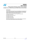
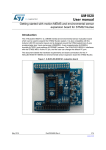
The STM32-MEMS demonstration board serves to connect data and control signals of
a MEMS sensor to pins of the STM32 microcontroller.
The STM32-MEMS board is designed to fit on particular connectors of compatible STM32
demonstration boards. The compatible boards are: STM3210B-EVAL board (with mediumdensity STM32 MCU), STM3210E-EVAL board (with high-density STM32 MCU) and
STM3210B-SK/IAR (for medium-density STM32 MCU).
The STM32-MEMS board has a DIL24 socket to connect any STEVAL-MKI0xxVx MEMS
demonstration board compatible with the socket. The recommended boards are: digital
MEMS accelerometers STEVAL-MKI013V1 (LIS302DL) and STEVAL-MKI009V1
(LIS3LV02DL), and analog MEMS accelerometers STEVAL-MKI015V1 (LIS344ALH),
STEVAL-MKI018V1 (LIS244AL) and STEVAL-MKI020V1 (LIS302SG).
The system with STM32-MEMS board offers full control over the MEMS sensor. For analog
sensors all axes, power-down and full-scale signals are available. For digital sensors both
SPI and I2C interfaces are usable as well as interrupt lines.
To run the system, the STM32-MEMS board must be connected on one side to an STM32
demonstration board, and on the other side to a MEMS demonstration board. The jumpers
on the STM32-MEMS demonstration board have to be fitted properly. In some cases, minor
changes may have to be made to the STM32 demonstration board. All system settings are
described in detail in the following chapters.
Figure 2.
System with STM32-MEMS demonstration board
STEVAL - MKI0xxVx
MEMS demonstration
board
STM32- MEMS board
STM32 demonstration board
STEVAL - MKI032V1
STM3210B - EVAL
STM3210E - EVAL
STM3210B - SK/IAR
AM00446
Doc ID 15703 Rev 1
7/42
Board layout
4
Board layout
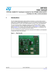
Figure 3.
8/42
UM0701
STM32-MEMS demonstration board layout
Doc ID 15703 Rev 1
UM0701
5
System setup
System setup
The system consists of three boards: the STM32 demonstration board, the STM32-MEMS
demonstration board and the MEMS demonstration board. The set-up of the system can be
split into three main steps.
1.
Set-up of the STM32 demonstration board. In some cases, minor changes may have to
be made to the board.
2.
Set-up of the jumpers on the STM32-MEMS board.
3.
Connection of the STM32-MEMS board to the STM32 demonstration board.
4.
Connection of the MEMS demonstration board to the STM32-MEMS board.
Steps 1 to 3 vary according to the type of STM32 demonstration board and MEMS
demonstration board used. They are described in the following chapters.
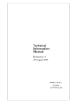
Regarding step 4: all MEMS demonstration boards compatible with the DIL24 socket can be
connected to the STM32-MEMS board. The correct orientation of the board is depicted in
Figure 4 by the ST logo printed on the top side of the STM32-MEMS board.
Figure 4.
Connecting MEMS demonstration board to STM32-MEMS board
5.1
System setup with STM3210B-EVAL board
5.1.1
Connecting the STM32-MEMS board
Table 1.
Note:
Connecting the STM32-MEMS board to the STM3210B-EVAL board
Pin of STM32-MEMS board
Connected to pin of STM3210B-EVAL
CN1-1
CN12-1
CN2-1
CN13-1
CN4-1
JP11-1
The CN4 connector of the STM32-MEMS board is connected to the JP11 jumper of the
STM3210B-EVAL board in order to distribute VCC to the MEMS sensor. In this setup, the
JP16 jumper of the STM32-MEMS board takes over the VBAT selection functionality of the
JP11 jumper of the STM3210B-EVAL board.
Doc ID 15703 Rev 1
9/42
System setup
Figure 5.
5.1.2
UM0701
STM3210B-EVAL board with STM32-MEMS board connected
Setup for analog MEMS
Position the JP1, JP2 and JP3 jumpers on the STM32-MEMS board. No modification is
needed on the STM3210B-EVAL board.
Figure 6.
5.1.3
Setup for analog MEMS
Setup for digital MEMS - SPI interface
Position the JP7 jumper on the STM32-MEMS board.
If Int1 signal is used
Position the JP10 jumper on the STM32-MEMS board.
The CN13-14 pin of the STM3210B-EVAL is also used by the right joystick. If the joystick is
required, remove R75 from the STM3210B-EVAL board.
If Int2 signal is used
Position the JP11 jumper on the STM32-MEMS board.
10/42
Doc ID 15703 Rev 1
UM0701
System setup
The CN13-4-pin of the STM3210B-EVAL is also used by the Tamper button. The Tamper
button cannot be used when using the Int2 signal.
Figure 7.
5.1.4
Setup for digital MEMS - SPI interface
Setup for digital MEMS - I2C interface
Position the JP7 and JP12 jumpers on the STM32-MEMS board.
If Int1 signal is used
Position the JP10 jumper on the STM32-MEMS board.
The CN13-14-pin of the STM3210B-EVAL is also used by the right joystick. If the joystick is
required, remove R75 from the STM3210B-EVAL board.
If Int2 signal is used
Position the JP11 jumper on the STM32-MEMS board.
The CN13-4-pin of the STM3210B-EVAL is also used by the Tamper button. The Tamper
button cannot be used when using the Int2 signal.
Figure 8.
Setup for digital MEMS - I2C interface
Doc ID 15703 Rev 1
11/42
System setup
5.1.5
Analog MEMS signals connected to STM32 pins
Table 2.
5.1.6
UM0701
Analog MEMS signals connected to STM32 pins
Analog MEMS signal
STM32 pin
FS
PE3
PD
PE2
VOUTX
PC0
VOUTY
PC1
VOUTZ
PC3
Digital MEMS signals connected to STM32 pins
Table 3.
System setup with STM3210E-EVAL board
Common signals
SPI signals
I2C signals
Digital MEMS signal
STM32 pin
CS
PE6
Int1
PE0
Int2
PC13
SCK
PA5
SDI
PA7
SDO
PA6
SCL
PB6
SDA
PB7
Note:
Some digital MEMS use SDO as the LSB of their I2C address.
5.2
System setup with STM3210E-EVAL board
5.2.1
Connecting the STM32-MEMS board
Table 4.
12/42
Connecting STM32-MEMS board to STM3210E-EVAL board
Pin of STM32-MEMS board
Connected to pin of STM3210E-EVAL
CN1-1
CN10-33
CN2-1
CN11-33
Doc ID 15703 Rev 1
UM0701
System setup
Figure 9.
5.2.2
STM3210E-EVAL board with STM32-MEMS board connected
Setup for analog MEMS
Position the JP5, JP13 and JP14 jumpers on the STM32-MEMS board.
No modification is needed on the STM3210E-EVAL board.
Figure 10. Setup for analog MEMS
5.2.3
Setup for digital MEMS - SPI interface
Position the JP5, JP6, JP9 and JP11 jumpers on the STM32-MEMS board.
If Int1 signal is used
Position the JP10 jumper on the STM32-MEMS board.
Remove the SD card from the CN13 card socket on the STM3210E-EVAL board.
Doc ID 15703 Rev 1
13/42
System setup
UM0701
Figure 11. Setup for digital MEMS - SPI interface
5.2.4
Setup for digital MEMS - I2C interface
Position the JP5, JP8, JP9 and JP11 jumpers on the STM32-MEMS board.
Remove R32 from the STM3210E-EVAL board.
If Int1 signal is used
Position the JP10 jumper on the STM32-MEMS board.
Remove the SD card from the CN13 card socket on the STM3210E-EVAL board.
Figure 12. Setup for digital MEMS - I2C interface
14/42
Doc ID 15703 Rev 1
UM0701
5.2.5
System setup
Analog MEMS signals connected to STM32 pins
Table 5.
5.2.6
Analog MEMS signals connected to STM32 pins
Analog MEMS signal
STM32 pin
FS
PG0
PD
PF13
VOUTX
PB0
VOUTY
PC5
VOUTZ
PB1
Digital MEMS signals connected to STM32 pins
Table 6.
Digital MEMS signals connected to STM32 pins
Digital MEMS signal
Common signals
SPI signals
I2C signals
STM32 pin
CS
PG1
Int1
PF11
Int2
PE8
SCK
PB3
SDI
PB5
SDO
PB4
SCL
PB8
SDA
PB9
Note:
Some digital MEMS use the SDO as the LSB of their I2C address.
5.3
System setup with STM3210B-SK/IAR board
5.3.1
Connecting the STM32-MEMS board
Figure 13. Connecting the STM32-MEMS board to the STM3210B-SK/IAR board
Doc ID 15703 Rev 1
15/42
System setup
Table 7.
UM0701
Connecting the STM32-MEMS board to the STM3210B-SK/IAR board
Pin of STM32-MEMS board
Connected to pin of STM3210B-SK/IAR
CN1-2
I2C2_SDA pin on 13-pin single row header next to
LCD display
CN3-1
WP pin on 32-pin dual row header next to LEDs
Figure 14. STM3210B-SK/IAR board with STM32-MEMS board connected
5.3.2
Setup for all MEMS
Position the JP4 and JP5 jumpers on the STM32-MEMS board.
To use the analog MEMS, remove R36, R37 and R59 from the STM3210B-SK/IAR board.
Figure 15. Setup for all MEMS
16/42
Doc ID 15703 Rev 1
UM0701
5.3.3
System setup
Analog MEMS signals connected to STM32 pins
Table 8.
5.3.4
Analog MEMS signals connected to STM32 pins
Analog MEMS signal
STM32 pin
FS
PA9
PD
PA10
VOUTX
PA5
VOUTY
PA6
VOUTZ
PA7
Digital MEMS signals connected to STM32 pins
Table 9.
Digital MEMS signals connected to STM32 pins
Common signals
SPI signals
I2C signals
Note:
Digital MEMS signal
STM32 pin
CS
PB12
Int1
PB11
Int2
PB10
SCK
PB13
SDI
PB15
SDO
PB14
SCL
PB6
SDA
PB7
Some digital MEMS use the SDO as the LSB of their I2C address.
Doc ID 15703 Rev 1
17/42
Remote connection option
6
UM0701
Remote connection option
The remote connection option can be used when the MEMS sensor needs to be placed in a
position where the STM32 demonstration board does not fit, for example for motor vibration
measurement applications. Two STM32-MEMS demonstration boards are needed to use
the remote connection option. One of the boards is connected to the STM32 demonstration
board, while the other is connected to the MEMS demonstration board. The two
STM32-MEMS boards are interconnected using a 20-pin ribbon cable with
10 x 2 2.54 mm pitch sockets connected to the CN7 connectors. It is possible to improve the
transition of one analog axis by using a coax cable connected to the CN8 BNC connectors.
The JP15 jumper selects the analog axis that is connected to the CN8 BNC connector.
Figure 16. Remote connection
MEMS
demonstration
board
STM32 - MEMS board
STM32 - MEMS board
STM32 demonstration board
AM00447
6.1
Remote connection connector CN7
This connector allows two STM32-MEMS boards to be connected together.
Figure 17. Remote connection connector CN7
2
4
6
8 10 12 14 16 18 20
1
3
5
7
9 11 13 15 17 19
AM00448
18/42
Doc ID 15703 Rev 1
UM0701
Remote connection option
Table 10.
6.2
CN7 connector pinout
Pin
Signal
Pin
Signal
1
GND
2
3.3 V DC
3
NC
4
Int1
5
VOUTX
6
Int2
7
NC
8
SCL
9
VOUTY
10
SDx
11
NC
12
SDO
13
VOUTZ
14
CS
15
PD
16
NC
17
FS
18
NC
19
GND
20
3.3 V DC
Analog axis selection - JP15 jumper
This jumper is used to select which analog axis is connected to the CN8 BNC connector.
Figure 18. Analog axis selection using the JP15 jumper
JP15
X axis selected
X
Y axis selected
Y
Z axis selected
Z
Analog axis selection
AM00449
Doc ID 15703 Rev 1
19/42
STM32-MEMS development kit
7
UM0701
STM32-MEMS development kit
The STM32-MEMS development kit provides a simple programming interface between the
STM32 microcontroller and analog or digital MEMS accelerometers together with
demonstration applications that utilize this interface.
The following sections describe all the components that make up the STM32-MEMS
development kit, including:
7.1
●
the MEMS Library,
●
examples of MEMS Library usage,
●
the STM32-MEMS USB demonstration application,
●
the STM32-MEMS LCD demonstration applications,
●
application tips on inclination measurements.
MEMS Library
This section describes the firmware interface (called MEMS Library) used to manage the
MEMS sensor attached to the STEVAL-MKI032V1, STM32-MEMS demonstration board by
the STM32 microcontroller.
The main purpose of this firmware library is to provide resources to ease the development of
applications using a MEMS sensor. The MEMS Library is designed to be used with the
STM32-MEMS demonstration board. However, it is parameterized and therefore can be
easily adapted to any other hardware configuration.
Note:
When using the MEMS Library on the STM3210E_EVAL board, some JTAG signals of the
STM32 MCU can be remapped to the GPIO functionality by the library functions
MEMS_SPI_Setup and MEMS_I2C_Setup. This means that after the program startup,
debugging or flashing the MCU via the JTAG will not be possible. In order to be able to
re-flash the MCU via the JTAG, you have to power-up the board with BOOT0 and BOOT1
switches set to position 1 and then flash the MCU. Finally, to run the program from the
Flash, power-up the board with switches BOOT0 and BOOT1 set to position 0.
Table 11 presents the MEMS Library structure.
Table 11.
MEMS Library structure
File
20/42
Description
stm32_mems.h
Constants and types related to MEMS sensors.
stm32_mems_adapter.h
Constants for configuration and utilization of STM32 peripherals related
to the MEMS sensor attached to the STM32-MEMS demonstration
board.
stm32_mems_adapter.c
Functions for configuration and utilization of STM32 peripherals related
to the MEMS sensor attached to the STM32-MEMS demonstration
board.
Doc ID 15703 Rev 1
UM0701
STM32-MEMS development kit
stm32_mems.h
This file provides constants containing the I2C address, register addresses and who_am_i
value related to several digital MEMS sensors (LIS302DL, LIS3LV02DL). It also defines
a type used to store data from the axis of a MEMS accelerometer.
stm32_mems_adapter.h
This file provides constants for configuration and utilization of STM32 peripherals related to
the MEMS sensor attached to the STM32-MEMS demonstration board. The constants
correspond to pins and peripherals of the STM32 microcontroller connected to the MEMS
sensor.
There are three sets of constants. Each set contains the same constants but for different
STM32 demonstration boards. To choose a particular set, one of the three #define
statements at the beginning of the file must be uncommented. The #define statements
are:
#define STM3210B_EVAL
#define STM3210E_EVAL
#define STM3210B_SK_IAR
For example, the correct definition to choose a set of constants for the ST STM3210B-EVAL
demonstration board is:
#define STM3210B_EVAL
// #define STM3210E_EVAL
// #define STM3210B_SK_IAR
stm32_mems_adapter.c
This file provides functions for configuration and utilization of STM32 peripherals related to
the MEMS sensor attached to the STM32-MEMS demonstration board.
7.2
MEMS Library functions reference
Table 12 lists the MEMS Library functions.
Table 12.
MEMS Library functions
Function name
Description
MEMS_ANL_Setup
Sets-up all peripherals related to the analog MEMS.
MEMS_ANL_Drive_FS
Drives the FS pin of the analog MEMS.
MEMS_ANL_Drive_PD
Drives the PD pin of the analog MEMS.
MEMS_ANL_ADC_Restart
Restarts the ADC and DMA.
MEMS_ANL_Get_Axis
Gets values of all MEMS axes.
MEMS_DIG_Setup_Int1
Enables or disables EXTI for the Int1 interrupt signal.
MEMS_DIG_Setup_Int2
Enables or disables EXTI for the Int2 interrupt signal.
MEMS_SPI_Setup
Sets-up all peripherals related to the digital MEMS connected over the SPI.
Doc ID 15703 Rev 1
21/42
STM32-MEMS development kit
Table 12.
UM0701
MEMS Library functions
Function name
Description
MEMS_SPI_WriteReg
Writes data to the MEMS register over the SPI.
MEMS_SPI_ReadReg
Reads data to the MEMS register over the SPI.
MEMS_SPI_SendFrame
Sends one frame over the SPI.
MEMS_SPI_ReceiveFrame
Receives one frame over the SPI.
MEMS_I2C_Setup
Sets-up all peripherals related to the digital MEMS connected over the I2C.
MEMS_I2C_Set_Address
Sets the address of the MEMS for I2C communication.
MEMS_I2C_WriteReg
Writes data to the MEMS register over the I2C.
MEMS_I2C_ReadReg
Reads data from the MEMS register over the I2C.
MEMS_I2C_SendFrame
Sends one frame over the I2C.
MEMS_I2C_ReceiveFrame
Receives one frame over the I2C.
7.2.1
MEMS_ANL_Setup function
Table 13 describes the MEMS_ANL_Setup function.
Table 13.
MEMS_ANL_Setup function
Function name
7.2.2
MEMS_ANL_Setup
Function prototype
void MEMS_ANL_Setup (void)
Description
Sets-up all peripherals related to the analog MEMS.
Input parameter
None
Output parameter
None
Return parameter
None
MEMS_ANL_Drive_FS function
Table 14 describes the MEMS_ANL_Drive_FS function.
Table 14.
MEMS_ANL_Drive_FS function
Function name
22/42
MEMS_ANL_Drive_FS
Function prototype
void MEMS_ANL_Drive_FS (BitAction BitVal)
Description
Drives the FS pin of the analog MEMS.
Input parameter
BitVal: new value of the FS pin
BitVal must be one of the BitAction enum values:
– Bit_RESET: clears the port pin
– Bit_SET: sets the port pin
Output parameter
None
Return parameter
None
Doc ID 15703 Rev 1
UM0701
7.2.3
STM32-MEMS development kit
MEMS_ANL_Drive_PD function
Table 15 describes the MEMS_ANL_Drive_PD function.
Table 15.
MEMS_ANL_Drive_PD function
Function name
7.2.4
MEMS_ANL_Drive_PD
Function prototype
void MEMS_ANL_Drive_PD (BitAction BitVal)
Description
Drives the PD pin of the analog MEMS.
Input parameter
BitVal: new value of the PD pin
BitVal must be one of the BitAction enum values:
– Bit_RESET: clears the port pin
– Bit_SET: sets the port pin
Output parameter
None
Return parameter
None
MEMS_ANL_ADC_Restart function
Table 16 describes the MEMS_ANL_ADC_Restart function.
Table 16.
MEMS_ANL_ADC_Restart function
Function name
7.2.5
MEMS_ANL_ADC_Restart
Function prototype
void MEMS_ANL_ADC_Restart(void)
Description
Restarts the ADC and DMA.
Input parameter
None
Output parameter
None
Return parameter
None
MEMS_ANL_Get_Axis function
Table 17 describes the MEMS_ANL_Get_Axis function.
Table 17.
MEMS_ANL_Get_Axis function
Function name
MEMS_ANL_Get_Axis
Function prototype
void MEMS_ANL_Get_Axis(s16 *x, s16 *y, s16 *z)
Description
Gets values of all MEMS axes.
Input parameter
None
Output parameter1
x: value of x axis
Output parameter2
y: value of y axis
Output parameter3
z: value of z axis
Return parameter
None
Doc ID 15703 Rev 1
23/42
STM32-MEMS development kit
7.2.6
UM0701
MEMS_DIG_Setup_Int1 function
Table 18 describes the MEMS_DIG_Setup_Int1 function.
Table 18.
MEMS_DIG_Setup_Int1 function
Function name
7.2.7
MEMS_DIG_Setup_Int1
Function prototype
void MEMS_DIG_Setup_Int1
(FunctionalState NewState)
Description
Enables or disables EXTI for the Int1 interrupt signal.
Input parameter
NewState: new state of the interrupt.
This parameter can be ENABLE or DISABLE
Output parameter
None
Return parameter
None
MEMS_DIG_Setup_Int2 function
Table 19 describes the MEMS_DIG_Setup_Int2 function.
Table 19.
MEMS_DIG_Setup_Int2 function
Function name
7.2.8
MEMS_DIG_Setup_Int2
Function prototype
void MEMS_DIG_Setup_Int2
(FunctionalState NewState)
Description
Enables or disables EXTI for the Int2 interrupt signal.
Input parameter
NewState: new state of the interrupt.
This parameter can be ENABLE or DISABLE
Output parameter
None
Return parameter
None
MEMS_SPI_Setup function
Table 20 describes the MEMS_SPI_Setup function.
Table 20.
MEMS_SPI_Setup function
Function name
24/42
MEMS_SPI_Setup
Function prototype
void MEMS_SPI_Setup (void)
Description
Sets-up all peripherals related to the digital MEMS connected over
SPI.
Input parameter
None
Output parameter
None
Return parameter
None
Doc ID 15703 Rev 1
UM0701
7.2.9
STM32-MEMS development kit
MEMS_SPI_WriteReg function
Table 21 describes the MEMS_SPI_WriteReg function.
Table 21.
MEMS_SPI_WriteReg function
Function name
7.2.10
MEMS_SPI_WriteReg
Function prototype
ErrorStatus MEMS_SPI_WriteReg
(u8 RegAddress, u8 Data)
Description
Writes data to the MEMS register over SPI.
Input parameter1
RegAddress: address of register
Input parameter2
Data: data to be written
Output parameter
None
Return parameter
An ErrorStatus enumeration value:
– SUCCESS: register written
– ERROR: register not written
MEMS_SPI_ReadReg function
Table 22 describes the MEMS_SPI_ReadReg function.
Table 22.
MEMS_SPI_ReadReg function
Function name
MEMS_SPI_ReadReg
Function prototype
ErrorStatus MEMS_SPI_ReadReg
(u8 RegAddress, u8 *Data)
Description
Reads data to the MEMS register over SPI.
Input parameter
RegAddress: address of register
Output parameter
Data: data read
Return parameter
An ErrorStatus enumeration value:
– SUCCESS: register written
– ERROR: register not written
Doc ID 15703 Rev 1
25/42
STM32-MEMS development kit
7.2.11
UM0701
MEMS_SPI_SendFrame function
Table 23 describes the MEMS_SPI_SendFrame function.
Table 23.
MEMS_SPI_SendFrame function
Function name
7.2.12
MEMS_SPI_SendFrame
Function prototype
ErrorStatus MEMS_SPI_SendFrame
(u8 RegAddress, u8 *pBuffer, u8 NoOfBytes)
Description
Sends one frame over SPI.
Input parameter1
RegAddress: address of register
Input parameter2
pBuffer: pointer to buffer with data
Input parameter3
NoOfBytes: number of bytes to be sent
Output parameter
None
Return parameter
An ErrorStatus enumeration value:
– SUCCESS: register written
– ERROR: register not written
MEMS_SPI_ReceiveFrame function
Table 24 describes the MEMS_SPI_ReceiveFrame function.
Table 24.
MEMS_SPI_ReceiveFrame function
Function name
26/42
MEMS_SPI_ReceiveFrame
Function prototype
ErrorStatus MEMS_SPI_ReceiveFrame
(u8 RegAddress, u8 *pBuffer, u8 NoOfBytes)
Description
Receives one frame over SPI.
Input parameter1
RegAddress: address of source register
Input parameter2
NoOfBytes: number of bytes to be received
Output parameter
pBuffer: pointer to output buffer
Return parameter
An ErrorStatus enumeration value:
– SUCCESS: register written
– ERROR: register not written
Doc ID 15703 Rev 1
UM0701
7.2.13
STM32-MEMS development kit
MEMS_I2C_Setup function
Table 25 describes the MEMS_I2C_Setup function.
.
Table 25.
MEMS_I2C_Setup function
Function name
7.2.14
MEMS_I2C_Setup
Function prototype
void MEMS_I2C_Setup (u8 MEMS_I2C_Address)
Description
Sets up all peripherals related to digital MEMS connected over I2C.
Input parameter
MEMS_I2C_Address: I2C address of MEMS
Output parameter
None
Return parameter
None
MEMS_I2C_Set_Address function
Table 26 describes the MEMS_I2C_Set_Address function.
Table 26.
MEMS_I2C_Set_Address function
Function name
7.2.15
MEMS_I2C_Set_Address
Function prototype
void MEMS_I2C_Set_Address (u8 MEMS_I2C_Address)
Description
Sets MEMS address for I2C communication.
Input parameter
MEMS_I2C_Address: I2C address of MEMS
Output parameter
None
Return parameter
None
MEMS_I2C_WriteReg function
Table 27 describes the MEMS_I2C_WriteReg function.
Table 27.
MEMS_I2C_WriteReg function
Function name
MEMS_I2C_WriteReg
Function prototype
ErrorStatus MEMS_I2C_WriteReg
(u8 RegAddress, u8 Data)
Description
Writes data to the MEMS register over I2C.
Input parameter1
RegAddress: address of register
Input parameter2
Data: data to be written
Output parameter
None
Return parameter
An ErrorStatus enumeration value:
– SUCCESS: register written
– ERROR: register not written
Doc ID 15703 Rev 1
27/42
STM32-MEMS development kit
7.2.16
UM0701
MEMS_I2C_ReadReg function
Table 28 describes the MEMS_I2C_ReadReg function.
Table 28.
MEMS_I2C_ReadReg function
Function name
7.2.17
MEMS_I2C_ReadReg
Function prototype
ErrorStatus MEMS_I2C_ReadReg
(u8 RegAddress, u8 *Data)
Description
Reads data to the MEMS register over I2C.
Input parameter
RegAddress: address of register
Output parameter
Data: data read
Return parameter
An ErrorStatus enumeration value:
– SUCCESS: register written
– ERROR: register not written
MEMS_I2C_SendFrame function
Table 29 describes the MEMS_I2C_SendFrame function.
Table 29.
MEMS_I2C_SendFrame function
Function name
28/42
MEMS_I2C_SendFrame
Function prototype
ErrorStatus MEMS_I2C_SendFrame
(u8 RegAddress, u8 *pBuffer, u8 NoOfBytes)
Description
Sends one frame over I2C.
Input parameter1
RegAddress: address of register
Input parameter2
pBuffer: pointer to buffer with data
Input parameter3
NoOfBytes: number of bytes to be sent
Output parameter
None
Return parameter
An ErrorStatus enumeration value:
– SUCCESS: register written
– ERROR: register not written
Doc ID 15703 Rev 1
UM0701
7.2.18
STM32-MEMS development kit
MEMS_I2C_ReceiveFrame function
Table 30 describes the MEMS_I2C_ReceiveFrame function.
Table 30.
MEMS_I2C_ReceiveFrame function
Function name
MEMS_I2C_ReceiveFrame
Function prototype
ErrorStatus MEMS_I2C_ReceiveFrame
(u8 RegAddress, u8 *pBuffer, u8 NoOfBytes)
Description
Receives one frame over I2C.
Input parameter1
RegAddress: address of source register
Input parameter2
NoOfBytes: number of bytes to be received
Output parameter
pBuffer: pointer to output buffer
Return parameter
An ErrorStatus enumeration value:
– SUCCESS: register written
– ERROR: register not written
Doc ID 15703 Rev 1
29/42
STM32-MEMS development kit
7.3
UM0701
Example of MEMS Library usage: analog MEMS
This section shows an example of a main function to set-up and read data from an analog
MEMS. Do not forget to set-up the defines in the stm32_mems_adapter.h file according to
the STM32 demonstration board used.
/* This main function sets up and reads data from any analog MEMS */
int main (void)
{
s16 ADC_DataValue[3];
/* Setup STM32 system clock and other peripherals here */
/* … */
/* Setup all peripherals related to analog MEMS */
MEMS_ANL_Setup();
/* Wait 40ms after reset to let the MEMS turn on from power down*/
Delay(40);
/* Restart ADC and DMA */
MEMS_ANL_ADC_Restart();
while (1)
{
/* Read all analog MEMS axis */
MEMS_ANL_Get_Axis(&ADC_DataValue[0],&ADC_DataValue[1],&ADC_DataValu
e[2]);
/* Use the data */
/* … */
}
return 0;
}
30/42
Doc ID 15703 Rev 1
UM0701
7.4
STM32-MEMS development kit
Example of MEMS Library usage: digital MEMS over I2C
This section shows an example of the main function to set-up and read data from a digital
MEMS over the I2C. Minor modifications (mainly replacing I2C in names of functions with
SPI) would make this example work over an SPI interface. Do not forget to set-up the
defines in the stm32_mems_adapter.h file according to the STM32 demonstration board
used.
/* This main function sets-up and reads data from LIS302DL digital
MEMS */
int main(void)
{
u8 i;
u8 i2c_buffer[6];
t_mems_data MEMS_Data={0, 0, 0, 0, 0, 0};
/* Setup STM32 system clock and other peripherals here */
/* … */
/* Setup all peripherals related to digital MEMS */
MEMS_I2C_Setup(LIS302DL_I2C_ADDR);
/* Wait 40ms after reset to let the MEMS turn on from power down*/
Delay(40);
/* Check who_am_i value */
MEMS_I2C_ReadReg(LIS302DL_WHO_AM_I, &i);
if (i != LIS302DL_WHO_AM_I_VALUE) return 1;
/* Initialize registers of LIS302DL */
/* IMPORTANT NOTE: These settings differ for different MEMS part
numbers! */
/* Following are settings for LIS302DL. */
/* CTRL_REG1 Register - Data rate 400Hz, power up, enable all axes
*/
MEMS_I2C_WriteReg (LIS302DL_CTRL_REG1, 0x47);
while (1)
{
Doc ID 15703 Rev 1
31/42
STM32-MEMS development kit
UM0701
/* Read all MEMS axis */
MEMS_I2C_ReceiveFrame (LIS302DL_OUTX, i2c_buffer, 6);
MEMS_Data->outx_h = 0;
MEMS_Data->outx_l = i2c_buffer[0];
MEMS_Data->outy_h = 0;
MEMS_Data->outy_l = i2c_buffer[2];
MEMS_Data->outz_h = 0;
MEMS_Data->outz_l = i2c_buffer[4];
/* Use the data */
/* … */
}
return 0;
}
7.5
STM32-MEMS demonstration applications
The STM32-MEMS development kit contains four demonstration applications.
●
STM32-MEMS USB demonstration application (STM32_MEMS_USB) for
STM3210B_EVAL, STM3210E_EVAL and STM3210B_SK_IAR boards.
●
STM32-MEMS LCD demonstration application (STM32_MEMS_LCD_B) for the
STM3210B_EVAL board.
●
STM32-MEMS LCD demonstration application (STM32_MEMS_LCD_E) for the
STM3210E_EVAL board.
●
STM32-MEMS LCD demonstration application (STM32_MEMS_LCD_IAR) for the
STM3210B_SK_IAR board.
All demonstration applications are designed and tested to be used with the
STEVAL-MKI032V1, STM32-MEMS demonstration board as a bridge between the STM32
demonstration board and the MEMS demonstration board.
These demonstration applications have been tested with the following MEMS demonstration
boards.
32/42
●
DIGITAL MEMS accelerometers: STEVAL-MKI013V1 (LIS302DL),
STEVAL-MKI009V1 (LIS3LV02DL)
●
ANALOG MEMS accelerometers: STEVAL-MKI015V1 (LIS344ALH),
STEVALMKI018V1 (LIS244AL), STEVAL-MKI020V1 (LIS302SG)
Doc ID 15703 Rev 1
UM0701
7.5.1
STM32-MEMS development kit
STM32-MEMS USB demonstration application
The STM32-MEMS USB demonstration application reads data from the MEMS sensor and
sends it over USB to a PC. On the PC side runs the MEMS USB Reader (Windows GUI
application), which use an HID class of USB interface to receive data sent by the
demonstration application.
It is possible to use any of the compatible MEMS demonstration boards (see list in previous
section) without changing the firmware. However, do not forget to change the jumper
settings on the STM32-MEMS demonstration board if needed (for example, when changing
from an analog MEMS to a digital one).
Follow these steps to run the demonstration application.
Note:
1.
Mount the STM32-MEMS demonstration board onto the STM32 demonstration board
and mount the MEMS demonstration board onto the STM32-MEMS demonstration
board.
2.
Correctly set-up the jumpers on the STM32-MEMS demonstration board.
3.
Go to the IAR EWARM IDE in Project/Options/General Options and select the device
corresponding to the one used on your STM32 demonstration board (either ST
STM32F10xxB or ST STM32F10xxE).
4.
In the stm32_mems_adapter.h file uncomment one line corresponding to the STM32
demonstration board used.
5.
Compile, flash and run the project.
6.
Run the MEMS USB Reader on the PC.
In most cases it is necessary to power-down and power-up the system after flashing the
STM32 MCU before plugging it to a PC.
Figure 19 shows the MEMS USB Reader Windows GUI application.
Doc ID 15703 Rev 1
33/42
STM32-MEMS development kit
UM0701
Figure 19. MEMS USB Reader Windows GUI application
7.5.2
STM32-MEMS LCD demonstration applications
The STM32-MEMS LCD demonstration applications read data from the MEMS sensor and
display it on the LCD mounted on the STM32 demonstration board. When a digital MEMS
with double-click detection is attached (for example, LIS302DL) the demonstration
applications utilize an interrupt generated by the MEMS and show a message on the LCD
when the double-click event occurs.
It is possible to use any of the compatible MEMS demonstration boards (see list in previous
section) without changing the firmware. However, do not forget to change the jumper
settings on the STM32-MEMS demonstration board if needed (for example, when changing
from an analog MEMS to a digital one).
Follow these steps to run the demonstration application.
34/42
1.
Mount the STM32-MEMS demonstration board onto the STM32 demonstration board
and mount the MEMS demonstration board onto the STM32-MEMS demonstration
board.
2.
Correctly set-up the jumpers on the STM32-MEMS demonstration board. Do not forget
to position the JP10 jumper and set-up the board for use with the INT1 signal if needed.
3.
Compile, flash and run the project corresponding to your STM32 demonstration board.
Doc ID 15703 Rev 1
UM0701
STM32-MEMS development kit
Figure 20. STM32-MEMS LCD demonstration application running on
STM3210B_EVAL (left) and STM3210B_SK_IAR (right)
7.6
Application tips: inclination measurement
In this application, the acceleration is used to measure an inclination. This inclination is
related to the angle achieved by the gravity’s direction. Thus, if the device is put horizontally,
the gravity will induce a 1 g value on the z axis and the acceleration measured on the other
two axes will be equal to 0, meaning no angle (0°), no inclination.
7.6.1
Description
When there is no movement, the acceleration by default is called gravity and is always
present. On the surface of the earth, the gravity is around 9.81 m/s2 (1 g).
Figure 21. Earth's gravity
Earth's gravity = 1 g
9.81 m/s2
Surface of the Earth
A
If the device starts to move from the horizontal position, the gravity will no longer be equal to
1 on the z axis and a value on the x or y axis will be different to 0.
Doc ID 15703 Rev 1
35/42
STM32-MEMS development kit
UM0701
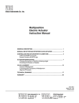
Figure 22. Inclination measurement
In this example, the device has an α angle with a horizontal position.
The y axis is not affected and the acceleration measured will remain equal to 0.
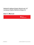
However, for the x axis, the acceleration measured will move from 0 and will be equal to
1g*sin(α).
For the z axis, the acceleration measured will be 1g*cos(α).
Figure 23. Sinus and Cosinus functions
1.50
1.00
0.50
Cosinus
0.00
0
30
60
90 120 150
180 210 240 270 300 330 360
Sinus
AM00468
36/42
Doc ID 15703 Rev 1
UM0701
7.6.2
STM32-MEMS development kit
Chip selection
Depending on the type of architecture, the user has to select either an analog or digital
MEMS device. After, depending on the precision needed, the user will choose either the
LIS344ALH or LIS3LV02DL, if small-angle detection is required. If such a level of precision
is not needed, one can use the LIS302SG or LIS302DL. If the z axis is not affected (the
device is supposed to tilt around the z axis), a 2-axis accelerometer could be used.
Example 1
In the case of the LIS3LV02DL, the resolution is 1 mg per lsb. Thus, for an acceleration
variation of 1 mg, the angle measured on the z axis will be cos–1(1–10–3) = 2.5°. For the x
axis, the angle detection will be sin–1(10–3) = 0.057°. The smallest angle variation
measurable is therefore 0.057°. This difference between the x and z axis is explained by the
behavior of the sine/cosine function.
Example 2
In the case of the LIS344ALH, the resolution is given by the formula [noise
density*rt(BW*correction factor)]. BW is the bandwidth and the correction factor is linked to
the low-pass filtering for the VOUT. The resolution is 0.625 mg. Thus, for an acceleration
variation of 0.625 mg, the angle detection on the z axis will be cos–1(1-0.625*10–3) = 2°. For
the x axis, the angle detection will be sin–1(0.625*10–3) = 0.036°.
Example 3
In the case of the LIS302DL, the resolution is 18 mg per lsb. Thus, for an acceleration
variation of 18 mg, the angle measured on the z axis will be cos–1(1-18–3) = 10.9°. For the x
axis, the angle detection will be sin–1(18–3) = 1°.
Example 4
For the LIS302SG the resolution is 2.5 mg. Thus, the smallest angle variation measurable is
0.14°.
Due to the behavior of the sine/cosine functions and the angle and precision expected, the
user will have to consider the measured acceleration on one or all axes.
Doc ID 15703 Rev 1
37/42
Bill of materials
UM0701
Appendix A
Table 31.
Bill of materials
Bill of material
Designator
Comment
Description
Footprint
CN8
BNC
BNC connector
BNC
JP1, JP2, JP3, JP4, JP5, JP6, JP7, JP8,
JP9, JP10, JP11, JP12, JP13, JP14
Header 2
Header, 2-pin
HDR1X2
JP16
Header 3
Header, 3-pin
HDR1X3
CN4
Socket 3
Socket, 3-pin
HDR1X3
JP15
Header 3 x 2
Header, 3-pin, dual row
HDR2X3
CN7
Header 10 x 2
Header, 10-pin, dual row
HDR2X10
CN1, CN2
Socket 10 x 2
Socket, 10-pin, dual row
HDR2X10
CN5, CN6
Socket 12
Socket, 12-pin
HDR1X12
CN3
Socket 15
Socket, 15-pin
HDR1X15
R1
10 kΩ
Resistor
0805
38/42
Doc ID 15703 Rev 1
UM0701
Artwork prints
Appendix B
Artwork prints
This section shows the layout of the STM32-MEMS demonstration board PCB.
Figure 24. STM32-MEMS demonstration board PCB (top and bottom layers)
Doc ID 15703 Rev 1
39/42
40/42
Doc ID 15703 Rev 1
1
2
JP9
Header 2
SDO
1
SDO_JP9
2
1
2
JP7
BNC
1
2
JP8
2
4
6
Header 3 x 2
1
3
5
JP15
Header 2
SCL
SDO_SCL_JP7_8
CN8
1
2
Header 2
SDx
SDx_JP6
JP6
Header 2
1
VOUTZ_JP3 2
Header 2
1
2
JP5
Socket 12
1
2
3
4
5
6
7
8
9
10
11
12
CN5
JP3
VOUTZ
VOUTY
VOUTX
VOUTZ
Header 2
3.3 V
3.3 V_JP5
Header 2
SDO
SDO_SCL_JP7_8
Header 2
GND
GND_JP4
JP4
JP2
GND_JP4
SCL
SDx_JP6
SCL
SDx
3.3 V_JP5
VOUTX_JP1
VOUTY
1
VOUTY_JP2 2
Header 2
VOUTX
1
VOUTX_JP1 2
JP1
Socket 10 x 2
2
4
6
8
10
12
14
16
18
20
3.3 V
VOUTX
VOUTY
VOUTZ
PD
FS
VOUTZ
VOUTY
VOUTX
2
4
6
8
10
12
14
16
18
20
Int2
Int1
SDO
SDx
SCL
CS
PD
FS
1
2
3
4
5
6
7
8
9
10
11
12
13
14
15
2
4
6
8
10
12
14
16
18
20
JP12
1
2
JP13
CN4
Socket 3
1 2 3
3.3 V
1
2
JP14
AM00445
JP16
Header 3
1 2 3
Header 2
VOUTZ_JP14
Header 2
VOUTZ
Header 2
1
2
JP11
SCL _JP12
VOUTY _JP13
PD
Int1_JP10
FS
Int2_JP11
Int2
Int2_JP11
SCL
1
SCL_JP12
2
Header 2
1
2
JP10
Socket 10 x 2
1
3
5
7
9
11
13
15
17
19
CN2
Header 2
CN3
Socket 15
VOUTY
3.3 V VOUTY_JP13
Int1
Int2
SCL
SDx
SDO
CS
Int1
Int1_JP10
SDx
VOUTX
VOUTZ_JP14
CS
3.3 V
SDx
SDO
SCL
CS
Int1
Int2
SDx
SCL
PD
FS
VOUTZ
VOUTY
VOUTX
Header 10 x 2
1
3
5
7
9
11
13
15
17
19
CN7
Socket 12
24
23
22
21
20
19
18
17
16
15
14
13
CN6
Appendix C
SDO_SCL_JP7_8
SDO_JP9
VOUTY _JP2
VOUTZ_JP3
1
3
5
7
9
11
13
15
17
19
R1
10 kΩ CN1
3.3 V
Board schematic
UM0701
Board schematic
Figure 25. Board schematic
UM0701
Revision history
Revision history
Table 32.
Document revision history
Date
Revision
01-Jul-2009
1
Changes
Initial release.
Doc ID 15703 Rev 1
41/42
UM0701
Please Read Carefully:
Information in this document is provided solely in connection with ST products. STMicroelectronics NV and its subsidiaries (“ST”) reserve the
right to make changes, corrections, modifications or improvements, to this document, and the products and services described herein at any
time, without notice.
All ST products are sold pursuant to ST’s terms and conditions of sale.
Purchasers are solely responsible for the choice, selection and use of the ST products and services described herein, and ST assumes no
liability whatsoever relating to the choice, selection or use of the ST products and services described herein.
No license, express or implied, by estoppel or otherwise, to any intellectual property rights is granted under this document. If any part of this
document refers to any third party products or services it shall not be deemed a license grant by ST for the use of such third party products
or services, or any intellectual property contained therein or considered as a warranty covering the use in any manner whatsoever of such
third party products or services or any intellectual property contained therein.
UNLESS OTHERWISE SET FORTH IN ST’S TERMS AND CONDITIONS OF SALE ST DISCLAIMS ANY EXPRESS OR IMPLIED
WARRANTY WITH RESPECT TO THE USE AND/OR SALE OF ST PRODUCTS INCLUDING WITHOUT LIMITATION IMPLIED
WARRANTIES OF MERCHANTABILITY, FITNESS FOR A PARTICULAR PURPOSE (AND THEIR EQUIVALENTS UNDER THE LAWS
OF ANY JURISDICTION), OR INFRINGEMENT OF ANY PATENT, COPYRIGHT OR OTHER INTELLECTUAL PROPERTY RIGHT.
UNLESS EXPRESSLY APPROVED IN WRITING BY AN AUTHORIZED ST REPRESENTATIVE, ST PRODUCTS ARE NOT
RECOMMENDED, AUTHORIZED OR WARRANTED FOR USE IN MILITARY, AIR CRAFT, SPACE, LIFE SAVING, OR LIFE SUSTAINING
APPLICATIONS, NOR IN PRODUCTS OR SYSTEMS WHERE FAILURE OR MALFUNCTION MAY RESULT IN PERSONAL INJURY,
DEATH, OR SEVERE PROPERTY OR ENVIRONMENTAL DAMAGE. ST PRODUCTS WHICH ARE NOT SPECIFIED AS "AUTOMOTIVE
GRADE" MAY ONLY BE USED IN AUTOMOTIVE APPLICATIONS AT USER’S OWN RISK.
Resale of ST products with provisions different from the statements and/or technical features set forth in this document shall immediately void
any warranty granted by ST for the ST product or service described herein and shall not create or extend in any manner whatsoever, any
liability of ST.
ST and the ST logo are trademarks or registered trademarks of ST in various countries.
Information in this document supersedes and replaces all information previously supplied.
The ST logo is a registered trademark of STMicroelectronics. All other names are the property of their respective owners.
© 2009 STMicroelectronics - All rights reserved
STMicroelectronics group of companies
Australia - Belgium - Brazil - Canada - China - Czech Republic - Finland - France - Germany - Hong Kong - India - Israel - Italy - Japan Malaysia - Malta - Morocco - Philippines - Singapore - Spain - Sweden - Switzerland - United Kingdom - United States of America
www.st.com
42/42
Doc ID 15703 Rev 1