1
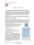
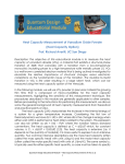
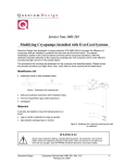
MPMS Service Note 1090-310
Testing for RSO Transport–SQUID Signal Coupling
This service note describes simple procedures for troubleshooting sources of an increase in the RSO
noise floor. It is meant as a starting point to help you rule out some basic causes of a noise floor
increase. Three types of symptoms are addressed: an otherwise good data set with numerous bad
data points that cannot be attributed to normal magnet issues (e.g., flux jumps and large SQUID
drifts); an apparent loss of reasonable SQUID tuning parameters or fluctuations in them; and a
general increase in the RSO noise floor to the region of 10-5 emu instead of the expected 10-8 emu.
The Reciprocating Sample Option (RSO) is meant to increase the ultimate sensitivity achievable with
the MPMS SQUID based magnetometer. However, with the RSO transport installed, you might
appear to get better data with the traditional DC stepped-scan technique than you do with the
synchronous RSO technique. The likely cause of this situation is coupling between the RSO transport
cable and the SQUID detection system.
Coupling and increased noise levels commonly develop after you have changed from the preferred
RSO transport to the standard transport so that you could use a specialty probe (e.g., resistivity, fiber
optic). When the RSO transport is re-installed, changes in the position of the cables can cause an
increase in coupling.
The following set of procedures will help you isolate and eliminate any such coupling. To summarize,
you will prepare the system for the procedures, perform a standard SQUID drift test, check for
coupling between the transport and SQUID voltage by manually moving the transport, and finally,
verify the quality of the cables.
I.
Prepare the System for Testing
1. Verify that the level of helium in the dewar is at least
50%. If it is not, add helium.
2. In the respective text boxes in the Magnetic Field
dialog box, set the Field to 0 (zero), set the
Approach to Oscillate, and set the mode to High
Resolution.
3. Set the temperature to a value between 101 K and
300 K and wait for it to stabilize.
4. Prepare the sample chamber and transport for
testing:
a. Remove the sample rod from the instrument.
b. Purge the sample chamber.
c.
Initialize the transport.
Quantum Design
Figure 1. Magnetic Field dialog box
MPMS Service Note 1090-310, A-0
March 15, 2004
1
Testing for RSO Transport–SQUID Signal Coupling
5. Reset the system electronics and communications by using the sequence below:
a. Exit MultiVu.
b. Turn off the power to the computer.
c.
Turn off the power to the 1822 (top left switch on MPMS XL cabinet).
d. Wait 5 seconds.
e. Return power to the system using the reverse sequence (turn on the power to the
1822, turn on the power to the computer, and start MultiVu).
6. Reset the temperature to a level near its current value (Instrument >> Temperature) and
wait until it has stabilized.
7. Perform an automatic SQUID tuning procedure.
a. Open the SQUID Tuning dialog
box shown in Figure 2
(Instrument >> SQUID Tune).
b. If necessary, select the
appropriate tab (Longitudinal or
Transverse).
c. Click in the check box for
Automatic Tuning (middle
section of the dialog).
d. Click on the Start button.
e. When the procedure ends, if the
maximum tune value is less than
0.6, please refer to the MPMS
user’s manual for more details on
SQUID-tuning procedures.
II.
Figure 2. SQUID Tuning dialog box
Perform a Standard SQUID Drift Test
Use the following procedure once the system is at zero (0) field and a stable temperature.
II.A
Set Data-Logging Parameters
1. Open the Log Data dialog (select Utilities >> Log MPMS Data).
2. Click on the Standard Items tab (Figure 3) to bring it forward.
• Click on the Select All button to log data for all the items.
• In the text box under the first column on the left, click on the dropdown arrow and
specify the appropriate voltmeter channel (Longitudinal or Transverse) to register the
SQUID voltage.
Figure 3. Standard Item tab in Log Data dialog
2
MPMS Service Note 1090-310
March 15, 2004
Quantum Design
Testing for RSO Transport–SQUID Signal Coupling
Figure 4. General tab in Log Data dialog
3. Click on the General tab to bring it forward (Figure 4).
• In the General tab, select an interval of 1.0 seconds and use the Browse button to
create a file (e.g., RSOtest.env).
• Click on the Start button to start collecting data.
• Open the plot window by clicking on the View Data button in the lower left of the
General tab.
4. After the plot window has opened, use the Graph: Data Selection dialog box (right-click
on the graph or select Graph >> Data Selection) to set the Y1 coordinate to SQUID
voltage and the X coordinate to Time, as shown in Figure 5.
5. Click on the OK button and leave the Log Data utility on for the rest of the procedures.
Figure 5. Graph: Data Selection dialog
Quantum Design
MPMS Service Note 1090-310
March 15, 2004
3
Testing for RSO Transport–SQUID Signal Coupling
II.B.
SQUID Drift Test
Perform a SQUID Drift test by using the SQUID Diagnostics dialog box shown in Figure 6
(Utilities >> Diagnostics >> SQUID).
Figure 6. Longitudinal tab of SQUID Diagnostics dialog
1. If necessary, select the appropriate tab (Longitudinal or Transverse)
2. Select the Controls: Emu Range settings:
• Click in the check box for Normal.
• Using the dropdown menu, select 0.000125 scale, then click on the Set button right
next to the text box. (Do not select the check box for Auto Reset the SQUID while
logging output).
3. Click on the Quench SQUID Coils button and wait 5 seconds.
4. Examine the plot of the environmental file: If the SQUID voltage is not within the +/– 10 V
range of the voltmeter card, perform a momentary reset by clicking on the Momentary
button in the Reset subsection.
5. If the SQUID voltage is not in the +/– 10 V range of the voltmeter card after the reset,
steadily increase the value of EMU Range until the SQUID voltage reading is in the +/– 10
V range.
You are now performing a standard SQUID drift test. If the voltage drifts out of the +/– 10 V
range during the test, perform a momentary reset as in Step 5 above. (Normally, the Auto
Reset the SQUID while logging output check box would be checked and the software
would automatically reset, but we deactivated this option for the test.)
A relatively large SQUID drift is to be expected after a recent large change in the magnetic field.
There are two ways to minimize the influence of the vortex motion in the magnet:
○
Send a heat pulse through the magnet (Utilities >> Reset Magnet) if your model of MPMS has
this option.
○
For MPMS models without the Magnet Reset capability, the solution is to leave the magnet at 0
(zero) field for a time—drift should decrease with time (up to one hour) at 0 (zero) field. Contact
Customer Service at Quantum Design if the problem has not been resolved after one hour.
If you are seeing sporadic, nonlinear changes in the SQUID voltage, consider environmental sources
that might be coupling to the SQUID, especially if your system is not shielded. To determine other
factors that can affect the noise levels, please refer to the MPMS user’s manual.
4
MPMS Service Note 1090-310
March 15, 2004
Quantum Design
Testing for RSO Transport–SQUID Signal Coupling
III.
Test for Transport–SQUID Voltage Coupling
Watch the SQUID voltage readings while you test for coupling between the SQUID voltage
and movement of the transport.
1. Open the Transport Diagnostics dialog box shown in Figure 7 (Utilities >> Diagnostics
>> Transport).
2. Move the transport by using the
Control area Move To text box:
• Enter a value of 2 in the text box
and click on the Set button.
• Enter a value of 4 in the text box
and click on the Set button.
• Enter a value of 6 in the text box
and click on the Set button.
3. Click on the Initialize button.
Under normal circumstances, you should
see no change in the SQUID voltage
when the transport is moved. But if there
Figure 7. Transport Diagnostics dialog
is significant coupling, the SQUID voltage
will register a value of either +10 V
or –10 V while the transport is moving, but it will then revert to a stable drift once the transport
has stopped moving. Any correlation between transport motion and the SQUID detection
system will limit the sensitivity that the RSO method can achieve.
If you observe a correlation, adjust the relative position and routing of the yellow Lemo RSO
transport cable with respect to all the other cables in the system. In particular, undo any cable
bundles and route the yellow Lemo through its own hole in the back of the electronics
cabinet.
After you have adjusted the cables, retest for SQUID–transport coupling by performing Steps
2 and 3 (Procedure III) until there is no discernable change in the SQUID voltage. If
performance does not improve after you have adjusted the cable placement, follow the
procedures in Section IV, "Cable Quality."
Automatic Sequence
You can use a sequence such as that shown in Figure 8 to automate the RSO transport–
SQUID coupling test. Note that this sequence will fail if there is a large SQUID drift present.
Once the sequence has been completed, examine the log file for signs of coupling.
Quantum Design
MPMS Service Note 1090-310
March 15, 2004
5
Testing for RSO Transport–SQUID Signal Coupling
Figure 8. Sequence for automatically testing for RSO transport–SQUID detector coupling.
IV.
Cable Quality
Examine the quality of the terminal connectors for all the wires involved in the SQUID
detection system. Be careful not to apply so much force that you damage the connectors
during the testing process.
1. Begin a standard SQUID drift test (Section II.B), creating a .env file with a clearly
recognizable name like Testcable.env.
2. Display the plot of SQUID voltage versus time.
3. Move the yellow triax cables that lead from the sidecar on the probe to the RF SQUID
amplifier box. The SQUID output voltage is expected to show some variation when these
cables are moved, but if the SQUID voltage records the maximum +10 V or –10 V, then
the following corrective action is required.
4. The following procedures should only be performed by a qualified Quantum Design
service representative.
a. Place the system in Standby mode (Instrument >> Standby).
b. Disconnect the grey multiplexed cable from the RF SQUID amplifier located on the
back of the probe cabinet.
c.
Disconnect the yellow triax cables.
d. Tighten by hand the connections at the end of the yellow cables.
e. Reconnect the yellow cables and then the grey multiplexed cable.
f.
Exit Standby mode by clicking on the OK button in the Standby dialog box.
g. Retest the quality of the connectors using Steps 1–3.
These cables can, in theory, be damaged by stress applied in routing. They also can be
damaged by exposure to low temperatures if the top of the probe and top of dewar get very
cold during helium transfers, especially transfers into a warm dewar.
If the above procedures do not help resolve the RSO noise floor increase, the quality of the grounding
connection inside the electronics cabinet might be at issue. Please contact Customer Service at
Quantum Design for advice before you proceed further. For service centers located inside and
outside the USA, go to the Quantum Design website (www.qdusa.com) and select Contact Us.
6
MPMS Service Note 1090-310
March 15, 2004
Quantum Design