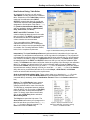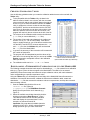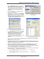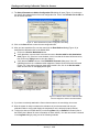
1
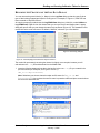
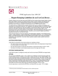
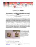
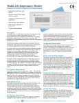
Application Note 1070-808
Reading and Creating Calibration Tables for Sensors
The Model 6000 Tables utility (TABLES32.exe) is used to read and download calibration tables to
the Model 6000 and to convert and redirect readings from external instruments. The Tables utility is
installed on the host computer of every PPMS and copies are included on the software diskettes.
Here we introduce some basic features of the Tables utility and explain how to use them. When you
become familiar with the utility you will see that it offers additional options beyond the scope of the
current application note.
Important: TABLES32.exe is to be used only with 32-bit applications. If your equipment still uses
the 16-bit PPMS application, you can obtain the 32-bit PPMS application by contacting a Customer
Service Representative at Quantum Design.
OVERVIEW OF THE TABLES UTILITY
The Tables utility lets you download calibration tables from the host computer directly into the Model
6000, edit and validate your table, assign data input and output channels, and save the table for
future use. You also can use other utilities (e.g., Log Data and GetData) in conjuction with the
Tables utility, so you can view or display the converted data and direct it to a PPMS data file. These
procedures are especially useful when you are using third-party instruments with the system, such
as additional, external thermometers.
For more information about the use of third-party instruments, refer
to Appendix A of the GPIB Commands Manual, which is part of the
PPMS User’s Manual. Also see Application Note 1070-202,
“Interfacing Third Party Instruments to the PPMS Environment,”
which is located on our website
(www.qdusa.com/resources/techdocs.html).
Figure 1. PPMS Tools desktop icon
THE TABLES DIALOGS
Start the Tables utility by double clicking on the PPMS 32-bit
Tools desktop icon (Figure 1) or on the Tables32.exe file,
which is located in the C:\QdPpms\Tools directory.
PPMS Data Channels Dialog
When Tables32.exe starts, it opens PPMS Data Channels
(Figure 2), an interactive dialog box that displays a list of
channels (Chan.), their mappings (Data Source), and whether
a calibration table is associated with the channel (Tabled?).
The channels with "-none-" for the Data Source are generally
"Available" for you to use for redirected (converted) readings.
Available channels are those numbered 20-29, 53-61, and
67-93, unless they have already been assigned (some are used
for PPMS options). All other channels are for system
functions—do not use them unless a service representative
gives you other instructions.
Quantum Design
Application Note 1070-808, Rev. B-1
January 3, 2006
Figure 2. PPMS Data Channels dialog
box
1
Reading and Creating Calibration Tables for Sensors
The Available channels that are also used for PPMS options are the following:
•
Chan 23:
MFP/Rotator
•
Chan 25:
ACMS/VSM
•
Chan 27:
Heat Capacity/He3
•
Chan 55–57:
EverCool
Note: Some of the Available channels are not supported in the Model 6000, so you cannot assign
data to them. Those are channel numbers 53–54, 67–68, and 94–99.
To begin using the Tables utility, double-click on one of the "Available" channels in the PPMS Data
Channels dialog or select a channel and click on the Redirect Data button. In the dialog shown in
Figure 2, we selected Channel 29.
When you select a channel the Data Redirect dialog will
open (Figure 3). As you can see, Channel 29 has been
automatically entered into the Destination Channel text
box. Depending on how you intend to use the Tables
utility, you can select a Source option or you can select
-none- (no data source) for special purposes.
For example, as we demonstrate in a later section, you
can set up one of the user bridge channels to measure
the resistance of an external thermometer and use the
Tables utility to convert it to temperature.
Figure 3. Data Redirect dialog box
But perhaps you want to send data such as capacitance from an external instrument to the Tables
utility. This type of situation is briefly discussed in the last section.
Data Redirect Dialog: Channel Settings
Some controls in the Data Redirect dialog box are inactive until later in the procedures. Below we
focus on the most commonly used controls, especially those used when you first start and set up the
Tables utility.
Source: This menu box displays the channels and their current data source (or mapping). Data from
the selected Source channel will be directed to the Destination Channel and converted through the
calibration table.
Destination Channel: This number refers to the channel that will read the calibration table and
display the converted data. The channel number is automatically entered into the text box when you
click on a channel in the PPMS Data Channels dialog. Note that you should only use channels 20–
29, 53–61, and 69-93—the other channels have been set aside for the system or they are not
supported.
Tables: When you click on the Edit New Table button, the program will prompt you to open a table
from the host computer. After you select and open the table, the Table Editor section will appear,
showing the calibration data (see Figure 4). The Edit Current Table button is for use when you have
loaded and saved a table for a channel and want to use that table again.
Buttons: The Map Assistant button opens the Map Assistant dialog, which is used to map Model
6000 commands (e.g., % error) to selected channels. The Cancel button closes the Data Redirect
dialog but leaves the PPMS Data Channels dialog open.
The Apply and OK buttons become active after any change is made to the settings, such as
selecting a new Source channel or turning a table on or off by checking the Tables text box (Use
the table ...). When you click on the Apply button, it saves the change and "sets" the status of the
Tabled? column for the Destination Channel to "On" or "Off". When the status is "Off," data is not
saved to the log file, preserving system space. The OK button acts the same as the Apply button but
it also closes the Data Redirect dialog.
2
Application Note 1070-808, Rev. B-1
January 3, 2006
Quantum Design
Reading and Creating Calibration Tables for Sensors
Data Redirect Dialog: Table Editor
As suggested by its name, you will use the
Table Editor to modify and save the calibration
table. Subsections of the Table Editor include a
readout of the calibration table (INPUT,
OUTPUT); controls that allow you to edit and
validate the calibration table (Interpolation) or
designate the final location of the data or *.cfg
file (Send to channel/Send to Model 6000);
and four application buttons (<<Edit Entries,
Help, Save to Disk, and Done).
INPUT and OUTPUT columns: These
columns display the data columns for the table
that you opened. The INPUT column contains
the measurement data and the OUTPUT
column contains the converted data.
To be compatible with the Tables utility,
calibration tables must have 3–79 data pairs,
and the two columns must be separated by tabs
or commas. See "Creating Calibration Tables,"
below, for the complete requirements.
Figure 4. Data Redirect dialog and Table Editor
Interpolation: The Input Data/Output Data settings determine the interpolation for the input and
output data. (For temperature measurements, use the log scales for interpolation). The program will
not extrapolate beyond the values of the table when data is being collected, but you can extrapolate
new values for the table by using the <<Edit Entries button (see below). The Graph button graphs
the data displayed in the INPUT and OUTPUT columns so that you can verify the calibration data
visually. The Validate button starts a utility that checks the regularity of the intervals in the calibration
table (e.g., perhaps you deleted entries from a large calibration table to fit into the Tables utility).
Note that the Validate utility will not let you send a *.cfg file to the Model 6000 if there are unequal
intervals between readings, although it will let you create the *.tab and *.cfg files. If the Validate
utility does not let you download the table or file, use the Graph, <<Edit Entries, and Validate
buttons to redo the table according to the requirements.
Send to channel/Send to Model 6000: These options allow you to download a *.cfg file to the
Model 6000 (click on the Send to Model 6000 button) and designate the final location of the
converted data (if necessary, enter the Destination Channel number in the Send to channel text
box).
Buttons: The <<Edit Entries button opens a
popup menu (Figure 5) with commands for
changing selected cells or rows of the data file.
To interpolate or extrapolate between readings,
select an INPUT cell, click on the << Edit Entry
button, and select an interpolate/extrapolate
option. To directly enter values into the table,
click on the << Edit Entry button and select
Manual Entry Mode.
The Help button opens the Help menu. The
Save to Disk button saves your changes to the
table file and allows you to save files (in *.cfg
or *.tab format) to the host computer. The
Done button exits the Table utility.
Quantum Design
Figure 5. Popup command menu for
editing the data table, opened by clicking
on the << Edit Entries button
Application Note 1070-808, Rev. B-1
January 3, 2006
3
Reading and Creating Calibration Tables for Sensors
CREATING CALIBRATION TABLES
Use the following guidelines when you create the calibration tables that are to be used with the
Tables utility:
•
To be compatible with the Tables utility, the data in the
table file must be listed in two columns, with the converted
values on the left and the raw (original) data on the right, as
shown in Figure 6. When the table is read into the Tables
utility, it reorders the columns so that the raw data values
are the INPUT and the converted values are the OUTPUT
(see Figure 4). Note that you can leave column titles in the
table file, and there can be more than two columns—the
program will read only the two columns at the left of the file.
•
The columns of the calibration table must be tab delimited
(*.tbl files) or comma delimited (*.cal files).
•
The number of input and output data pairs in a table must
be from 3 to 79 (i.e., 3 to 79 rows of data). If the table is
larger or smaller than that, you will be able to read the data
into the INPUT and OUTPUT columns and save the *.tab
and *.cfg files, but the Validate utility will not download
the *.cfg file to the Model 6000.
•
In general, the accuracy of the conversion will increase with
the number of data points.
•
The program will not extrapolate beyond the values of the
table when it is converting data, but you can use an <<Edit
Entries command to extrapolate values in the calibration
table (see above).
•
Figure 6. Sample tab-delimited calibration
table for a Cernox thermometer
(thermometer and table by Lakeshore)
The calibration table can be in *.txt or *.doc format.
DOWNLOADING A THERMOMETER CALIBRATION TABLE TO THE MODEL 6000
The following example shows the basic steps for downloading a *.cfg file created from a calibration
table (e.g., Figure 6) from the host computer to the Model 6000. The table is for an external
(additional) Cernox thermometer and reflects its unique calibration values, with each resistance
value corresponding to a specific temperature value.
Using the Tables utility, we will designate a user bridge in the Model 6000 that will measure the
resistance of an external thermometer; validate the thermometer calibration table; create and
download a *.cfg file that converts the resistance values to temperatures; and map the converted
data to another channel.
1. Start the Tables utility (double-click on the
TABLES32.exe file, located in
C:\QdPpms\Tools). The PPMS Data Channels
dialog box will open with a list of channels (e.g.,
Figure 7).
2. Select an Available user bridge channel by doubleclicking one that has a Data Source of "-none-."
This channel will be used to read the calibration
table and display the converted data. For this
example, we selected Channel 29.
Important: Only map data to Available channels
(channels 20-29, 53-61, 69-93), unless Quantum
Design personnel give you other instructions.
4
Figure 7. Channel 29 selected as the data source
Application Note 1070-808, Rev. B-1
January 3, 2006
Quantum Design
Reading and Creating Calibration Tables for Sensors
3. When the Data Redirect dialog opens (Figure 8),
select a Source channel. Here we selected “04Bridge 1 Resist”, which means that Bridge 1 on the
user bridge board will be used to measure the
resistance of the Cernox thermometer we have
connected.
4. Click on the Apply button to set Bridge 1 as the
data source for Channel 29.
5. The application will be reflected in the PPMS Data
Channels dialog—as shown in Figure 9, the Data
Source for Channel 29 will change from "-none-" to
“04-Bridge 1 Resist”. Note that the Tabled? column
now reads "Yes, Off" instead of "No."
Figure 8. The Redirect Data dialog with the Source
channel selected
Figure 9. The PPMS Data Channels dialog with Channel 29
set up to use Bridge 1 as the data source
6. In the Data Redirect dialog, click on the Edit New
Table button. The program will prompt you to
open the appropriate calibration table for the
external thermometer. (If you see popup
messages, such as "Unknown file format ...," when
you open the file, click on the OK button and
continue.)
Figure 10. The Data Redirect dialog and Table Editor
with a calibration table downloaded.
7. When you open the calibration table, the Tables utility will automatically read it into the Table
Editor window, as shown in Figure 10.
8. Verify that the resistance values are in the Input column and the temperature values are in the
Output column. If they are not, you must exchange the columns in the original table and open it
again (see "Creating Calibration Tables" above).
9. When the values have been read correctly, you can use the Table Editor options to validate,
graph, or change the scale of the interpolation of the table. Because we are measuring
temperature, we should use log scales for interpolation. You also can type data into the table by
selecting Manual Entry Mode in the <<Edit Entries >> popup (Figure 5).
10. After you have edited the calibration data and validated your table, save this version of the table
and the associated *.cfg file onto the host computer.
•
Click on the Save to Disk button and save the file with a *.tab extension (e.g.,
cernox1.tab).
•
Click on the Save to Disk button again, saving the file with a *.cfg extension (e.g.,
cernox1.cfg).
Quantum Design
Application Note 1070-808, Rev. B-1
January 3, 2006
5
Reading and Creating Calibration Tables for Sensors
11. The Select Parameters to Add to Configuration File dialog will open (Figure 11) so that you
can specify the characteristics of the new configuration file. Click in the Set table use to ON text
box to activate the table.
Figure 11. Select Parameters to Add to Configuration File dialog
12. Click on the Save button to save the new configuration file.
13. After you have saved the files, use the controls in the Data Redirect dialog (Figure 10) to
download the calibration table to the Model 6000:
•
Click on the Send to Model 6000 button.
•
Verify that there is now a check in the text box next to Use the table for this destination
chan (Figure 12). (If the box is not checked, click in it so that the channel will be turned on,
then click on the Apply button to save the change.)
•
Verify that the Tabled? column of the PPMS Data Channels dialog says “Yes, On”,
indicating that there is a calibration table mapped to Channel 29 and it has been activated
(Figure 13). If the column does not show that the table is On, click in the Use the table...
check box and click on the Apply button again.
Figure 12. Turning on the channel
Figure 13. Tabled? column when a calibration table
has been mapped to Channel 29 and activated
14. If you have not already attached the Cernox thermometer to the user bridge, do so now.
15. Now the system is ready to measure the resistance of your thermometer and use your
calibration table to convert and display the temperature on the selected (output) channel.
16. To direct the data to a PPMS data file, use the Log Data utility or GetData command (refer to
the PPMS User's Manual for more information on these utilities). You also can rename a channel
in the Log Data dialog by using one of the following methods.
6
Application Note 1070-808, Rev. B-1
January 3, 2006
Quantum Design
Reading and Creating Calibration Tables for Sensors
RENAMING THE CHANNELS OF THE LOG DATA DIALOG
You can rename the generic labels (i.e., Map xx) in the Log Data dialog so that they specify what
type of data is being mapped and where it is being sent. For example, in Figure 14, “MAP 29” has
been renamed to “MyCernoxTherm.”
An easy but temporary method uses the Log PPMS Data dialog box (in MultiVu, select Utilities >>
Log PPMS Data). Right-click on the channel that you set up to receive and display data. A popup
dialog will open so that you can change the name for that channel (Figure 15). The drawback to this
method is that the name will revert to its default, “MAP 29,” whenever you close MultiVu.
Figure 15. Renaming "Map 29"
Figure 14. Channel (Map) 29 renamed as “MyCernoxTherm”
The method for permanently renaming the channel is slightly more complex, because you will
edit and save the *.cfg file and download it to the Model 6000.
1. Insert the following statement just above the last line in the new *.cfg file you created in the
previous section (for examples, see Figures 16 and 17):
MAP_ID 29 “MyCernoxTherm”;
Note: Substitute your chosen channel number and file name for "Map_ID 29" and
"MyCernoxTherm". Also, enclose the new file name in quotation marks and place a semicolon at
the end of the statement line.
Figure 16. *.cfg file before making any modifications
Figure 17. *.cfg file modified to rename Channel 29
Quantum Design
Application Note 1070-808, Rev. B-1
January 3, 2006
7
Reading and Creating Calibration Tables for Sensors
2. After you have made your changes, save the *.cfg file to the QdPpms directory on the host
computer.
Next, you will use the PPMS Rom Config 32 dialog to download the edited *.cfg file from the host
computer to the Model 6000.
3. Open the PPMS Rom Config 32 dialog (Figure 18) by clicking on Romcfg32.exe, located in
C:\QdPpms\Tools.
Figure 18. PPMS Rom Config 32 dialog box
4. On the toolbar of the PPMS Rom Config 32 dialog (Figure 19), select Send to PPMS >>
Send Config.
Figure 19. Send to PPMS dropdown menu
5. A dialog box will open so that you can select the file to download. Select the *.cfg file you
edited.
6. The *.cfg file will be downloaded to the Model 6000 and the name for Channel 29 will be
changed to “MyCernoxTherm."
USING THE TABLES UTILITY WITH EXTERNAL MEASUREMENT DEVICES
Source Channels for External Measurement Devices
You can easily use the Tables utility with an external measurement device by adapting the earlier
instructions. For the adaptation, you will use an alternate type of Source channel to send the data to
the Destination Channels.
1. Follow Steps 1 and 2 in the instructions for
downloading a calibration table.
2. In Step 3, select a channel such as
"12-Analog Sig. Input 1" instead of a user
bridge channel (Figure 20).
3. Follow the remaining instructions as if you
were using a user bridge channel to read
the measurements.
Figure 20. Alternate Source channels for sending external
measurements to the Model 6000
Special Situations
If you would like to explore using the Tables utility for special purposes, such as converting and
displaying measurement data without sending it through a Source channel (i.e., Source channel will
be -none-), or have any other questions, please contact Customer Service at Quantum Design.
8
Application Note 1070-808, Rev. B-1
January 3, 2006
Quantum Design