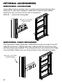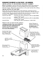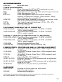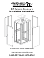
1
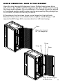
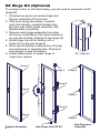
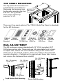
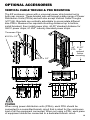
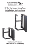
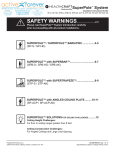
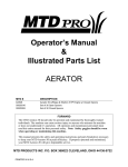
EZ Seismic Enclosure
Installation Instructions
GL840EZ-3042 (Custom sizes available)
WeRackYourWorld.com
1-866-TRY-GLCC (879-4522)
Preface
This manual is provided to prevent service personnel from committing
an act that results in the risk of fire, electric shock, or injury to persons.
Only trained service personnel should receive, unpack, and assemble
the EZ Enclosure. In addition, only trained service personnel should
install equipment in enclosures.
Safety Symbols Used in this Manual
This manual provides general safety guidelines to be observed during
installation, operation, and maintenance of the EZ Enclosure.
WARNING: Failure to follow directions in the warning could result in
injury to persons or loss of life.
CAUTION: Failure to follow directions in the caution could result in
damage to equipment or storage data.
Safety Considerations
WARNING: Improper handling and use of the EZ Enclosure could result
in equipment damage, serious injury, or possible death.
Only trained service personnel should be used to remove the enclosure
from the pallet. Also, be sure you have a sufficient number of service
personnel. Do not attempt to move enclosures by yourself.
Only UL® Listed ITE (Information Technology Equipment) units should
be installed inside the EZ Enclosure.
Be sure to read and follow all individual manufacturer equipment
manuals for safety and installation instructions.
Proper spacing is required when installing electrical equipment to avoid
electrical shock. Maintain minimum spacing between the accessories
and components and the computer enclosure assembly for safe
operation of the equipment when installed in accordance with the
National Electric Code ANSI/NFPA 70-1999.
The ambient temperature operating range for the EZ Enclosure and
accessories is +50 to +95° F (+10 to +35° C).
The non-operating temperature is -4 to +140° F (-20 to +60° C).
2
Service
The EZ Enclosure should be repaired by personnel trained by Great
Lakes, or returned to Great Lakes for repair or replacement. Contact
Great Lakes Technical Support at 814.734.7303 or at werackyourworld.
com
What’s Included
• EZ unit (assembled)
• Keys
• (50) M6 cage nuts (3/8" square)
• This user’s manual
• Seismic Anchor Kit with Installation Instructions
This user’s manual applies to the following Great Lakes
enclosure:
Part No.H
GL840EZ-304284
WDRMU
30
42
45*
EZ weight capacity: 1000 lbs.
EZ Non-Seismic Weight capacity: 3000 lbs.
* Other sizes available upon request
Installation
Receiving, Unpacking, and Removing the EZ Enclosure from
the Pallet
Inspect and report any damage before receiving. Unpack the enclosure
by carefully removing the corrugated carton and corners. Avoid
damaging the enclosure when removing packaging.
WARNING: Only trained service personnel should be used to remove
the enclosure from the pallet. Also, be sure you have a sufficient
number of service personnel. Do not attempt to move enclosures
by yourself.
WARNING: Be careful when moving enclosures before installation.
Sudden stops and starts, excessive force, obstructed routes, and
uneven floor surfaces may cause the enclosure to topple over.
3
Loading Equipment
WARNING: Only install equipment after the EZ Enclosure has been
properly secured. Do not move the EZ Enclosure assembly while
loaded.
Rated or maximum load capacity for the EZ Enclosure is 1000 lbs.
(3000 lb. non-seismic weight capacity). Enclosure must be secured to
floor using the included AK101 Seismic Anchor Bolts.
To maintain a uniform distribution of the mechanical load in the EZ
Enclosure, load the heaviest equipment first, at the bottom of the
EZ Enclosure and load the lighter units at the top.
OPERATING DOOR HANDLE
The door swing handles have been installed at the manufacturer.
No additional assembly is required. The EZ doors have a three point
latching system. To operate the swing handle, lift up at the bottom of
the handle then swing the handle to the right to open. The handle must
be kept in this position to close the door. Return the handle to the initial
position and use the key provided to lock the handle.
Important note: Doors are reversible, but require
an additional hinge kit. Please contact your
distributor/Great Lakes representative for the
EZ Hinge Kit.
4
DOOR REMOVAL AND ATTACHMENT
Open the door beyond 90 degrees. Use a Phillips head screw driver
and remove the middle captive hinge from the door. (Make sure to keep
the hinge and hardware for re-installation) The handle should be placed
in the closed position and the door can be removed by lifting straight up.
To re-install, reverse the above procedure.
EZ enclosure front and rear doors come hinged on the right side.
Because these doors are installed with a captive middle hinge, it will
require the EZ Hinge Kit to reverse door to a left hand swing.
Door
Open door beyond
90o; lift straight up
Hinge
Hinge Pin
Door
Align all three hinges
to attach door
5
EZ Hinge Kit (Optional)
To reverse a door to left hand swing, you will need to purchase an EZ
Hinge Kit.
1. Uninstall top portion of center hinge and lift door assembly off enclosure.
2. With door laying face down, uninstall
rods from handle; uninstall handle from
the door and rotate entire assembly 180.
Reassemble completely.
3. Remove each hinge assembly from door
and move (orientated in the same direction)
up one set of holes; dispose of top hinge (A).
4. Install hinge from kit to bottom set of
holes; this is the new hinge B.
5. Move top and bottom male portion of hinge
(on enclosure) to opposite side. Drop door
onto hinges in new orientation.
EZ Hinge Kit
6. Install male portion in center hinge to
make door captive.
Hinge A
Hinge A
Hinge B
Hinge B
Hinge B
Hinge A
Hinge A
Hinge A
Hinge B
Original Assembly
6
New Hinge from EZ Kit
New Reversed
Assembly
SIDE PANEL REMOVAL
Side panels are secured from inside
the enclosure.
#10-32
Tinnerman
Clips
Caution: removal of side panels
requires at least two people, one to
unscrew and one to hold the side
panel once loosened.
#10-32 x 3/8"
Seismic Anchor Kit
The EZ seismic enclosure will need to be secured to the floor with
the included AK101 seismic anchoring bolts. Please see the AK101
instructions (included in the orange bag) for additional details. Each
enclosure comes with 4 seismic washer plates. These will have to be
placed before securing the AK101 bolts.
Seismic
Anchor
Washer
Plate
F
F
7
TOP PANEL MOUNTING
The top panel of the enclosure is
installed at the manufacturer.
Removing the top panel can #10-32 x 1/2"
Pan Head
be done by removing the four Screws
#10-32 x 1/2" lg screws.
Then simply lift the top
panel out or off.
There are 6 top panel options (The TPES-S Solid Top Panel is standard)
for the EZ Enclsoure:
TPES-STPES-PTPES-FTPES-F10TPES-2F10TPES-B
Solid PerforatedThree, One, 10" 550Two, 10" 550 Grommet
Standard
75 CFM Fans CFM Fan
CFM FansBrush
RAIL ADJUSTMENT
The EZ enclosure comes standard with 19" 310-E compliant, 3/8"
SQ hole mounting rails. These rails are fully adjustable front to back.
To adjust rails, loosen the ¼-20 hardware using a 3/8" socket and
slide them to the desired position. (There are "tabs" in the horizontal
mounting brackets – if adjustment is required past these tabs, loosen
and remove the hardware then reinstall)
A
1/4 - 20 Locking
Flange Nut
1/4 - 20 Hex
Head Bolt
1/4 - 20 Sliding
Nut Plate
A
B
A
B
1/4 - 20
Carrige Bolt
Top & Bottom Rail Mounting
8
B
Center Rail Mounting
OPTIONAL ACCESSORIES
VERTICAL CABLE TROUGH & PDU MOUNTING
The EZ enclosure comes with a universal power strip bracket set in
both rear corners. These bracket sets will accept a wide range of Power
Distribution Units (PDUs) and will also accept Vertical Cable Troughs
(VCT-84). Brackets are vertically adjustable to accomodate different
size PDUs. Measure the required mounting distance top to bottom,
install brackest, then install power strip. 44.00" standard distance for
GLCC power strips; 61.250" industry standard power strips.
4
3
2
1
8
7
6
5
4
D
Tinnerman Clips
D
#10-32 x 1/2"
C
C
B
1.12
2.74
2.74
7.56
3.86
2.74
44" 61.25"
.95
for
STD
optional
button
.95
mounting
B
#10-32 x 1/4"
B
2.43
3.00
1.64
1.64
A
A
8
4
1.12
3
2.74
2.74
2
.95
1
7
6
3.00
7.56
3.86
.95
2.74
2.43
3.00
1.12
2.74
2.19
1.64
1.64
6.19
5
3.00
1.37
2.74
2.19
7.56
4
.95
1.64
Power
When using power
distribution
units (PDUs), each PDU should be
3.00
3.00
1.37
6.19
connected to a committed
branch circuit that is rated for the continuous
load of all
the equipment
connected.
When not using a PDU, each piece
1.12
2.74
2.74
.95
of equipment should be connected to a dedicated branch circuit.
9
OPTIONAL ACCESSORIES
Horizontal Lacing BaRs
Lacing Bars feature double rows of vertical and horizontal slots that
allow you to use velcro straps or cable ties to secure your cables,
which you can run from front to rear of enclosure.
HLB-36 Horizontal Lacing Bar
#10-32 x 1/2" Pan
Head Screws
B
Horizontal Cable organizer
The Horizontal Cable Organizer (HCM-D36) can be mounted in the 30"
wide EZ enclosure. If these parts are ordered with the enclosure, they
will have been pre-installed. The side panel has to be removed for these
to be installed. Make sure you have access to the side panel screws.
#10-32 x 1/2" Pan
Head Screws
10
OPTIONAL ACCESSORIES
OVERHEAD CABLE TROUGH
#10-32 x 1/2" Pan
Head Screws
When ordered with the enclosure,
the overhead cable trough ships
assembled, but not installed. The
top of the EZ enclosure has a variety
of mounting holes. Place the trough
where you require cable routing.
ZERO RMU MOUNTING, ZR1 & ZR2
Both ZR bracket kits (ZR1 and ZR2) fit on the EZ enclosure. These
allow for "0" RMU mounting of 19" rack mount power strip units or other
1 or 2 RMU equipment (such as patch panels). Install the bracket onto
the rail or post toward the side panel. It is important to ensure you have
18.31" between the inner holes for 19" mounting.
2 RMU
18.31"
18.31"
1 RMU
11
Exhaust Chimney & Fan tray - ES SERIES
INSTALLATION OF ADJUSTABLE EXHAUST CHIMNEY
Before installation, remove the rear, top knockout from the enclosure.
Place assembled chimney on top and attach from the inside using
#10-32 screws. Raise the outer section so the seal touches the ceiling.
INSTALLATION OF FAN TRAY
Place fan tray onto fixed portion of the chimney, ensuring cord is
hanging through the chimney and into the enclosure. The fan will rest
on four studs. Secure the fan with #10-32 nuts from the inside of the
enclosure. Available Chimney and Fan Trays include:
GL-EC-42-1832
GL-EC-42-3246
GL-ECFT42
Chimney for 42"D enclosure with an adjustable range of 18" to 32"
Chimney for 42"D enclosure with an adjustable range of 32" to 46"
Fan Tray for 42"D enclosure, 1200 CFM
Please note: In order for the exhaust
chimney and fan tray to be effective,
a solid rear door must be used.
Please call your distributor/
Great Lakes representative
for more information.
Cord for Fan Tray to
Exit back Through
the Chimney and
Rear of Enclosure
Adjust Chimney to
Desired Height; Use
Screwdriver to Punch
Out Appropriate
Knockout for Knob
(Qty. 2 - Both Sides)
Drop Fan Tray Into
Fixed Bottom Portion
of Chimney - Notches
Should Fall Onto Studs
in Chimney
#10-32 x 1/2"L
Mounting Screws
(Qty. 4)
Mounting Holes
For #10-32
Screws (Qty. 4)
Install Nuts Onto
Studs from Bottom
Inside Enclosure
(Qty. 4)
Use Screwdriver
to Punch Out
Rear Knockout
12
NETWORKING/ GANGING
Enclosures can be networked using
the G101ES
Lock Washer
Washer
Wing
Nut
Washer
Thumb
Screws
No Tools Required!
GROUNDING
GROUNDING KIT, GR101
Grounding studs in our EZ Enclosure provide
a point to which the doors may be grounded to the
enclosure and from which the enclosure may be
connected to the facility’s common ground.
Using the grounding straps supplied, connect one
end of the strap to copper ground stud on the side panels
and/or doors and the other end to copper ground
stud on the frame of the enclosure. Once all
straps have been connected to a copper frame
Ground Stud:
stud, have at least one frame stud connected to
#10-32 x 1 7/8 LG
or M6 x 50mm LG
the common building ground.
COPPER BUS BARS, CBB-72
It is important to note that grounding the enclosure
does not ground the equipment mounted within it.
In order for any individual devices and
components mounted within an enclosure
to be grounded, they must be
connected to a copper
bus bar.
#10-32 Nut
Insulator
#10-32 Nut
13
Protective Grounding
Protective grounding studs are provided along with grounding jumper
wires that electrically bond the enclosure doors to the
enclosure frame.
WARNING: To avoid injury to persons or loss of life, ground each
enclosure individually to the dedicated branch circuit ground.
Connecting Main Protective Grounding Stud to the
Dedicated Branch Circuit Ground
Connect the dedicated branch circuit ground connector to the main
protective grounding stud located inside at the bottom rear
of the enclosure frame using a listed ring or closed-loop terminal.
Connecting Main Protective Grounding Stud to the
Protective Bonding Conductors
Connect the rear doors to the main protective grounding studs located
inside at the bottom and top rear of the enclosure chassis
using a listed ring or closed-loop terminal. Connect the front door to the
grounding stud located inside at the bottom front of the
enclosure frame using a listed ring or closed-loop terminal.
Parts Not Bonded to Protective Earthing Terminal
The following parts are not effectively bonded to the protective earthing
terminal: rails and front to back rail horizontals. If these parts need to
be bonded to the protective earthing terminal, do so in accordance with
Article 250 of the National Electric Code.
14
ACCESSORIES
PART NO.DESCRIPTION
CABLE MANAGEMENT
BGS-84-48
Brush Grommet for 84"H x 42"D enclosure; to cover rear vertical cable pass through
BGT
Brush Grommet to cover top cable pass through knockouts
CMP
Cable Management Post, 3"
ESC-K12
Cable Management Rail Kit for front or rear rails;
includes 12 sections of "fingers" (each section 7 RMU);
rails will need to be recessed 4.5"
HCM-D36
Horizontal Cable Organizer; to mount from the front to the rear of the enclosure includes hardware
TCT30
Top Cable Trough and hardware; 6.5"W x 4"D x 30"L
VCT-84
Vertical Cable Trough
VCT-84C
Cover for VCT-84
STATIONARY SHELVES FOR 19" MOUNTING
7206-FR-ADHD
Front/Rear Mount adjustable, 17.50"W x 27.25"D,
150 lb. weight capacity
7206-FR-A32HD Front/Rear Mount adjustable, 17.50"W x 32.00"D,
300 lb. weight capacity
SLIDING & SPECIALTY SHELVES FOR 19" MOUNTING
7206-FRSL-ADHD Front/Rear Mount adjustable, 17.50"W x 26.00"D,
100 lb. weight capacity
7206-FRSLA300 Front/Rear Mount adjustable, 14.33"W x 30.00"D,
300 lb. weight capacity
7206-MKM
Monitor/Keyboard/Mouse Shelf
7206-PKB-MT
Pivoting Keyboard Tray with Mouse Tray
POWER STRIPS, COPPER BUS BAR, & COOLING EQUIPMENT
7215-20ARTLP
16 position, 20 amp Power Strip; 5-20R receptacle and
L5-20P plug
7215-20AR
16 position, 20 amp Power Strip; 5-20R receptacle and 5-20P plug
7215-30A
24 position, 30 amp Power Strip; 5-20R receptacle and
L5-30P plug
CBB-72
Copper Bus Bar 70" (isolated)
GL-EC-42-1832
Exhaust Chimney for 42"D enclosure with an adjustable range of 18" to 32"
GL-EC-42-3246
Exhaust Chimney for 42"D enclosure with an adjustable range of 32" to 46"
GL-ECFT42
Optional Fan Tray for chimney, 1200 CFM
HARDWARE
HDW-105-50
G101ES
Package of 50 M6 cage nuts with screws
(12mm screw length)
Networking/Ganging Kit
Visit our web site at www.werackyourworld.com for a complete list of available accessories.
NOT RESPONSIBLE FOR TYPOGRAPHICAL ERRORS
15
Thank you
for your
business!
ISO 9000 : 2008
ISO 9001 : 2008 Registered
ETSI Associate Member
FORM: #MS-5.02-25, REV 1