1
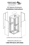
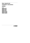
19" EIA Wall Mount Swing Rack
Installation Instructions
(UL60950-1/UL2416 SR Series Equipment Rack)
WeRackYourWorld.com
1-866-TRY-GLCC (879-4522)
PREFACE
MAXIMUM LOAD CAPACITY: 50 lb. capacity for every size of SR Swing Rack
SAFETY SYMBOLS USED IN THIS MANUAL
This manual provides general safety guidelines to be observed during
installation, operation, and maintenance of the SR Swing Rack.
SERVICE
The SR Swing Rack should be repaired by personnel trained by Great Lakes,
or returned to Great Lakes for repair or replacement. Contact Great Lakes
Technical Support at 814.734.7303 or at werackyourworld.com
This manual is provided to prevent service personnel from committing an act that
results in the risk of fire, electric shock, or injury. Only trained service personnel
should receive, unpack, and assemble the SR Swing Rack. In addition, only
trained service personnel should install equipment in the swing rack.
To maintain uniform distribution of the mechanical load in the SR Swing Rack,
load the heaviest equipment first, at the bottom of the SR Swing Rack and load
the lighter units at the top.
WHAT’S INCLUDED
WARNING: Failure to follow directions in the warning could result in injury to
persons or loss of life.
SR Swing rack with grounding kit
50 X 12-24 x ½" Phillips pan head screws
This user’s manual
MOUNTING INSTRUCTIONS
CAUTION: Failure to follow directions in the caution could result in damage to
equipment or storage data.
SAFETY CONSIDERATIONS
WARNING: Improper handling and use of the SR Swing Rack could result in
equipment damage, serious injury, or possible death.
Only UL® Listed ITE (Information Technology Equipment) units should be
installed inside the SR Swing Rack.
Be sure to read and follow all individual manufacturer equipment manuals for
safety and installation instructions.
Proper spacing is required when installing electrical equipment to avoid
electrical shock.
Maintain minimum spacing between the accessories and components and
the computer enclosure assembly for safe operation of the equipment when
installed in accordance with the National Electric Code ANSI/NFPA 70-1999.
The ambient temperature operating range for the SR Swing Rack and
accessories is +50 to +95°F (+10 to +35°C).
The non-operating temperature is -4 to +140°F (-20 to +60°C)
Wood Studded Wall
Once the location on the wall has been determined, inspect the wall surface.
The wall must be flat and square in the horizontal and vertical plane to ensure
the SR Swing Rack closes correctly. If the wall is not flat and square, you might
be required to use shims.
Wood studded wall mounting instructions apply to a 2" x 4" wood stud wall with
3/4" plywood.
Recommended Mounting Hardware for Wood Studded Wall
Qty (4) 3/8 x 2" long Lag Bolts and 1" O.D. Flat Washer
Masonry Wall Surface
For masonry wall surface, the installer must provide all the appropriate
hardware.
PROTECTIVE GROUNDING
Protective grounding lugs are provided along with grounding jumper wires that
electrically bond the swing frame to the rest of the SR Swing Rack.
WARNING: To avoid injury to persons or loss of life, ground each SR Swing
Rack individually to the dedicated branch circuit ground.
Loading Equipment
Connecting Main Protective Grounding Stud to the Dedicated Branch
Circuit Ground- Connect the dedicated branch circuit ground connector to the
main protective grounding lug location inside the bottom front of the side brace
using a listed ring or closed loop terminal.
WARNING: Only install equipment after the SR Swing Rack has been properly
secured. Do not move the SR Swing Rack assembly while loaded.
Connecting Main Protective Grounding Stud to the Protective Bonding
Conductors- Connect the swing frame to the main protective grounding lug
located inside at the bottom of the side brace using a listed ring or closedloop terminal and 1/4-20 x 5/8 phillips pan head screw with external tooth lock
washer and two, 1/4-20 keps nuts with external tooth washer.
INSTALLATION
2
3
19" EIA
Wall Mount Swing Rack
24SR, 36SR & 48SR
PARTS LIST
COMPONENT
TOP AND BOTTOM BRACE
SWING FRAME ASSEMBLY
SIDE BRACE ASSEMBLY REAR BRACE PANEL
#10-32 ACORN NUT
#10-32 X 1/4" PHIL PAN HD SCREWS, TYPE 23, BLACK 1/4-20 X 3/4"L FLAT HEAD SCREW W/ NYLON LOCKING PELLET
BLACK NYLON SPACER (0.50 OD, 0.26 ID 0.187 TH)
EQUIPMENT MTG. HARDWARE: #12-24 X 1/2” PHIL PAN HD SCREWS, TYPE 23 GENERAL INFORMATION
PART NO.
H
GL24SR
24.512"
GL36SR
36.763"
GL48SR
48.763"
W
20.562"
20.562"
20.562"
D
18.00"
18.00"
18.00"
GROUNDING KIT
2 BARREL GROUND LUG
1/4-20 X 5/8" PHILLIPS HEAD SCREW WITH EXTERNAL TOOTH WASHER
1/4-20 KEPS NUT WITH EXTERNAL TOOTH LOCK WASHER
JUMPER WIRE
RMU
12
19
26
The 24SR and 36SR frames are made of 14 Ga. steel. The 48SR frame
is made of 12 Ga. steel. All frames are 4"D with mounting front and rear.
Certifications: UL Listed 2416 and UL 60950-1
Construction: Steel
Finish: Black Textured Powder Coat
Grounding: Studs on side brace and swing frame with bonding lead
Rail Type: Tapped #12-24 mounting holes, front and rear
1
2
3
1
INSTRUCTION MANUAL1
TOOLS REQUIRED: 3/8" NUT DRIVER, PHILLIPS HEAD SCREWDRIVER
Special Note: Item #7 used to mount equipment to swing rack.
STEP 1
Place the back brace onto the four threaded studs on the two side brace
assemblies. Secure with four #10-32 acorn nuts. Tighten with 3/8" nut driver.
Install the top brace to the outside of the two side brace assemblies with four
#10-32 x 1/4" Phillips Pan Head screws, but do not tighten screws; install the
bottom brace in the same manner. The large formed edge of the top/bottom
braces mount towards the rear and the inside of the swing rack.
#10-32 x 1/4" Phil
Pan Head Screw
(4 locations on top)
Top/Bottom Brace
(qty. 2)
When installing a Great Lakes Swing Rack or Wall Mount to materials such as
wood, cinder block, concrete, etc., please consider the load capacity within the
swing rack or wall mount structure, and be certain to check with local authorities to
determine the appropriate hardware requirements for these conditions. Because
wall compositions may vary at different installation sites, Great Lakes cannot
warrant the fitness or suitability of any installation instructions or installation
hardware it may provide for swing rack or wall mount enclosures. Great Lakes
hereby DISCLAIMS ALL WARRANTIES, EXPRESS AND IMPLIED, INCLUDING THE
IMPLIED WARRANTIES OF MERCHANTABILITY AND FITNESS FOR A PARTICULAR
PURPOSE, REGARDING THE SUFFICIENCY, FITNESS OR SUITABILITY OF ANY
INSTALLATION INSTRUCTIONS OR INSTALLATION HARDWARE GREAT LAKES
MAY PROVIDE FOR SWING RACKS AND WALL-MOUNTED ENCLOSURES. Great
Lakes recommends that an experienced maintenance and/or technical person
be consulted regarding the proper wall-mounting hardware and procedures to be
used for the anticipated load capacity of the swing rack or wall mounted enclosure.
Side Brace
Assembly
(qty. 2)
#10-32
Acorn nut
(4 locations)
Back Brace
(qty. 1)
#10-32 x 1/4" Phil
Pan Head Screw
(4 locations on bottom)
Product specifications are subject to change without prior notice.
4
QTY.
2
1
2
1
4
8
2
2
50
Top/Bottom
Brace
5
STEP 2
UNIVERSAL
Mount the rear assembly to the wall with four lag screws (not provided).
Mounting locations are as shown.
8
Install the 19" EIA Swing Frame by retracting both pins. The pins can be locked
out for ease of assembly by retracting the outside pin into the slot provided.
The retractable pins are to be near the front of the Swing Frame when
installing.
Release the lower pin then, align the top pin to the top receptacle and release
pin. Place 1/4-20 Screw through the hole in bottom (opposite pin hinge).
Assemble spacer on exposed threads on inside of swing rack and close
Swing Frame. Tighten screw by screwing into pem nut in Swing Frame.
Repeat screw/spacer assembly for top. Finally, tighten 8 screws on the top
and bottom braces.
8
7
6
5
Install ground lug and jumper
wire as shown in
Detail A and B.
D
1/4-20 x 5/8"
Phil Pan Head
Screw
4
3
2
Mounting
Location;
2 on top,
2 on bottom
B
Ground
Lug
A
7
6
5
4
LEFT HAND SWING
3
OR
2
1
C
3
2
1
D
B
B
1/4-20 Nylon
Locking Pellet
CAUTION:
A
8
1
LEFT HAND
When installing
19" EIA equipment, make sure both retractable
(2) are
RIGHTpins
HAND
secured into the rear section that has been mounted to the wall. Be sure
all screws, nuts, and mounting hardware are tightened before loading with
equipment.
DETAIL A
SCALE 1.5
7
6
Ground
Wire
A
C
5
4
3
2
1
D
B
8
7
6
5
4
8
7
6
5
4
D
4
Receptacles for Pivot
Pins: 1 in top, 1 in bottom
3
B
1/4-20 keps nut
2
B
1
C
A
DETAIL A
Earthing
Symbol
8
7
D
DETAIL A
SCALE5 1.5
6
Retractable Pivot
Pins; 1 on top,
1 on bottom
4
3
A
DETAIL B
SCALE 0.90 : 1
2
C
1
Ground Lug
DETAIL B
B
B
C
1/4-20 bolt
DETAIL A
SCALE 1.5
Part No.
Height
GL24SR
18" on center
GL36SR
30" on center
GL48SR
6
42" on center
1/4-20 keps nut
B
B
Jumper Wire
1/4-20 keps nut
A
DETAIL B
SCALE 0.90 : 1
D
RIGHT HAND SWING
C
1/4-20 x 3/4" Flat
Head Screw
C
5
4
D
The 19" EIA Swing Frame Rack can be hinged (retractable pin) on either side.
Customer needs to determine which side is to open. To open, simply retract
both pins (top and bottom) and then open the Swing Frame Rack similar to that
of a door.
A
Secure retractable pins into receptacle (2 locations)
7
Thank you
for your
business!
ETSI Associate Member
FORM: #MS - 5.02-12, REV 7