1
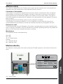
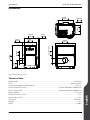
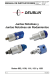
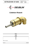
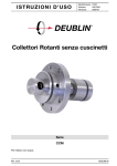
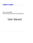
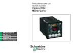
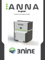
600
anna
English
Translation of the original instructions
English
User manual
Anna 600 Oil Mist Separator
Confirmation of compliance in accordance with Appendix 2:1 A
3nine AB (556572-4167), Box 1163, 131 27 Nacka Strand, declares that
Oil Mist Separator Anna 600
has been manufactured in accordance with the following directive:
•
2004/108/EG EMC Directive Electromagnetic Compatibility (EMC-directive)
•
2006/95/EG/EC Low Voltage Directive (LVD)
•
2006/42/EC Machine Directive
has been manufactured in accordance with the following harmonised standards, or parts therefore:
•
EN ISO 12100
•
EN ISO 60204-1
•
ISO 14120
Nacka Strand, 7.1. 2013 Oskar Olai CEO, Legal Officer
3nine AB, Box 1163, 131 27 Nacka Strand, Sweden
Dr Claes Inge
Technical Documentation Officer
About this manual
This document contains information which belongs to 3nine AB. No part of this publication may be
copied, stored in information recovery systems, or transmitted in any form or in any manner,
electronically or mechanically, including photocopying and recording, without the prior permission
of 3nine AB.
Title: User Manual Anna 600
Language: English
Version: Version 1 (2013-01)
English
This manual is published by 3nine AB with no guarantees. Improvements and amendments to this
manual due to typographical errors, mistakes or modifications to machines or equipment may be
made by 3nine AB at any time and without prior notice. However, such changes will be implemented in the next version of this manual.
All dimensions stated are in millimetres unless specified otherwise.
All rights reserved
©3nine AB, 2013
Publication number: 800-044-EN
Printed in Sweden
3nine AB
English 5
User manual
Anna 600 Oil Mist Separator
Health and safety rules
This manual contains instructions intended for users’ daily work with the equipment.
This manual must always be available to the individual or individuals working with the equipment.
It is important to ensure that:
•
The manual and other applicable documents are retained for the entire service life of the equipment.
•
The manual and other applicable documents are included as part of the equipment.
•
This manual is passed on to other users of the equipment.
•
This manual is updated if any supplements or amendments to the equipment take place.
•
This manual describes the methods applied when using the equipment.
Safety code
•
•
•
•
•
•
•
•
•
•
•
•
•
Before you start using the equipment and carrying out maintenance or servicing on this equipment,
please read through the applicable parts of the instruction.
Observe all Danger, Warning and Note symbols shown in the manual. Serious damage to machinery
and injury to persons may result from failing to observe this information.
Assume all electrical equipment is live.
Assume all hoses and pipelines are pressurised.
When servicing and maintaining the equipment/machine, ensure that the electrical supply and the
pressurised pipes are cut off and that the fuses are tripped. The machine must be pressure free and
the electric plug must be disconnected. Wait at least five minutes and check that rotating parts have
completely stopped.
Servicing and maintenance must be carried out by authorised service and maintenance staff only.
Follow the instructions regarding max. load, pressure and operating temperature: see the decal on the
equipment and technical data in the manual.
Use only spare parts approved by 3nine – if you are uncertain, contact 3nine technical support.
Make sure that the machine is securely mounted and installed in accordance with instructions before
starting it.
Regularly check the machine’s screws and other attachment devices.
Use the machine only for the intended use.
In the event of abnormal vibration or noise – stop the machine and consult the manual.
Electrical installation must be carried out by an authorised electrician only.
Warning devices
Warning devices and protective devices must be checked annually.
Warning texts
Danger, Warning and Note texts have the following meanings in this manual (see the illustrations below).
NOTE!
Note – Important information concerning operation, function, care or maintenance of the oil mist separator
English
WARNING!
Warning – Important information to prevent damage to the machine or impaired
oil mist separator function.
!
6 English
DANGER!
Danger – Indicates a risk of serious injury
3nine AB
User manual
Anna 600 Oil Mist Separator
Machine safety
The machine is labeled with the CE label, which means that the machine and its associated documentation meet the requirements of the Machine Directive, Annex V.
Conversion of the machine
If the machine is converted or supplemented with parts that the manufacturer does not approve,
this declaration of conformity will not apply to the parts which alter the function of the machine.
Warning decals and the identification plate on the machine must be clearly visible. If any part of
the machine bearing a warning decal is replaced, new warning decals must be applied in the same
place as before.
Damaged decals and identification plates must be replaced immediately.
If the machine is converted or added to, it is very important to ensure that this instruction is
completed/adjusted immediately to include the necessary illustrations, photographs and texts.
Demands on staff
To prevent personal injury and damage to the machine, operating staff must receive special instructions or training in accordance with the manufacturer’s manual. Operating staff may only handle the
parts for which they have received instructions or training.
Manufacturer
This machine has been manufactured by:
3nine AB
Box 1163
131 27 Nacka Strand
Sweden
Tel.: +46 8 601 35 40
Fax: +46 8 601 35 41
Machine identity
The Machine’s identity plate with serial number and CE label is placed on the inside of the service
hatch.
s epara tion tec hnology
Serie
Serial
ANNA 600
Serienummer
Serial Number
ANNA600-142-GQ0001
Tillverkningsår
Year of manufacturing
Herstellungsjahr
2013
Vikt (utan filter)
Weight (w/o filter)
Gewicht (ohne Filter)
77kg
English
Tillverkare / Manufacturer / Hersteller
3Nine AB, Box 1163
131 27 Nacka strand, Sweden, +46(0)8 601 35 40
Fig. 1 Identity plate
3nine AB
English 7
User manual
Anna 600 Oil Mist Separator
General
Area of application
The machine has been designed and is intended for the separation of oil mist (cutting fluid/coolant)
in workshop environments and may not be used for other purposes. Incorrect operation or maintenance may result in damage to the unit. The machine must be installed in a closed system with
dedicated extraction space.
System description
Contaminated air is continuously sucked in through inlet (A) and flows through the separation unit
(B) which rotates and separates the fluid drops from the flow of gas. The rotating separation units
are powered by an electric motor (C) and drive belt (D). The fluid drops are collected and continuously removed from the machine via fluid outlet (E).
The fluid can be returned to the oil or cooling fluid tank, or collected in a separate container.
The clean air is returned to the premises through a HEPA filter (F).
The machine is also provided with a nozzle and pipe (G) for the connection of a CIP cleaning system.
F
C
D
B
A
G
E
Fig. 2 Basic diagram, Anna
F
English
B
C
A
D
G
E
Fig. 3 Cross-section view of the Anna
8 English
3nine AB
User manual
Anna 600 Oil Mist Separator
Dimensions
4x Ø8,5mm
0,33in
365mm
14,37in
590mm
23,23in
546,5mm
21,52in
453mm
17,83in
Ø 201mm (inside)
7,91in
753,7mm
29,67in
335mm
13,2in
936,1mm
36,85in
Ø205mm
8,07in
64,5mm
2,54in
48,3mm
1,9in
Fig. 4 Dimensions, Anna
Model name:......................................................................................................................... Anna 600
Flow:..............................................................................................................................0-600 m3/hour
Operating temperature (process air)........................................................................................ 5-50 °C
Power supply (EU+US):........................................................................3-phase 380-480V 50/60Hz 6A
Power supply (US):...............................................................................3-phase 208-240V 50/60Hz 6A
Motor capacity:........................................................................................................................0.75 kW
Rated current (EU+US):................................................................................................................1.9 A
Rated current (US):.......................................................................................................................3.3 A
Rotor rpm:.............................................................................................................................6700 rpm
Weight:........................................................................................................................................ 77 kg
Noise:..................................................................................................................................... <70 dBA
3nine AB
English 9
English
Technical data:
User manual
Anna 600 Oil Mist Separator
Before starting
Installation
The information manual supplied describes the installation of the machine and peripheral equipment.
General
The Anna is controlled by a frequency converter and incorporates monitoring of both the HEPA
filter and other pressure drops. The frequency converter also controls the CIP system (optional) and
monitors the drive belt.
Startup and checking the direction of rotation
Pre-start checks
•
•
•
Make sure that the machine is installed in accordance with the instructions
Check that all screws have been tightened
Check that the electrical connections are secure and not damaged
Checking the direction of rotation
The rotors must rotate in the right direction for the machine to function correctly.
The following problems may occur if the rotors of a machine rotate in the wrong direction:
•
Impaired or non-existent suction power
•
Risk of the drive belt jumping off
Check by removing the service hatch and starting the oil mist
separator. The correct direction of rotation is indicated by a
marker on the motor, see Fig. 7.
Fig. 5 Hatch screws
English
Remove the service hatch by undoing the two nuts under the
hatch, then angle the hatch outwards while pulling down at the
same time.
Check that the motor fan is rotating in the direction indicated by
the marker.
Contact support if it is rotating in the wrong direction.
Fig. 6 Removal of service hatch
10 English
Fig. 7 Arrow showing the direction of rotation
3nine AB
User manual
Anna 600 Oil Mist Separator
Operation of Anna
The Anna’s control electronics are integrated behind
the service hatch and controlled via a separate
control box (see Fig. 8).
The control box has a rotary switch for operation of
the oil mist separator. It also has space for an
additional rotary switch for controlling the CIP
(optional).
Fig. 8 Control box
1 Manual operation
Start the machine by turning the switch to “I”.
The LED strips will light up green during startup and operation. It normally takes approx. 30
seconds to start up.
2 Automatic operation
If the rotary switch is set to “AUTO”, the Anna will start upon command from the machine tool.
Stopping and starting are controlled by breaking or closing a circuit in the machine tool.
Status indication, Anna
The Anna has a status indication system. LED strips on the front and back display various coloured
lights which flash at different rates depending on the machine status. The control system measures
the flow and pressure drop over the HEPA filter and calculates the filter’s degree of filling and other
flow limitations.
English
Normal operation is indicated by a green strip. See the “Service and Maintenance” section for a
description of the various error codes and status indicators.
3nine AB
English 11
User manual
Anna 600 Oil Mist Separator
Service and maintenance
DANGER!
!
!
It is extremely important that the machine and the rotors have stopped completely before any work on the machine commences. The oil mist separator contains
several rotating components which can cause injuries to personnel. Switch off
the power and wait five minutes before opening the machine.
DANGER!
Switch off the power and disconnect the electrical plug prior to working on the
machine.
Regular maintenance
The need for maintenance depends on the application. Maintenance mainly consists of cleaning the
machine of accumulated materials. If CIP is installed, this can be used for cleaning.
•
Regularly check the machine’s screws and bolts and tighten as required.
•
Check the motor cable and the rest of the electrical installation for damage etc.
Annual preventive maintenance
Performed together with periodic maintenance and consists of the following parts:
•
Ensuring that the machine is working normally without vibration or leaks.
•
Once a year the machine’s inlet and outlet tubes must be dismantled and the channels inspected and cleaned.
Cleaning the machine
The need for cleaning depends on the application. Deposits may accumulate on the machine’s interior walls and on the outside of the rotor.
•
If the machine is equipped with the Advanced control system, the operating program has an
integrated washing cycle. See the description of the control system for additional information
about these functions.
•
Check that the exit pipe for separated oil is not clogged up with refuse and deposits. If necessary, clean with water and a brush.
•
Dismantling of the rotor for cleaning may only be performed by a qualified technician approved by 3nine. Contact 3nine for more information.
WARNING!
English
Do not push hoses etc into the machine inlet when the machine is operating –
foreign bodies can damage the rotor.
If high pressure washing is used, pump pressure may not exceed 120 bar and
the water may not be hotter than 50 °C.
12 English
3nine AB
User manual
Anna 600 Oil Mist Separator
Servicing the rotor
Warning!
All work on the rotor and its components requires in-depth knowledge and may
only be performed by an expert technician approved by 3nine. Incorrect repairs
may risk damage to the machine and are not covered by warranties.
Servicing and maintenance
Cleaning with integrated washing cycle
The easiest way to clean the oil mist separator is using the washing cycle which is performed
automatically every time the machine is switched off without the power being cut. The machine
can also perform a washing cycle upon startup. Parameter 18.32 controls the number of times the
rotor changes direction when starting up the machine.
The default setting is zero, i.e. no washing cycle upon startup.
Status indicators and error codes
The LED strips on the front and back of the oil mist separator display various coloured lights which
flash at different rates depending on the machine status.
Changing between green and blue indicates that the HEPA filter is starting to be clogged. 3-second
blue is an alert and 30-second blue is an alarm. When an alert is shown, the machine tool may start
to leak oil mist. The machine tool should be examined and the filter replaced if this is the case. If an
alarm is displayed, the filter is so clogged that in most cases it will cause the machine tool to leak
oil mist.
Changing between green and red indicates that the flow in the oil mist separator is failing for a
reason un-related to the HEPA filter. Check that nothing is hindering the flow, e.g. a clogged protective net on the machine tool or a blocked pipeline to the oil mist separator. If no other flow limitations are found, the oil mist separator’s grooved packet must be inspected. Alerts are indicated by
three-second red, and alarms are indicated by 10-second red.
Failed operation is indicated by red, e.g. if the machine is not switched on or has been switched
off due to a fault, e.g. lost belt (underload, error code FT.17 on the frequency converter) or overload
(error code FT.01). See the frequency converter manual for identification of other faults.
Normal operation--------------------------------
GREEN
Connected to power, not operating---
RED
Alert, flow-------------------------------------------
RED
Alarm, flow-----------------------------------------
RED
Alert, filter-------------------------------------------
BLUE
Alarm, filter-----------------------------------------
BLUE
3nine AB
GREEN
GREEN
RED
GREEN RED
GREEN RED
BLUE
GREENBLUE
GREEN BLUE
GREEN
GREEN
GREEN
GREEN
English 13
English
Status indicators and error codes
User manual
Anna 600 Oil Mist Separator
Programming the frequency converter
The oil mist separator has integral electronics with a frequency converter. The frequency converter
is programmed to control the motor and CIP and monitor the belt, filter and other pressure drops.
Some parameters that control these functions can be adjusted. These can be found under function
block 18.
The frequency converter is programmed by pressing “Back Reset” and the up or down arrow
until “P” is displayed. Press “OK” and use the arrows to get to the right parameter. Only alter
parameters 18.2-18.5 and 18.32 and NO others. To return the converter to the default setting,
press “Back Reset” and then the up or down arrow until “S” is displayed, then press “OK” and
arrows until “P4.2” is displayed, then press “OK” and the arrows to change “0” to “1”, and finish
by pressing “OK”.
CIP
General
CIP (Cleaning In Place), a system for flushing the oil mist separator, is used to prevent deposits on
the rotor and other machine parts. Flushing normally takes place using the cutting fluid for the machine tool. All flushing results in a small amount of very small drops which are difficult to separate
and will affect the HEPA filter. Therefore, do not flush more than necessary. Grinding, machining of
cast iron and application of a small amount of fluid will require more flushing.
The oil mist separator has integrated control of CIP (Cleaning In Place). If the machine is equipped
with a CIP valve/pump, this is controlled from the frequency converter. CIP is normally (default
setting) activated via parameter 18.2, which then has a value of 1. If CIP has to be disabled temporarily, this can be done by setting parameter 18.2 to 0. The CIP system normally flushes for 5
seconds every 10 minutes. The time in seconds between each flush (default setting 600 s) is set by
parameter 18.3.
The flushing time in seconds (default setting 5 s) can be set with parameter 18.4.
English
When the oil mist separator is switched off, the CIP system runs a washing cycle. The oil mist
separator then reduces its revolutions and changes direction three times (the number of times is
setting using parameter 18.5) at the same time as the oil mist separator is flushed clean.
A washing cycle can also be performed upon startup. The number of directional changes is controlled by parameter 18.32. The default setting is zero, i.e. no washing cycle upon startup.
14 English
3nine AB
User manual
Anna 600 Oil Mist Separator
Changing the HEPA filter
If the filter gets clogged it must be replaced to ensure the continued correct functioning of the oil
mist separator.
The Anna is equipped with an integrated pressure gauge and indicates by means of the LED strip
when it is time to change the filter.
1. Ensure that the machine is switched off and that the rotors have stopped completely.
2. Remove the hatch (A) by undoing the two quarter-turn screws (B) on the top of the hatch. Then
remove the hatch by pulling it up out of its groove and then outwards.
3. Undo the filter by turning the two locking levers (C) so that they point straight up.
4. Pull out the old filter. Note that the gasket may sometimes get stuck to the base and it may be
necessary to pry the filter upwards to release the gasket.
5. You can lubricate the contact surface of the gasket with Vaseline to facilitate installation of the
new filter. Ensure that the filter is pushed in until it stops. Lock the filter by turning the locking
levers back to horizontal position.
6. Refit the hatch and start the oil mist separator.
B
B
B
A
C
Fig. 11 Locking levers
3nine AB
A
Fig. 10 Removal of hatch
English
Fig. 9 Locking screws
B
C
Fig. 12 Filter
English 15
User manual
Anna 600 Oil Mist Separator
Changing the drive belt
The oil mist separator’s rotors are driven by means of a drive belt. If the drive belt needs to be
replaced, the belt protection plate below the machine needs to be removed.
Note: it may be necessary to slightly loosen the entire oil mist separator from its rubber feet in
order to create enough space for removal of the plate.
1. The plate is secured with four attaching screws, two on either side, which do not need to be
removed. Loosening the nuts (A) by a few turns will suffice to release the protective plate.
When the nuts are loosened, the plate can be pulled towards the motor and then removed.
2. It may be necessary to remove the belt tensioner arm stop to be able to relieve the pressure on
the belt tensioner and so facilitate fitting of the belt. Undo the screw (B) and remove the screw
and stop angle (C).
3. Remove the old belt.
4. Fit the new belt. Where necessary, relieve the tension on the belt tensioner with one hand to
facilitate fitting. Rotate the motor pulley a few turns to allow the belt to “settle” over the pulleys. It is not necessary to centre the belt particularly carefully over the pulleys: as the pulleys
are cambered, the belt will attempt to centre itself when the machine is started.
5. Refit the belt tensioner arm stop angle.
6. Push the belt transmission’s protective plate back into position and tighten the nuts on the side.
7. Start the machine and check that the belt automatically centres itself over the pulleys.
A (x4)
1,1
2
C
5
4
English
B
4
1,2
16 English
3nine AB
User manual
Anna 600 Oil Mist Separator
Troubleshooting chart
Problem
1. The machine fails to
start
2. The machine vibrates
violently/emits abnormal
noise
Possible cause
Remedial action
Ensure that the power is connected
and the main fuse is intact
Check the machine. Rectify is
Rotating parts are touching
possible. If not contact a 3nine
non-rotating parts
service.
Inspect the rotor/rotors via inlet. Large
quantities of grime and solid particles
Imbalance in rotor
can cause imbalances. Clean as
required.
Loosen the screwed
Tighten the screwed connection
connection.
Damage to motor or rotor
Contact 3nine service
bearing
No power supply
Clogged up oil exit.
Clean exit
No air flow through the
machine
See point 6
Rotor/ rotors not rotating
See under point 1. Check drive belt
4. The machine stops
Motor fuse was triggered
or power supply
interrupted
Check there are no foreign bodies in
the inlets and outlets.
Check that rotor/rotors are running
freely
5. Insufficient separation
The machine stops
See under point 1 above
3. Changed oil output
6. Low or no air flow
7. Strong flow of fluid
from exit pipe
Clogged up oil exit
Clean exit
Machine is clogged up
Check for possible clogging in the
inlet pipe or inside the machine. Clean
as required
The HEPA filter is clogged
Change filter
Rotor/ rotors not rotating
See under point 1. Check drive belt
The CIP flow is too high
The CIP flow is too high
8. Rotor or rotors rotating Frequency converter
abnormally slowly
setting wrong
9. Error code for frequency
Electrical fault
converter
3nine AB
Check the functioning of the CIP unit
and its settings
Check that the constant flow valve il
(1.6 l/min) is installed
Check that the frequency converter
has been set correctly
Check the frequency converter
manual Contact 3nine service
English 17
English
Machine working above
its capacity due to faulty
Contact 3nine service
installation
Rotor rotating in the wrong Check marking and reconnect motor
direction
phases if necessary
User manual
Anna 600 Oil Mist Separator
English
Notes
18 English
3nine AB
Contact information
Sweden:
3nine AB
P.O Box 1163
SE-131 27 Nacka Strand
Visiting address: Cylindervägen 12
Phone +46 (0)8 601 35 40
Fax +46 (0)8 601 35 41
E-mail: [email protected]
Reg.number 556572-4167
Deutschland:
3nine GmbH
Geheimrat-Hummel-Platz 4
65239 Hochheim/Main
Tel. 06146-83 77 99-0
Fax 06146-83 77 99-39
Amtsgericht Wiesbaden HRB 21910
USA:
3nine USA Inc.
28730 S. River Rd
Catoosa, OK 74015
Office: +1-918-266-0113
Fax: +1-918-512-4250