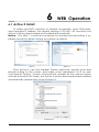
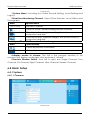
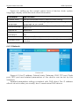
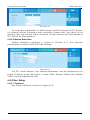
1
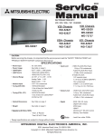
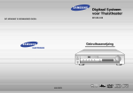
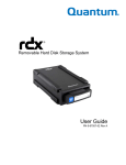
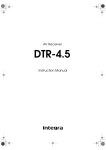
Digital Video Recorder User manual V4.0 Digital Video Recorder Declaration Declaration: Copyright ©2014 Without the written permission of the company, any company or individual should not extract, duplicate part of or all of contents of this manual and no spreading in any form. As the upgrade of the products or other other reason, the contents of manual will be upgraded aperiodically. Unless otherwise stipulated, the manual is used as a instruction. All statements, information and suggestions of the manual does not constitute any ostensive or implied guarantee. Product in kind prevail, final interpretations are owned by manufacturer. I Digital Video Recorder Declaration Safety Precautions Notice: Please do not place and install equipment directly under the sunlight or near heating device. Please do not install equipment at moist place or place with dust or soot. Please keep equipment installed horizontally, or install equipment in a stable place, avoid the equipment falling down. Please avoid liquid dropping on the equipment, make sure no objects filled with liquid on the equipment and prevent liquid from leaking. Please install the device in a well ventilated place, do not block the vents of the equipment. Please only use equipment within rated input/output. Please do not disassembly at liberty. Please transport, use and reserve the equipment within allowing humidity and temperature. Warning: Please do use the battery as requested, or it may lead to a battery fire, explosion or risk of burning! Please use the same type of battery when changing it. Please do use recomended cord sets(power cords), do use within the rated specifications. II Digital Video Recorder Contents Contents Safety Precautions............................................................................................................ II 1 DVR Function and Feature.......................................................................................... 1 1.1 Outline..................................................................................................................1 1.2 Function Features:............................................................................................ 1 2 DVR Appearance.......................................................................................................... 1 2.1 The Front Panel.................................................................................................. 1 2.1.1 The Front Panel(For informational purposes only, subject to object)........ 1 2.2 Rear Panel.......................................................................................................... 2 2.2.1 Rear Panel(For informational purposes only, subject to object).................2 2.3 Mouse Instructions............................................................................................ 3 2.4 Remote controls................................................................................................ 4 2.5 Input Method Introduction.............................................................................4 3 Connecting DVR............................................................................................................ 6 3.1 Hard Disk Installation........................................................................................ 6 3.2 Device Connection......................................................................................... 7 4 DVR Startup...................................................................................................................... 8 4.1 System Initialization........................................................................................... 8 4.2 Boot wizard......................................................................................................... 8 4.2.1 Login authentication........................................................................................................ 9 4.2.2 Common configuration................................................................................................... 9 4.2.3 Digitalconfiguration.......................................................................................................... 9 4.2.4 Record Setup.................................................................................................................... 10 4.3 Preview Interface........................................................................................... 11 5 DVR Menu...................................................................................................................... 12 5.1 Menu Options.................................................................................................. 12 5.1.1 Volume Settings................................................................................................................ 12 5.2 Main Menu Navigation................................................................................. 13 5.3 Main Menu....................................................................................................... 14 5.3.1 Record Query....................................................................................................................14 5.3.2 System Information.......................................................................................................... 16 5.3.2.1 Log Information................................................................................................. 17 5.3.2.2 Version Information.......................................................................................... 18 5.3.3 System Setup..................................................................................................................... 18 5.3.3.1 Common Set...................................................................................................... 19 5.3.3.2 Encoding parameters..................................................................................... 19 5.3.3.3 Rec Setup............................................................................................................ 21 5.3.3.4 Network................................................................................................................ 22 5.3.3.5 Video Detection............................................................................................... 24 5.3.3.6 PTZ Setup.............................................................................................................. 25 5.3.3.7 Display.................................................................................................................. 26 5.3.3.8 Restore Default.................................................................................................. 27 5.3.3.9 Image Color....................................................................................................... 28 5.3.3.10 P2P configuration........................................................................................... 29 5.3.3.11 DDNS................................................................................................................... 29 5.3.5 Advance Option..............................................................................................................30 5.3.5.1 Disk......................................................................................................................... 30 5.3.5.2 User........................................................................................................................ 31 III Digital Video Recorder Contents 5.3.5.3 Upgrade............................................................................................................... 32 5.3.5.4 Live Setup............................................................................................................ 33 5.3.5.5 Auto Maintain.................................................................................................... 34 5.3.6 Shut Down.......................................................................................................................... 35 6 WEB Operation............................................................................................................. 36 6.1 Active X install.................................................................................................. 36 6.2 IE Login............................................................................................................... 37 6.3 IE Login Interface............................................................................................ 37 6.4 Basic Setup....................................................................................................... 38 6.4.1 System.................................................................................................................................. 38 6.4.1.1 Common..............................................................................................................38 6.4.1.2 Network................................................................................................................ 39 6.4.1.3 User........................................................................................................................ 40 6.4.1.4 SMTP Setup.......................................................................................................... 40 6.4.1.5 DDNS Setup.........................................................................................................41 6.4.1.6 P2P Setup............................................................................................................. 41 6.4.2 Channel...............................................................................................................................41 6.4.2.1 Channel Setup...................................................................................................41 6.4.2.2 Motion Detection............................................................................................. 42 6.4.3 Rec Setup........................................................................................................................... 42 6.4.3.1 Common..............................................................................................................42 6.4.3.2 Playback.............................................................................................................. 43 6.5 Advance Setup............................................................................................... 43 6.5.1 System Maintenance..................................................................................................... 43 6.5.1.1 Disk Management............................................................................................ 44 6.5.1.2 Device Manage................................................................................................ 44 6.5.1.3 Default.................................................................................................................. 44 6.5.1.4 Log information................................................................................................. 45 6.5.1.5 Version.................................................................................................................. 45 6.5.1.6 Storage................................................................................................................. 46 6.6 Logout................................................................................................................ 46 7 Appendix....................................................................................................................... 47 7.1 Q&A.................................................................................................................... 47 7.2 Maintenance................................................................................................... 48 IV 1 DVR Function and Feature 1.1 Outline The item is a high-performance DigitalDVR, characterizing local previewing, multi-picture division displaying & local real-time storage of recorded files. It supports shortcut operating of mouse and remote managing and controlling. It has two ways of storage--Front storage & client-side storage. This product is a high-performance digital disk recorder. It has the functions of local preview,multi-split screen displays and local real video file storage capabilities.If also supports for mouse shortcuts,and has remote management and control functions.The product supports both the client front-end storage and client storage.This series DVR can not only be used independently,but also be networked to form a powerful Digitalmonitoring center.It has been widely used in domestic and foreign banks, telecom,power,justice,transport,community,factories,warehouses resources, water conservancy facilities etc. Areas and departments security.In addition,it also plays an important role in home security monitoring system. 1.2 Function Features: ●H.264 video condense format, Support DVR/960H Analog input. ●G.711U audio condense format. ●Windows-style user interface, embedded real-time Linux3.0 operating system. ●Support preview, recording, play back, backup. ●Supports dual stream. ●USB2.0, support backup, software upgrading & mouse operating. ●Support for multiple languages. 1 Digital Video Recorder Function Real-time Outline and Feature Function Brief Introduction Two video output, VGA & HDMI output. Record H.264 standard compression, timing recording. Storage Support SATA Hard Disk interface, video hard drive storage . Support time query, event query, channel query, log query Support DVR backup to USB memory sticks, portable Backup hard drive or a Digitalbackup to hard drive. DigitalOperati Support for remote client access, improve system ng safety. Mouse Support USB mouse operating, easily and quickly set Operating system parameters. Record Query PTZ Setup Pan-tilt Control Support PTZ presets point、automatic cruise. By analyzing video images, when the system detects a mobile signal reaches a preset sensitivity occurs, motion detection alarm is initiated and the linkage function. 1 2 DVR Appearance 2.1 The Front Panel 2.1.1 The Front Panel(For informational purposes only, subject to object) NO Button or indicator light 1 LED Indicators 2 Playback 3 Main Functions When working properly, the LED indicator lights up Increase reverse playback speed 1X, 2X, 4X,8X Play Press to start playback Pause/Frame Press to freeze playback to one frame, then press again to advance frame-by-frame 5 Slow play Press to slow playback speed by 1/2, 1/4, 1/8 6 Fast play Press to increase forward playback speed 1X, 2X, 4X,8X 4 1 Digital Video Recorder DVR Appearance 7 E-ZOOM 8 windows 9 10 11 12 PTZ REC MENU ESC 13 Navigation/OK When working properly, the LED indicator lights up. Press to switch between quad and split-screen displays Press to open the PTZ control window Press to open the PTZ control window Opens the main menu Opens the main menu Move cursor in menus;press to confirm selections 2.2 Rear Panel 2.2.1 Rear Panel ( For informational purposes only, subject to object) 3 5 2 4 9 4 10 3 8 8 5 6 7 1 2 9 10 7 No. Interface Connection instruction 1 Power input DC12V/5A 2 ON/OFF ON/OFF 3 Video output Output by TV/BNC 4 Input BNC 5 audio input audio input alarm input 4 /I alarm input alarm output I/O output for alarm RS 422 RS 422 for connecting PTZ 6 7 Network For connecting Ethernet 8 VGA For connecting VGA monitor 9 Audio output For connection audio output 10 HDMI For connecting HDMI monitor 2 6 1 Digital Video Recorder DVR Appearance 2.3 Mouse Instructions Mouse instruction Operate DVR through mouse left button, right button & scroll wheel. Mouse actions Function Click left mouse button 1. Select one of the options; 2. insertion cursor, enter or modify the value of a parameter. Click right mouse button 1. When interface not locking , click right mouse button, system menu pops up; 2. When interface locking, click right button on real-time preview interface, login interface pop up ; 3. Entered to main menu, to a submenu of PTZ control, click right mouse button on the menu interface, return to previous menu (except video playback interface); 4. Entered to close system interface, click mouse right button on the interface, return to preview interface. Double-click the mouse left button 1. When real-time preview multiple channels interface, double-click maximized channel display of one channel and return to the original state; 2. Double click the password input field on the login interface; 3. setting parameters (date, time, IP address, port number, bit stream value and user password) or user names mouse movements Select the menu or menu item. Mouse drag Drag progress bar to playback video. Slide mouse scroll wheel 1.Time setting; 2.Select the drop-down menu values; 3 Digital Video Recorder DVR Appearance 2.4 Remote controls 2 1 The remote control is the secondary input device. To use the remote control: 1. STANDBY:Press to turn standby mode 3 ON/OFF. 2. LOGIN/LOCK: If "Security" has been 6 4 enabled in the Setup menu, press to open the user password login screen. 7 5 3. Number/Channel buttons: While in menus, press buttons 0~9 to enter values; 8 during live viewing, press to view channels 9 in full-screen. 11 4. Multiple-window switch: Press to switch 10 between Single and split-screen displays. 12 5. PTZ: Press to open the PTZ control Interface. 13 14 6. MENU: Opens the main menu. 7. EXIT: Close menu windows. 8. Navigation/Enter: 15 • : Move cursor in menus up; • : Move cursor in menus right; • : Move cursor in menus left; • : Move cursor in menus down; 9. +/ - : In menus, press to adjust values. 10.Playback controls : • : Press to start playback. • : Press to increase forward playback speed 2X, 4X, 8X. • : Press to slow playback speed by 1/2, 1/4, 1/8. • : Increase reverse playback speed 2X, 4X, 8X. • : Pause or frame by frame playback picture; press for the first time to pause playback image; then continue continuous press, a second one frame every player; 11. STOP: Press to stop playback . 12. RECORD: Press to start manual recording, then press again to stop manual recording. 13. MUTE: Close live audio output. 14. AUDIO: Enter the volume control interface. 15. EXTRA: For the future use. 2.5 Input Method Introduction Input method includes lowercase and uppercase English letters. Clicking the Shift button on the left can switch the input method and the symbol“←”represents deleting incorrect input. 4 Digital Video Recorder DVR Appearance Uppercase English input Lowercase English input 5 3 Connecting DVR 3.1 Hard Disk Installation Hard Disk Installation: ⑴ Loosen the fixing screw on the cover, open the cover. ⑵ Align the four holes of hard disk button with hard disk mounting hole at the button of chassis. ⑶ Hold the hard disk with hand, turn over the chassis, fix the hard disk with screw at the indicated position. ⑷ After hard disk installed, turn over the chassis, fix the cover with screw. 6 Digital Video Recorder DVR Appearance Note: 1. If user requires high performance of hard disk, we recommend the dedicated security hard disk. 2. Before replacing the hard disk, please shut off the power first and then open the case. 3.2 Device Connection Show the DVR signal on the monitor by VGA / BNC / HDMI cable. If the camera possible PTZ control, contacting the PTZ RS485 cable A and cable B contact with the DVR RS485. 7 4 DVR Startup 4.1 System Initialization After connecting the device to the display, plug in the mouse, power cable and turn on the power switch on the rear panel, then start up the DVR. The system initialization interface is as shown in Picture 4-1. Picture 4-1 Notes: The insert figures in this user manual may not be the same as what you see on display. All figures here are just for reference. 4.2 Boot wizard After the device startup is complete, load the "Wizard" screen, as shown in Figure 4-2, you can make a simple configuration via the boot wizard, you can make the device into the normal working condition. After the normal startup, if you not choice the checkbox it will not appear next time. User find it at normall setting menu, or setting it after factory default. Picture 4-2 8 Digital Video Recorder DVR Startup 4.2.1 Login authentication After the normal startup, click mouse button and there will be a login dialogue, as shown in Picture 4-3 Then enters the user name and password in the input box.Choice the system language and login. (In the factory default state, the user name is admin, and the password is 12345) Picture 4-3 4.2.2 Common configuration Click“Basic configuration”,as shown in Picture 4-4, In this interface user can setup the device name, device ID, video format , Video Output and language, Screen saver and so on. Then enter the Digitalset or cancel exit the boot wizard. Picture 4-4 4.2.3 Digitalconfiguration Digitalconfiguration as Picture 4-5. Choice step back to general setting interface. Digitalconfiguration includes : network(IP address, gateway setting), other functions as below 5.3.3.1. Do next step enter the Video configuration, if you do not need to Digitalconfiguration settings. 9 Digital Video Recorder DVR Startup Picture 4-5 4.2.4 Record Setup Digitalconfiguration as Picture 4-6, select back on the Digitalsetting interface, user can set the video program, all settings as Picture 5.3.3.4. If you do not need to video configuration, choose to complete end of boot wizard, enter the preview interface. Picture 4-6 10 Digital Video Recorder DVR Startup 4.3 Preview Interface After the system is fully booted, it will enter into the default preview interface, shown in Picture 4-7. Picture 4-7 After the device normally starts up, the default setting is to preview in multi-screen display mode. Products with different channels has different amount of split screens to display. On the preview interface, you can set the appropriate date and time. On the bottom left of the screen, it shows the recording status of each video channel or alarm status icon. : this icon means monitoring channel is recording; : this icon means monitoring channel is in motion detection. 11 5 DVR Menu 5.1 Menu Options After login the system and back on the preview interface, click the right mouse button and it will pop up the Menu Options, shown in Picture 5-1. Then you can select options of the Main Menu, Volume Settings,the Main Screen Switching, Playback, PTZ Control and System Shutdown. In addition, you can set the channel display as follows: single-screen display, four-screen display, eight-screen display, night-screen display. It needs to set a specific number of channels to achieve single-screen display, four-screen display, etc.. The corresponding operation of the Main Menu Options will be illustrated in details in later chapters. Picture 5-1 Single-screen Display: Select one channel to display from CH1~CH8 . Four-screen Display: Divided into two groups to display (CH1~CH4 、 CH5~CH8 ). Night-screen Display: Display all channels CH1 ~CH8. Volume:Click to enter the volume setting interface,See chapter 5.1.1. Image Color: Click into the image color configuration interface. See chapter 5.3.3.9. Playback: Click into the Playback interface, See chapter 5.3.1. PTZ Setup:Click to enter PTZ control configuration menu, See chapter 5.3.3.6. Main Menu: Click and enter the main menu, See chapter 5.3. 5.1.1 Volume Settings Click right month button on the preview screen, select the volume option ont the shortcut menu, enter the volume setting menu, shown in Picture 5-2. 12 Digital Video Recorder DVR Menu Picture 5-2 Mute:ON/OFF volume. Volume:Volume adjustment bar, drag the slider to adjust the volume. Save:Save the volume settings. Cancel:Back preview interface. 5.2 Main Menu Navigation Record Query Log Info Info Version Common Conf Param Rec Setup Network motion detection Sys Setup PTZ Setup Display Main Menu Default Image Color P2P DDNS Disk User Advance Option Upgrede Preview Aoto Shutdown 13 Digital Video Recorder DVR Menu 5.3 Main Menu Main Menu includes Record Query,System Info,System Setup,Advance Option,Shutdown five parts, as shown in Picture 5-3. Select one and click the left mouse button to open the corresponding next menu options. Picture 5-3 5.3.1 Record Query After entering the main menu, open the "Record Query" menu or right-click to choose select "right-click" menu in the preview interface, switch to video query interface, shown in Picture 5-4. 1 2 3 5 7 Picture 5-4 14 4 6 8 Digital Video Recorder No. Name DVR Menu Function Specification Calendar In any play mode, select the recording type and channel number, click on the date you want to view, the timeline will update the recorded video for that day. Choose the Playback Channel Select the channel number to query. File List transfer button Select the date, channel number and record type, click into the video file list. Select the desired video file, double-click the left mouse button to start playing the video file. Backup Backup video file, the default format to avi Playback Control Area On the playback control bar, you can normally play, pause, fast forward, fast forward playback mode, you can select 1×, 2×, 4×, 8×, 16×, 1×which is played at normal speed; 6 Timeline Query to the video file, updated for the day that recording tracks on the timeline. Under the four-frame playback mode, display the selected four channels corresponding to four playback timeline, other playback mode displays only one playback timeline. Click on the green area to start from that point of time for playback. 7 Select type 1 2 3 4 5 8 video Timeline unit selection Select the type of video, you can choose the type for all types of video, timed recording, alarm recording and detection recording. Including 24h, 2h, 1h and 30min, the smaller units of time the greater the proportion of time zoom, you can adjust the exact point in time to play back video on the timeline. If the page is in the configuration, the timeline is 0:00 start amplification; if the page is being played, the places within the scope of the current playing time recently enlarged. 15 Digital Video Recorder DVR Menu In the file list bar, you can see the start time of the video file, video type, select a video file, you can view the video of recording start time, end time and file size, as shown in Figure 5-5. Picture 5-5 In the file list box, click to choose the video file selection box , showed icon “ √ ”, click this icon to backup the video files (external U disk), the files are “avi” format. You could also click to choose multiple video files selection box to backup those video files, users can also cancel this icon “ √ ” in the backup operation menu in the file list box, delate those video files that unwanted. 5.3.2 System Information Left-click the icon of “Info” in the main menu, shown as Picture 5-6 below, including “Log info” and “Version” of two sub-menus. 16 Digital Video Recorder DVR Menu Picture 5-6 5.3.2.1 Log Information Under the “Info” menu, please click “Log Info”, and then switch to the interface of “Log Info”. As shown in Picture 5-7. Picture 5-7 Viewing System Logs to access the logs and search for these events on one day a certain period of time. Type: Select the type of information you request. Start Time/End Time: Enter the time to find the logs. Search: Search for logs according to criteria. PgUp/PgDn: You can view all logs through the PgUp/PgDn. Clear: Clear all information. Cancel: Return to the former menu. Specific Steps: Enter the log search menu, set search parameters, click the Search button to begin search, If logs matching the search criteria are 17 Digital Video Recorder DVR Menu found, it will be displayed in a list, To view all logs through PgUp/PgDn button. 5.3.2.2 Version Information Click “Version” icon under “Info”, switch to interface as Picture 5-8 shows. Picture 5-8 Users can find system version, including serial No, model number, system version,Version Date. Serial No.: Showing the serial No.of the DVR. Model number: Number of main board. Version: System version number. Date: Program created date. 5.3.3 System Setup Left-click the icon of “Sys Setup” in the main menu, shown as Picture 5-9 shows. 18 Digital Video Recorder DVR Menu Picture 5-9 5.3.3.1 Common Set Click “Common Config” icon under “Sys Setup”, switch to interface as Picture 5-10 shows. Picture 5-10 System Time : System date and time of DVR. Default Language : the default language of the system boot, which is English, but, at present, also supports Chinese, Polish, Czech, Russian, Thai language, Hebrew, Persian, Bulgarian, Arabic, German, French, Portuguese, Turkish, Spanish, Italian, and Hungarian. Record Mode : Overwrite automatically, ie., DVR will automatically cover the previous record if hard disk is full. Device ID : Reserved. Video Standard : PAL or NTSC. Standby Time: It means standby time of system without operation for DVR If time exceeds the standby time, then you should re-login in system so as to operate DVR. Default standby time is 30 minutes. And standby time range is: 1 to 120 minutes. Open the wizard:☑means boot the wizard function. Device name:Set the name of the device. Default : Restore all specifications or parameters of common setup to be factory default specifications. Save: To save specifications or parameters of common setup. Cancel : Return to the former interface. 5.3.3.2 Encoding parameters Click “Param” icon under “Sys Setup”, switch to interface as Picture 5-11 shows. Resolution,Frame Rate, Stream Type, Bit Rate, Sub-stream can be set under “Param” Interface. 19 Digital Video Recorder DVR Menu Picture 5-11 Channel: Select the channel number Enc Mode: Standard H.264. Resolution: The type of main stream resolution is the encoding parameters of client IPC, generally include D1/720P/1080P etc, the type of sub-stream resolution include D1/VGA/CIF. The resolution is bigger, the better the video quality, and the larger the hard-dish space occupied. On the contrary, the resolution is smaller, the worse the video quality, the smaller the hard-ship space occupied. Frame Rate: P type: 1 frames / sec-25 frames / sec; N type: 1frames / sec-30frames / sec. Stream type: Select video stream or audio stream.. Bit Rate: Setting bit rate can change the picture quality, the larger the bit rate and the better the picture quality. main stream/subcode flow frame rate:User according to the demand to select encoding video frame rate.general the image quality, frame rate and resolution parameters setting higher, the more take up disk space. Notice: code flow resolution and frame rate is restricted by different type device and program vision. Default: Recover all the encoding parameter to default values. Save: Save the parameters on preview configuration menu. Cancel: Return to the former interface. Overlay Set Override the settings interface, as shown in Figure 5-12. Cover Set,Time title, and Channel title can be set under “Overlay Set” Interface. 20 Digital Video Recorder DVR Menu 图 5-12 Block set:Set the channel preview and playback occlude areas. Time tile:Set the playback channels display position. Channel title:Set the playback channels system time display position. Save:Save preview configuration interface setting parameter values. Cancel:Return the management interface. 5.3.3.3 Rec Setup Click “Rec Setup” icon under “Sys Setup”, switch to interface as Picture 5-13 shows. Picture 5-13 Channel: Select a channel to record. There are 2 choices: single channel and all channel. A specific channel should be chosen for choice of single channel. Enable: Make enable is open. ☑start video. Week: Choice the one day or each day start video during one week. All Day: Record the whole day. ☑whole day video. Period: If not all day record, then any four periods can be set to record during the periods. Default: Restore parameters of record setup to be default ones. Save: Save parameters of current interface. 21 Digital Video Recorder DVR Menu Cancel: Return to the former interface. 5.3.3.4 Network Click “Network” icon under “Sys Setup”, switch to interface as Picture 5-14 shows. Picture 5-14 DHCP: after selecting the option, set the access mode of the local IP address to be automatic access, or you should manually set up the IP address. IP Address: IP address of DVR. Subnet Mask: Subnet mask of DVR. Default Gateway: Default gateway of DVR. TCP Port: Reserved. RTSP Port: RTSP data port of DVR. HTTP Port: Port for visit by IE browser for DVR. Primary DNS: It is usually offered by local ISP. Your IP address of domain name server is entered here. Secondary DNS: Start secondary DNS when the primary one does not work. Broadcast: Reserved. MAC Address: MAC address of DVR. Default: Restore all parameters of Digitalsetup to be defaulted ones. Save: Save parameters of common setup interface. Refresh: clicking Save to save the parameters to the device after finishing all the parameters setup and click Refresh to acquire the latest configuration information of the device. Cancel: Cancel the set Digitalof current interface. DigitalService 22 Digital Video Recorder DVR Menu Click the Digitalservices, enter Digitalsettings service interface. Can send you email when alarm occurs,pic 5-15. Open UPNP, all the PC show DVR icon at Digitalplaces, click two times and login with password to view. Notice: Router must support and open Upnp function when you use it, shown in Picture 5-15. Picture 5-15 Double-click the mail settings at the Digitalservice, enter the mail setting interface. Can send you email when alarm occurs, shown in Picture 5-16. Picture 5-16 SMTP server: The address of the mail server, which can be an IP address and a domain name (domain name needs the confirmation of the correct DNS setup to be resolved correctly). 23 Digital Video Recorder DVR Menu Port: Port number of the mail server. User name: User name of the sender’s mail. Password: Password of the corresponding user name. Receiver: The warning information can be sent to the designated receiver via mail, three recipients can be set up. Sender: Setting the EMAIL address of the mail sender. Interval: Interval for sending the alarm mail. Default: Setting all the parameters in the Email Setup interface to be default. Save: Saving the parameters in the Email Setup interface. Return: Going back to the former management interface. 5.3.3.5 Video Detection Click “Motion Detect” icon under “Sys Setup”, switch to interface as Picture 5-16 shows. When the system detects a mobile signal reaches a preset sensitivity occurs, motion detection alarm and the linkage function will be initiated by analyzing the video image. Picture 5-17 Type : video detection including motion detect alarm and Video loss alarm. Channel No: Select the motion detection channel. 2 option: Single and All), for the Single channel, you need to choose the particular channel. ON/OFF:☑ open video detection function. Sensitivity: 7 values can be set for the sensitivity. System locale:Set the trigger video detection area. Buzzer on :☑ Open Buzzer Smtp Enable:☑ open mail alarm, system send mail when alarm occurs, for example, alarm event, capture picture, device name and device ID. 24 Digital Video Recorder DVR Menu Record channels:☑ open the trigger video, choice the video channel, system alarm channel when alarm occurs. Default: Recover all the alarm setting parameters to the default values. Save: Save the set parameters of current menu. Cancel: Don’t save the set parameters of current menu. 5.3.3.6 PTZ Setup In the preview screen,select a channel preview window, click the right mouse button and click PTZ control options, the preview screen will switch to the single-channel display, and PTZ control interface appears in the lower left corner, as shown in Picture 5-18 Picture 5-18 Adjusts the movement speed of the PTZ, (click middle button of the wheel to set speed)Directional Buttons controls the movements and directions of the PTZ. zoom, focus, iris can be adjust by increase "+", reducing the "-" button. Presets position: Can select certain Presets to Configure Preset or Call Preset, Clear Preset, range from 1 - 255. Presets point: The presets box choose a certain preset point need go to, After clink on the swith icon, PTZ will jump to that location. Click the Presets button, like pop-up screen shown in Picture 5-19, you can view the setting status of presets from 1-255; Picture 5-19 Cruise Settings: Set the function of cruise, and related presets setting of cruise, including dwelling time and cruising speed. Shown in Picture 5-20 and Picture 5-21; 25 Digital Video Recorder DVR Menu Picture 5-20 Picture 5-20 Stay Time: Stay time on the Preset. Cruise speed: Speed for Cruise. Start Cruise: Start Cruise, and patrol in fixed path. Auto Scan: Clear all preset point. Notice: the DVR supports maximum 255 preset point, however, it is also affected by the PTZ Camera itself, for different PTZ Camera, the number of preset point supported could vary a lot. 5.3.3.7 Display Click “Display” icon under “Sys Setup”, pop up the display configuration interface, could modify the display resolution and channel names, shown in Picture 5-22. 26 Digital Video Recorder DVR Menu Picture 5-22 Time Title/channel title: ☑ After the selected can display system time/ channel name. Channel Name: Click on the name of the channel can be modified to display the name of each channel,as shown in Figure 5-23. Resolution: It means the resolution of video output of DVR. Optional resolution: 1024×768 、 1280×720 、 1280×1024 、 1920×1080. Default resolution is 1280×720. It will be valid only after DVR is re-started with all specifications saved. Picture 5-23 5.3.3.8 Restore Default Click “Default” icon under “Sys Setup”, transfer to the interface of default,as shown in Figure 5-24. 27 Digital Video Recorder DVR Menu Picture 5-24 According to user selection, you can set the parameters of restore default for “Common”, “User”, “Record Setup” and “NetWork”. 5.3.3.9 Image Color Click “Image Color” icon under “Sys Setup”, pop up the video configuration menu, then can configure the video properties of IPC. As shown in Figure 5-25. Picture 5-25 Channel: Select the Channel number. Bright: Bright adjustment. Contrast: Contrast adjustment. Saturation: Saturation adjustment. Color: Color adjustment. Default: Recover all the video configuration parameters to default value. Save: Save configured parameters value on video configuration menu. Return: Return to last management menu. 28 Digital Video Recorder DVR Menu 5.3.3.10 P2P configuration Double click left mouse P2P configuration, enter P2P setting interface, shown in Picture 5-26. P2P including mobile client remote monitoring, can be add mobile client by scanning the QR code. Picture 5-26 5.3.3.11 DDNS Double click left mouse DDNS configuration, enter DDNS setting interface, shown in Picture 5-27., can be set up remote through the domain name. Picture 5-27 DDNS Type: DDNS Types can be chosen via DDNS. (currently the list supports various DDNS, including ORAY DDNS, 3322 DDNS, TZO DDNS and DYNDNS DDNS. These DDNS can be multiple operated according to users needs and setup. ) Enable: enabling DDNS domain resolving function. 29 Digital Video Recorder DVR Menu DDNS refresh time:Setting refresh time, the number in seconds. User name: the account registered in the DNS service provider. Password: the password to the account registered in the DNS service provider. Domain name: the domain name registered in the DNS service provider. Refresh: clicking Save to save the parameters to the device after finishing all the parameters setup and click Refresh to acquire the latest configuration information of the device. Save: saving the parameters in the DDNS setup interface. Return: going back to the former management interface. When DDNS is successfully configured and enabled, you can type in the registered domain name in the IE address bar directly to link the Web page of the device. 5.3.5 Advance Option Left-click "Advance Option" in the main menu, as shown below, including disk management, user accounts, equipment upgrades, and configuration of four sub-menu preview 5-28. Picture 5-28 5.3.5.1 Disk Click “Disk” icon under “Advance Option”, will switch to the interface of Disk Manage, as shown in Picture 5-29. 30 Digital Video Recorder DVR Menu Picture 5-29 If the devices have connected the HDD successfully, the HDD manage list will show the information of HDD.You have to format the HDD if the HDD is the first time to connect; If the system detects that do not need to format the hard disk, the HDD status will displays “normal”; If do not connect successfully or could not detect hard disk, will displays the warning “Not connected the HDD”. HDD No.: The number of HDD that connect the system. State: Detect the current working status of HDD, you could use only that displays “normal”; After formatting is completed, you need to restart DVR, the status displays "in use". Total Capacity: The total available HDD capacity, the single HDD capacity can not exceed the maximum capacity: 4TB. Residual Capacity: Display the residual capacity of the current HDD; Device Type: SATA. Refresh: Refresh HDD information in the list; Format: Formatting the HDD, select the HDD that needs to be formatted firstly, and then click the "Format" button, pop-up warning dialog "formatting will result in the selected HDD recording data loss, confirm that you want to continue?", If confirm to format then click on the "OK" button, otherwise click "Cancel". Return: Return to the former management interface. Note: After formatting the HDD, you need to restart the device. 5.3.5.2 User Click “User” in “Advance Option” interface, then interface of user management will be out. As followed picture 5-30 shows. 31 Digital Video Recorder DVR Menu Picture 5-30 User List: List added users. “admin” is super user/administrator, and we cannot change its privilege, but only its password. Other general users have no privilege of adding, modifying or deleting. Privilege: Privilege list of users. It includes PTZ control, playback, parameter setup, query log, advanced configuration, channel management, query parameter, backup /shut down/ logout. Add: To add a new user, which can be only done by super administrator--admin. Click “Add”, then enter user name and password, select privilege and save the parameters. Modify: To change information of users, which can be only done by super administrator--admin. First, choose a user, click “modify”, then enter old password and new password, modify privilege, and finally save the parameters. Delete: To delete user, which can be only done by super administrator--admin. Return: Return to former interface. 5.3.5.3 Upgrade Click “Upgrade” icon under “Advance Option”, transfer to the interface of Upgrade Management, As followed picture 5-31 shows. 32 Digital Video Recorder DVR Menu Picture 5-31 If the device have detected upgrade files in the U disk, the related information of upgrade package (number, name, size, date) will be displayed. U disk Upgrade steps: Copy the upgrade file (named should be the format update_dvr.tgz) to the root directory of U disk, connect this U disk to the device's USB port, if did not display the upgrade file in the list ,please refresh the interface ( If the upgrade package still cannot be searched out , please check whether the USB port connect well with the U disk , and also check whether the upgrade file name is correct). After the upgrade file appears, select the upgrade file, click the "upgrading" and begin to upgrade; If you don't want to upgrade, click cancel to return. Note: During the upgrading process, please do not cut off the power or take off your U disk. After the upgrading, your system will restart automatically. (This process will takes about 3 to 5 minutes.) Here, we advice you to restore factory Settings after the upgrading. 5.3.5.4 Live Setup Double click left mouse setting the scene, enter setting the scene interface, shown in Picture 5-2. 33 Digital Video Recorder DVR Menu Picture 5-32 Channel list:Set video input type of the channel, set to 720P or 960H. Default:Restoration site parameters, set to default values. Save:Save the parameter values of the current interface settings. Cancel : Do not save the parameter values of the current interface settings, return to the previous interface. 5.3.5.5 Auto Maintain Click the automatic maintenance icon in the advanced option interface and the automatic maintenance setup interface will pop up, as followed picture 5-33 shows. Picture 5-33 User can themselves set the system to be automatically rebooted. Automatically rebooting system can be set in a fixed time periodically. Click OK to save after finishing the setup or click Cancel otherwise. 34 Digital Video Recorder DVR Menu 5.3.6 Shut Down Click “Shut Down” icon in the main menu, move on to shut down the system interface. Therefore, the system can be canceled, restarted, and shut down, as followed picture 5-34 shows.. Picture 5-34 Logout: Logout the current user, switch to user login interface. Reboot: Reboot the device. Shut down: Shut down the device, just like computer safe shutdown mode. 35 6 WEB Operation 6.1 Active X install To make sure DVR connects to Internet successfully, open IE Browser, input required IP address, the default setting is 192.168.1.168, and then the Active X will be downloaded and installed automatically Notice: 1.For WIN 7, could have problems for backup and recording, if so, please check the Admin setting, procedure as follows: WIN7-1 WIN7-2 2.The Active X can't be loaded? Please adjust the security level and firewall setting to the lowest, and make some adjustment to IE as well: Tool-Internet Option- Custom level-ActiveX- enable all the options below ActiveX and click OK! Finally, the Active X will be downloaded and installed automatically, please refer to the Picture 6-1. Picture 6-1 36 Digital Video Recorder WEB Operation 6.2 IE Login After the plug-in is installed, login interface as below Picture 6-2, entering the user name and password. The default user name is admin, and the password is 12345, click the login then can remote login. Picture 6-2 6.3 IE Login Interface After logining the client sucessfully, entering live preview interface and video connection automatically. The interface as below Picture 6-3: 1 2 3 5 4 37 Digital Video Recorder WEB Operation Picture 6-3 1.System Menu. Including Live Video Record Setting, Local Setting and Logout. 2.Real-time Monitoring Channel. Open/Close Preview, Local Video and Photograph. Mark Specification CH1-CH16 Preview Channel. Open or close corresponding preview channel. Click the button, begin recording, the video saves in computer hard disk. Click the button, capture images, the picture saves in computer hard disk. 3.Open/Close All Channeles Preview Image Mark Specification Open all preview channeles. Close all preview channeles. 4.display modes to choose. The left is the preview window in full screen,in this display mode,right-click and select "retreat”. 5.Preview Window Switch. from left to right are: Single Channel, Four Channel, Six Channel, Eight Channel, Nine Channel, Sixteen Channel. 6.4 Basic Setup 6.4.1 System 6.4.1.1 Common Picture 6-4 38 Digital Video Recorder WEB Operation Figure 6-4, setting up the current system time of device, date, system language, display resolution and other information. Parameter Specification System Time Default language Set up the system time of device than saving. Set up the device language, you can change the language as you need. Can be set to automatically overwrite when the hard disk is full. Reserved. The video standard of device must be same with the IPC. HDMI and VGA output resolution of device can be set. Lock time of local time can be set , the time is 1-120 minutes. Record Model Device ID Video Standard Resolution Standby time 6.4.1.2 Network Picture 6-5 Figure 6-5, the IP address, Subnet Mask, Gateway, DNS, TCP port, Data port, HTTP port and related parameters of the device can be set by the interface. Related parameters setting consistent with DVR client; The IP address effects at once after you modify, don’t need restart DVR device. 39 Digital Video Recorder WEB Operation 6.4.1.3 User Picture 6-6 Figure 6-6, you can add or delete user, modify the information and rights of user by the interface; Related parameters setting consistent with DVR client. 6.4.1.4 SMTP Setup Picture 6-7 Figure 6-7, when alarm message appears, mails can be sent to designated mail address through the setup of this page. The relevant parameters should be set up the same with the DVR port. 40 Digital Video Recorder WEB Operation 6.4.1.5 DDNS Setup Picture 6-8 Figure 6-8, the DVR can be set up remotely via domain name through this interface and the relevant parameters setup should be the same with the DVR port. After determining the date in this interface, videos of associated channels can be checked according to the video types. Relevant parameters should be the same with the DVR port. 6.4.1.6 P2P Setup Picture 6-9 Figure 6-9, the DVR can be set up remotely via domain name through this interface and the relevant parameters setup should be the same with the DVR port. 6.4.2 Channel 6.4.2.1 Channel Setup The interface of encoding parameters as below Picture 6-10, relevant parameters are same with DVR setting. You can get parameters of Main-stream and Sub-stream of IPC device 41 Digital Video Recorder WEB Operation Picture 6-10 You can get parameters of Main-stream and Sub-stream of IPC device of channel access (coding mode, resolution, frame rate, the value of the stream), also can set the value of stream of Main-stream and Sub-stream of IPC device by the interface. 6.4.2.2 Motion Detection Motion detection interface is shown in Picture 6-11, the relevant parameters consistent with DVR-side settings. Picture 6-11 The IPC's Main Stream, Sub Stream parameter can be obtained in this page (Coding mode, Resolution, Frame Rate, Stream Value) the Stream Value can be adjusted as well. 6.4.3 Rec Setup 6.4.3.1 Common Rec Setup interface is shown in Figure 6-12. 42 Digital Video Recorder WEB Operation Picture 6-12 You can set up the channel recording as timetable by the interface, relevant parameters are same with DVR setting. 6.4.3.2 Playback Rec Playback interface is shown in Figure 6-13. Picture 6-13 After determining the date in this interface, videos of associated channels can be checked according to the video types. Relevant parameters should be the same with the DVR port. 6.5 Advance Setup 6.5.1 System Maintenance Click Advance Setup, than you can find Disk, Device Manage, Default, 43 Digital Video Recorder WEB Operation Log and Version. 6.5.1.1 Disk Management You can format the disk (when you use the hard disk to record first time, you need format the disk first), you can find the information of hard disk(Disk Number, State, Total capacity, Residual Capacity and Device Type), as below Picture 6-14. Picture 6-14 6.5.1.2 Device Manage You can restart and update the device of DVR by remoting, as below Picture 6-15. Picture 6-15 6.5.1.3 Default You can restore the default parameters of DVR by remoting, the method of setting is same with local setting, as below Picture 6-16. 44 Digital Video Recorder WEB Operation Picture 6-16 6.5.1.4 Log information You can find specific log information by log query. Specific steps: Set up the type and time of the journal you need (as below Picture 6-17, you can recall the calendar to choose the date by clicking the blank frame of start time and begin time), click “query” to query the journal, if there has recordings of journal, it will display on list, you can check all journales by page up/page down. Picture 6-17 6.5.1.5 Version User can check the version information of the system, including serial number of product, model number, version number and version date. As below picture 6-18. 45 Digital Video Recorder WEB Operation Picture 6-18 6.5.1.6 Storage In Storage configuration, the user can set up the save path of video file (preview video file) in computer, remote file download and capture image. as below Picture 6-19. Picture 6-19 6.6 Logout Click the logout icon , back to the login screen. 46 7 Appendix 7.1 Q&A 1. How to do when can’t detect the hard disk? Answer: If the system does not detect the hard disk, kindly please check the data line and the power line of hard disk whether are connected well, whether there is a problem about the interface of hard disk on the motherboard, or kindly please check hard disk whether is supported by the DVR in specification. 2. After modifing password, what can you do when you forget the password? Answer: When the administrator forget password, kindly please get in touch with our technical staff. The easy to remember and relatively safe password is recommended when you set the password (if you have security needs, kindly please don’t try to set simple passwords such as 123). 3. what results will maybe happen due to the heat when DVR is working? Answer: It will produce some heat when DVR is working, kindly please put the DVR in the place where is safe and ventilated to stop the stability and life of the system be affected due to long-term high temperature of DVR. 4. Whether can use if i install the hard disk drive of computer to DVR? Answer: If the hard disk you use can be supported by the system of DVR, it can work, but you need note, if the DVR begins to work, all datas in your hard disk will loss. 5. Whether can playback when recording? Answer: Yes. 6. Whether can remove a part of video recordings of hard disk of DVR? Answer: Considering the security of document, you can’t remove a part of video recording, if you need remove all video recordings, you can format the hard disk. 7. Why can’t login to DVR client? Answer: Kindly please check configuration of Digitalconnection whether is right, connection of RJ-45 interface whether is fine, if also can’t work, kindly please check whether the user name and password are right. 8. Why can’t find any recording information when playback? 47 DigitalVideo Recorder Appendix Answer: Kindly please check whether the connection of data line of hard disk is good, whether the time of system is changed, whether the query condition that is setted can’t save video files. If also have the question after restarting, kindly please check whether the hard disk is damaged. 7.2 Maintenance 1. When DVR shutdowns, kindly please don’t turn off the power switch directly, should use the shutdown button of system to avoid data loss or damage of the hard disk. 2. Ensure DVR away from high temperature heat source and place. 3. Remove the dust deposited in the body timing, keep the good ventilation around chassis, it is good for radiating. 4. About the audio/video signal line and RS-485 interfaces, kindly please don’t hot swap, or these port will be damaged easily. 5. Check the HDD power cable and data cable of the DVR regularly and look whether they are aging. 6. Avoid the audio/video signal effected by other circuits and devices as much as possible, prevent the hard disk damaged by electrostatic or induced voltage. 48