1
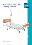
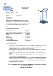
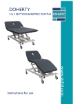
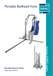
User Instructions
www.sidhil.com
2260 Independence Versa
Electrically Operated Profiling Bed
Thank you for choosing a Sidhil Independence electrically profiling acute care bed. This
user manual should be read carefully before you use your bed as it contains important
information regarding safe operation and maintenance in order to provide long lasting and
reliable service.
Please ensure that you understand all the instructions, if you have any questions concerning
the operation and maintenance of the bed please contact your supplier who will provide
you with expert professional advice.
In line with our policy of continuous improvement we welcome any suggestions that could
lead to product improvement.
This product is manufactured to comply with the essential requirements of the
Medical Devices Directive 93/42 EEC
Note: This bed has been disabled via the lockout box found at the foot end
of the bed. To enable functions, turn knobs clockwise to the vertical
position (see page 13).
Contents
Section
1.
2.
3.
4.
5.
6.
7.
8.
9.
10.
11.
12.
13.
14.
15.
16.
17.
18.
19.
Title
User Warnings
Introduction
Parts Identification
Positioning of the Bed
Installation & Preparing for Use
Operating your Independence Bed
Electrics
Braking & Steering
Bed Stripper
Bed Extension (2260 versa only)
Active Seat System (2260 versa only)
Side Rails
Lifting Pole
Do’s & Don’ts
Cleaning Procedure
Maintenance Procedure
Spares List
Specification
Warranty
3
Page
4
4
5
6
7
8
9
14
14
15
15
16
18
19
20
21
23
24
25
1. User Warnings
Warnings in these user instructions identify possible hazards and/or conditions which
should be followed at all times. Failure to do so could result in serious injury or even death.
WARNING
Misused electrical equipment can be hazardous.
Accessories that have not been approved for use with the bed
should not be used.
Electrically operated beds should not be used in the presence of flammable gases.
Electrically operated beds should not be used in operating theatres.
2. Introduction
Your Independence bed is suitable for patients of high dependency and those who are a
moving and handling risk. The bed is also appropriate for high dependency patients whose
clinical needs necessitate positioning with minimal handling.
It is possible for patients, with permission/guidance from the carer, to adjust the bed via a
touch button handset, allowing the occupant to choose their position as required.
The bed is designed to support one person up to 222kg (35 Stones) in weight. This total
weight should not be exceeded.
Standard features:
• Electrically operated backrest and knee break
• Active seat position (2260 Versa bed only)
• Electrically operated height adjustment
• Electrically operated tilt function, both forward and reverse
• Electric and manual CPR functions
• Manual leg elevation
• Extendible mattress platform (2260 Versa bed only)
• Removable mattress platform plastic panels
• Central locking castors with steering and braking functions
• Removable head and foot boards
4
3. Parts Identification
1
2
3
4
5
6
7
8
9
10
11
12
13
14
15
16
Head Board
Mattress Platform
Mechanical CPR Release Lever
Backrest Actuator
Knee Break Actuator
Height Adjustment Actuators
Brake Pedal
Control Box
Lockout Box
Central Locking Castor
Bed Stripper
Foot Board
Carer Handset
Leg Rest Section
Adjustable Side Rails
Backrest
16
15
1
14
13
12
2
3
11
4
10
5
6
7
8
5
9
4. Positioning of the Bed
The Independence must be positioned away from the wall to get the full use of
all the bed functions. To ensure the head board clears the wall when using the
full trendelenberg movement (see below), the bed needs to be positioned so
that the chassis at the head end is at least 660mm (26”) away from the wall (see
below). Trendelenberg function cannot be used if accessories, such as the lifting
pole, are attached to the head end.
Bed in full Trendelenberg
Minimum distance from centre of Chassis to
wall: 660mm (26”)
Where possible familiarize yourself with the full range of movements of the bed
before it is used by a patient.
6
5. Installation and Preparing for Use
Before attempting to install your Independence bed ensure the instructions have been read
and fully understood. No tools are necessary for the assembly of your bed and the
procedure is as follows:
• Remove the head and foot ends from the box.
• Slot the larger board into the sockets at the head end of the bed. Note: Ensure the
board is orientated with the metal bracket pointing towards the wall.
• Slot the small board into the sockets at the foot end of the bed.
• Un-box the plastic mattress panels and position them on the relevant part of the frame,
ensuring that they are clipped in place.
• Plug the mains cable into an appropriate mains socket outlet.
• The bed must now be ‘initialised’. Using the carer handset raise the bed to its
maximum height, once at full height keep the button held down for a further ten
seconds. The bed is now initialised. This procedure should be periodically carried out.
Note: See pages 9 and 12 for correct operation of the handsets.
• The bed can now be manoeuvred into its correct position and is ready for use.
• For side rail fitting see page 16.
WARNING
Ensure that the mains cable is not in tension when connected to the power supply.
Ensure that all cables and handsets are clear of any moving parts
on the bed to prevent them becoming tangled or damaged.
Note: This bed must only be used with a mains supply of 240V, 50Hz. If
this product is to be used outside of the UK seek professional advice as to
the compatibility of this product with the mains power supply type.
7
6. Operating your Independence Bed
General Safety
When the bed is operated, ensure that obstacles such as over bed tables and other
furniture are not in the way.
Check that all electrical cables are free from tension and are positioned as to avoid both
patient and carer accidents.
Ensure that the mattress used is of correct size and type. A range of dynamic and static
pressure relieving/reducing mattresses are available from Sidhil Ltd.
When positioning the bed ensure that the patient is positioned appropriately and ensure
that the occupant is aware in advance of each action taking place.
The brakes should always be engaged when the bed is not in motion.
Ensure these user instructions are kept in a safe place at all times. Additional copies are
available from Sidhil Ltd.
8
7. Electrics
i) Carer Handset
The carer handset is designed for use by the carer only. The backrest, bed height, knee
break, trendelenberg (two-way tilt), and emergency CPR functions can be controlled from
this handset. To adjust the position of the bed, depress the relevant button until the desired
point has been reached and then release the button.
Backrest -
To raise the backrest depress
To lower the backrest depress
Bed Height -
To raise the bed depress
To lower the bed depress
Knee Break -
To lift the knee break depress
To lower the knee break depress
Trendelenberg -
To tilt the head end up depress
To tilt the head end down depress
CPR -
To flatten the bed and lower the bed
9
Manual Knee Break Operation
The knee break button on the handset adjusts the height or angle of the thigh section (1)
depending whether or not the leg stay support is being used. To raise the legs:
•
•
•
•
Lift the leg section (2)
Lift the leg stay (3)
Position the leg stay into the channel, found to the underside of the leg section frame.
The leg stay is now locked in position, pressing the knee break button will now
raise/lower the leg section.
1
3
2
Trendelenberg/Tilt Function
When in tilt, in order to level the bed the opposite button should be pressed and held until
the bed stops. This indicates that the mattress platform is now level.
To continue tilting the bed in the opposite direction, re-press the same button again and
hold down until the desired angle is reached.
10
Emergency CPR Function - Electric
Depressing and holding the
button automatically flattens the backrest, lowers the
bed and levels the mattress platform.
WARNING
If a function has been locked out on the lockout box
it will remain locked when the CPR button is depressed.
When operating the CPR function ensure that all limbs/hands and equipment
are clear in order to prevent trapping or injury.
NB: See page 13 for details on the lockout box.
Emergency CPR Function - Manual
The backrest and knee break can be
levelled simultaneously via a
mechanical CPR handle, located on
both sides of the bed.
To operate the mechanical CPR, pull
the lever upwards and apply light
pressure to the backrest at the same
time to push it down.
NB: The manual CPR function does
not lower or level the mattress
platform, this can only be achieved via the CPR button on the handset.
11
ii) Patient Handset
An additional handset is supplied for use by the patient. This handset allows the patient to
control the backrest, bed height and operate the knee break and backrest simultaneously
(auto contour). To adjust the position of the bed, depress the relevant button until the
desired point has been reached and then release the button.
Ensure that the patient has been instructed on how to operate the bed
via the handset.
Backrest -
To raise the backrest depress
To lower the backrest depress
Bed Height -
To raise the bed depress
To lower the bed depress
Auto Contour - To contour the platform depress
To flatten the platform depress
NB: It is not possible to operate only the knee break with the patient handset, the backrest
will contour with it.
WARNING
Ensure that only those suitable to use the handsets are given access.
12
iii) Lockout Box
Located at the foot end of the bed is a lockout box. This prevents unauthorised operation
of selected functions.
To lock out the selected function, the circular knob on the box should be turned
anticlockwise to the horizontal position so that it is facing the closed padlock symbol ‘
‘.
NB: The lockout box disables the selected functions on both the patient and carer
handsets.
Knee Break
Lockout Control
Backrest
Lockout Control
Bed Height
Lockout Control
NB: Consideration should be given to locking out the controls whilst the bed
is left unattended.
iv) Battery Backup
A battery backup feature will automatically be engaged when the bed is disconnected from
the mains supply. This allows emergency or temporary operation of the bed for a limited
period but will vary depending on the features used.
The bed should remain connected to the mains supply at all times for normal use, to
ensure that the batteries remain fully charged. This will also prolong the life of the batteries.
13
8. Braking & Steering
There are two linked brake pedals at the foot end of the bed which control all the
castors simultaneously.
• When the pedal is in the ‘steer’ position it locks one castor on the
bed so that it cannot swivel. This allows the bed to be steered
when being pushed from the head end of the bed.
• When the pedal is in the ‘free’ position no castors are locked
allowing all to swivel freely.
• When the pedal is in the ‘brake’ position three castors are locked
and the bed then cannot move.
9. Bed Stripper
An integral extending bed stripper is
incorporated into the foot end of the bed to
assist with linen changing procedures. Pull bed
stripper out to use.
14
10. Bed Extension (2260 versa only)
The bed is fitted with an integral 200mm bed extension which allows the bed to be
adjusted in length, according to patient size / needs.
To operate the extension:
•
•
•
•
Unscrew the hand wheels on both sides of the mattress platform (1)
Pull out the extension with both hands (2)
Unfold extension panel (3)
Re-tighten the hand wheels
3
1
2
11. Active Seat System (2260 versa only)
The active seat system is designed to improve patient comfort and reduce the amount of
slip down the bed when raising the backrest. As the backrest is adjusted the seat section
moves accordingly.
15
12. Side Rails
Assembly
1. Orientate the side rails so that the locking mechanism release plunger is at the foot
end of the bed and is pointing outwards.
2. Position the side rail pivot brackets behind the support tubes.
3. Slide the two bolts through both the clamp brackets, the support tubes and through
the back of the two pivot brackets.
4. Fasten in place with the supplied washers and nuts. Ensure that the nuts are tight.
5. Repeat the above procedure for the second side rail.
6. The side rails are now assembled and ready for use.
Operation
Lowering the Side Rail
Lowering the side rail: To release the side rail pull the spring loaded release plunger
outwards. Whilst holding out, gently lower the side rail.
Release plunger
16
WARNING
Side rails must only be used with the correct size and type of mattress
for the Independence bed, as approved by Sidhil Ltd.
IMPORTANT: Refer to MHRA Device Bulletin DB2006 (06) “Safe Use of
Bed Rails” when using side rails.
Raising the Side Rail
Raising the side rail: Gently lift the side rail upwards into position. The side rail will
automatically lock once fully raised.
WARNING
When operating the side rail ensure that they are free from obstruction,
to prevent injury / entrapment.
Ensure at all times that the side rails are locked in place when in the raised position.
Side rails pose a potential entrapment hazard.
Please refer to product safety notice (SR/PSN/01/01/01) supplied with this
product. Please contact Sidhil Ltd to obtain additional copies.
Note: Ensure that an appropriate assessment of the patient’s needs has
been carried out before using the side rails or cot bumpers.
17
13. Lifting Pole
The patient lifting pole is supplied complete with strap and handle.
The maximum user weight of the pole is 80kg (13 stone).
The lifting pole should be inserted through the hole located on the back of the head board
(1) and then into the socket (2) at the bottom of the headboard. Ensure that the pole is
completely inserted into the socket (2) so that it cannot rotate.
Sidhil Ltd recommends the frequent checking of any attached lifting pole. This should
include looking for any signs of damage, loose stitching, fraying or any other material
degradation. If evidence of any of the above is apparent, replace the strap and handle or
contact Sidhil Ltd.
1
2
WARNING
With the lifting pole attached, the full trendelenberg function cannot be used due to
clearance between the pole and the wall.
18
14. Do’s & Don’ts
Do ensure you read these instructions and fully understand them before setting up or using
the bed.
Do ensure the bed is cleaned on a regular basis.
Do ensure the bed is inspected on a regular basis (minimum once yearly service).
Do ensure that all the plugs fitted into the control box are pushed home firmly.
Do ensure the mains lead is plugged into the mains supply.
Do Not exceed the safe working load of 255kg (40 stones).
Do Not use the rising backrest feature to lift the occupant.
Do Not store any items under the bed.
Do Not allow children to play with or under the bed.
Do Not use the bed if the actuators make any unusual noises, smells or become
excessively hot.
Do Not allow any part of the bed or mattress to come into contact with any naked flame
or excessive heat sources.
Do Not manoeuver the bed with the mains cable still plugged into the mains supply.
19
15. Cleaning Procedure
i) Biocote
Your bed comes with an antibacterial additive incorporated into the powder
coated metalwork. Biocote™ inhibits the growth of bacteria on the surface
of the bed frame. It is effective against a wide range of both gram positive and
negative bacteria as well as fungi. Examples of bacteria that Biocote™ is
resistant to include:
Bacillus Subtilis
Escerichia Coli 0157
Salmonella Enteritides
Staphylococcus Aureus (MRSA)
Streptococcus Faecalis
Listeria Monocytogenes
Biocote™ is an aid to keeping your bed infection free but it does not substitute
the need for the bed to be cleaned at regular intervals.
ii) Cleaning
All surfaces to be wiped down with a soft cloth moistened with a mild detergent (or the
hospital’s recommended cleaning solution) and diluted in hot water. Extra care should be
taken around areas where excess dirt or dust may gather. Rinse down with clean water
and dry off with a paper towel.
If any infectious material(s) have been in contact with the bed or it has been used by a
patient with a known infection, the above procedure should be followed by an additional
clean with NaDCC (Presept, Actichlor) at 10,000 PPM of Chlorine (or instructions as
prescribed by the manufacturer). Rinse and dry again.
Always ensure that cleaned parts are allowed to dry before putting the mattress back in
place.
WARNING
Disconnect the bed from the mains power supply before cleaning.
20
16. Maintenance Procedure
Only authorised service personnel or Sidhil service engineers should carry out repairs or
service activities. Failure to do so may result in the manufacturer’s warranty becoming void.
If a fault does occur please try the following suggestions before calling your supplier for
assistance, as these may help in diagnosing the fault.
i) Fault Diagnosis
In the event that the user experiences problems operating the bed the following checks
should be carried out initially:
General
• Check that the bed is free of any obstructions.
• Check that the maximum load has not been exceeded.
• Check that the bed has not reached its maximum or minimum height.
Partial Electrical Failure
Disconnect the bed from the mains supply, then:
• Check that the function required has not been disabled on the lockout box (see page
13 for lockout box operation). If it has been disabled unlock required function.
• Check that the actuator controlling the required function is plugged fully in.
• Check that the mains lead is pushed fully into the control box and is not damaged.
• Check that the mains lead is connected to the mains supply.
• If the bed functions are not operating correctly, connect to the mains supply and reset
the bed functions. Raise the bed to its maximum height. Once at full height keep the
raise bed button held down for a further ten seconds. The bed is now re-initialised and
should operate correctly.
• If the bed only has certain functions working or it operates very slowly the bed may be
working off the battery backup facility. Check that the green LED on the bottom of the
control box is lit. If not lit the bed is running off the battery backup facility. Make sure
the bed is plugged into the mains.
• If none of the above work, keep the bed unplugged from the mains supply and contact
your authorised service personnel or Sidhil Ltd. Do not use the bed until the problem
has been resolved.
21
Total Electric Failure
Check that the green LED located on the bottom of the control box is lit. If off, check that
the bed is plugged into the mains supply and switched on. If on, disconnect the bed from
the mains supply, then:
• Check that all leads and cables are plugged in positively and correctly and that the red
circular clip is locked in position over the mains lead control box plug.
• Check/replace the fuse in the mains plug.
WARNING
If none of the above work, keep the bed unplugged from the mains supply
and contact your authorised service personnel or Sidhil Ltd. Do not
use the bed until the problem has been resolved.
ii) General Maintenance
Sidhil recommends that every six months the following maintenance procedures should be
carried out to help prolong the life of the bed:
General
Ensure that all fixings including nuts and bolts are tight and that none are missing or
incomplete. Check that all cabling is in good condition, and that wear or abrasion has not
caused any excessive bending, kinking or damage. Check that the mains cable plug is not
damaged.
Should damage or deterioration occur to the mains cable or plug, they must be replaced
by authorised service personnel or a Sidhil service engineer. Under no circumstances
should the plug be replaced by unauthorised personnel.
22
Braking
Position the brake pedal in the ‘brake’ position (see page 14 for brake operation). Now
try to move the bed with a normal level of force. Should any of the three braked castors
rotate/move, the brake system is not working effectively.
Position the ‘brake’ pedal in the ‘steer’ position and check that the steering lock is operating
efficiently.
If you experience difficulty or lack of effectiveness with either the braking or steering contact
your authorised service personnel or Sidhil Ltd.
Batteries
When the bed is being used via the battery backup facility the control box will sound an
audible alarm when a low charge situation is reached. A minimum of 24 hours charging
time should be allowed to fully recharge the batteries.
Sidhil recommends checking the condition of the batteries every six months.
17. Spares List
Part No.
Description
Part No.
Description
2200//026
Bed Height Actuator
2200/078
Base Cover
2200/027
Backrest Actuator
2200/087
Head Board
2200/028
Knee Break Actuator
2200/088
Foot Board
2200/029
Control Box
2200/093/Z
Plated Leg Rest Stay
2200/030
Patient Handset
2200/101
CPR Operating Cable
2200/031
Carer Handset
2200/107
Head End Assembly
2200/032
Lockout Box
2200/108
Foot End Assembly
2200/033
Junction Box
CASTOR/080
Free Swivel Castor
2200/079
Backrest Cover (for 2200 & 2260)
CASTOR/081
Break Castor
2200/080
Foot End Cover (for 2200)
CASTOR/082
Brake & Steer Castor
2250/042
Foot End Cover (for 2260)
CASTOR/083
Left Hand Brake Lever
2200/081
Thigh Cover (for 2200)
CASTOR/084
Right Hand Brake Lever
2260/025
Thigh Cover (for 2260)
LABEL/40
Bed Sticker Set
2260/026
Seat Cover (for 2260)
Sidhil Ltd. standard terms and conditions apply to all purchases; a copy is available from the address below:
Sidhil Limited, Sidhil Business Park, Holmfield, Halifax, West Yorkshire HX2 9TN
Sales Tel: +44 (0)1422 233000
Sales Fax: +44 (0)1422 233010
23
Email: [email protected]
18. Specification
Overall Length
Internal Length
Overall Width
Mattress Platform Height
Mattress Platform Tilt
Mattress Platform Angles (Max)
2200 Classic
2260 Versa
2320mm
2160mm
1007mm
380 - 765mm
0 - ±19%
2120 - 2320mm
1960 - 2160mm
1007mm
380 - 765mm
0 - ±19%
Maximum User Weight
222kg (35 Stone)
Maximum Safe Working Load 255kg (40 Stone)
Product Weight (approx)
130kg
222kg (35 Stone)
255kg (40 Stone)
130kg
(Excluding side rails or accessories)
Voltage in
Current In
Voltage Out
Batteries
Duty Rating
Electrical Safety Standards
230V AC, ±10%, 50Hz
Max 3A
24V DC, max 120VA
2 x 12V Rechargeable
Intermittent 10% (6mins/hour)
Complies with EN 60601-1
(BS 5724: Part1,IEC 601-1)
Class 1
Complies with BS EN60601-1-2
IP54
Electrical Shock Protection
EMC
Liquid Ingress Protection
24
19. Warranty
Sidhil Ltd guarantees this product is free from defects in material and workmanship under
normal use for 3 years (1 year full parts and labour, 2 further years parts only) from the date of
purchase from Sidhil Ltd and its subsidiary companies or its authorised dealers. All implied
warranties, including but not limited to those implied warranties of fitness and merchantability,
are limited in the total duration of 3 years from date of purchase. Proof of purchase must be
presented with any claim. Except as provided herein, Sidhil Ltd, product warranty does not
cover damage caused by misuse or abuse, accident, the attachment of any unauthorised
accessory, alteration to the product, or any other conditions whatsoever that are beyond the
control of Sidhil Ltd. Sidhil Ltd and its subsidiary companies shall have no liability or responsibility
to the customer or any other person or entity with respect to any liability, loss or damage caused
direct or indirectly by use or performance of the product or arising out of any breach of this
warranty, including but not limited to any damages resulting from inconvenience, loss of time,
property, revenue, or profit or any indirect, special, incidental or consequential damages, even
if Sidhil Ltd or their subsidiary companies or authorised dealers has been advised of the
possibility of such damages.
In the event of a product defect during the warranty period you should contact Sidhil Ltd or their
authorised dealer who will at its option unless otherwise provided by law; a) correct the defect
by product repair without charge for parts and labour b) replace the product with one of the
same or similar design or c) refund the purchase price. All replaced parts and products on which
refund is made become the property of Sidhil Ltd. New or reconditioned parts and products
may be used in the performance of warranty service. Repaired or replaced parts and products
are warranted for the remainder of the original warranty period. You will be charged for repair
or replacement of the product made after the expiration of the warranty period.
This warranty does not cover; a) damage or failure by or attributes to acts of God, abuse,
accident, misuse, improper or abnormal usage, failure to follow instructions, improper
installation or maintenance, alterations, lightning or other incidence of excess voltage or current,
b) any repairs other than those provided by a Sidhil Ltd authorised technician, c) consumables
such as fuses, d) cosmetic damage, e) transportation, shipping or insurance costs or f) costs of
product removal, installation setup service adjustment or re-installation.
This limited 3 year warranty gives you specific legal rights and you may also have other rights.
Sidhil Ltd cannot be held responsible for any injury or incident which relates to the use of the
Sidhil Independence Versa bed in conjunction with accessories manufactured by companies
other than Sidhil Ltd.
All products carry the CE mark in accordance with EC Directive on Medical Devices
(93/42/EEC). Sidhil has a policy of continual product improvement and reserves the right to
amend specifications covered in this brochure.
No part of this brochure may be reproduced without the written approval of Sidhil Ltd.
25
Tel: 01422 233000 Fax: 01422 233010
Email: [email protected] www.sidhil.com
Sidhil Business Park, Holmfield, Halifax, HX2 9TN
A member of the Siddall & Hilton Ltd. Group of Companies
(93/42/EEC)
Certificate No. FM14550
ASSYINSTRUC2200 - REV 7 - AUG 12