1
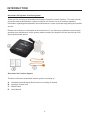
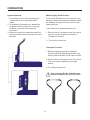
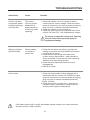
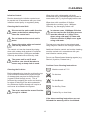
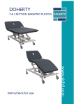
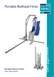
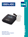
Serenade Lite
Dynamic Cushion System
User Instructions
CONTENTS
Important Notice
Before operating this medical equipment, it is
important to read this manual and understand
the operating instructions and safety
precautions. Failure to do so could result in
injury and/or damage to the product.
If you have any questions, please see contact
information on rear cover.
INTRODUCTION.........................................3
SAFETY PRECAUTIONS.................................4
PRODUCT OVERVIEW....................................5
INSTALLATION................................................6
OPERATION.....................................................8
Control Unit Panel......................................8
Establishing Pressure.................................9
Use of Incontinence Products..................10
Static Mode..............................................10
Removal & Transport Function.................11
Mains Supply Power Failure.....................11
TROUBLESHOOTING...................................12
CLEANING.....................................................13
MAINTENANCE.............................................14
TECHNICAL SPECIFICATION.......................15
WARRANTY INFORMATION.........................21
2
INTRODUCTION
Serenade Lite Dynamic Cushion System
Thank you for choosing a Serenade Lite Analogue Dynamic Cushion System. This user manual
should be read carefully before using the cushion and control unit as it contains important
information regarding safe operation and maintenance in order to provide long lasting and reliable
service.
Please ensure that you understand all the instructions, if you have any questions concerning the
operation and maintenance of the system please contact your supplier who will provide you with
expert professional advice.
Serenade Lite Cushion System
The box contains an assembled cushion system consisting of:
A.
B.
C.
D.
Serenade Lite Alternating Seat Cushion (including air hoses).
Analogue Control Unit
Mains Cable
User Manual
3
SAFETY PRECAUTIONS
In General
Control Unit
Do not use this equipment in the
presence of flammable anaesthetics.
The Serenade Lite cushion is supplied
with an analogue control unit. The
cushion is only compatible with the
analogue system, and is not compatible
with digital control units.
Keep away from sources of heat and
naked flames
Chairs used with the system can vary
greatly depending on the specific
health care setting (i.e. hospitals,
nursing homes, home care etc). It is the
responsibility of the carer to carry out the
necessary risk assessments to ensure
the safety of the patient.
The control unit is tested and CE marked
in line with Medical Device Directive
(93/42/EEC).
Only plug into a mains socket using the
mains cable supplied with the system.
Exposure of the control unit to any liquid
while it is plugged in could result in a
severe electrical hazard.
Do not use on movable chairs /
wheelchairs
Minimise articles between the cushion
surface and patient, so as not to affect
the alternating cell movement.
Only use fuses that have the same
specified rating. Using fuses with higher
ratings could result in damage and/or
injury. (See Technical Specification)
The control unit is a precision electronic
product. Use care when handling or
transporting. Dropping or other sudden
impacts may result in damage to the unit.
Do not open the control unit – risk of
electrical shock. Do not attempt to repair
or service the control unit. Repairs and
service should be conducted by suitably
trained personnel. If the control unit is
not functioning properly, or has been
damaged, unplug the unit and take it
out of service immediately (see contact
information on rear cover for repair and
service information).
Do not place any objects or items, such
as blankets, on or over the control unit.
The mains cable to the control unit should
be correctly positioned to avoid a tripping
hazard and/or damage to the cable. It is
recommended to place the cable to the
rear of the chair, and attach it to a mains
socket by the rear of the chair.
4
PRODUCT OVERVIEW
Alternating Seat Cushion System (see Technical Specification)
Control Unit
The Serenade Lite Dynamic Cushion System is
intended to provide comfort and pressure relief
to patients vulnerable to pressure damage.
It is designed for use on static chairs only.
Ideally, patients allocated to this system will
have some degree of independent mobility or
can be repositioned according to individual
needs.
The control unit provides the air supply to the
cushion.
• It is operated via a control panel with integrated analogue display. A warning light illuminates when low pressure is detected or when power is interrupted. The light will remain illuminated until the fault is rectified.
• Functions on the control panel enable patient comfort level to be adjusted, as well as setting the cushion to static or alternating mode.
The maximum patient weight limit is
110kg (17 Stone).
Dynamic Seat Cushion
If the mains cable becomes detached
the alternation sequence is suspended
and the cushion cells remain inflated
and/or deflated based on the current
cycle. The warning light will illuminate.
This Serenade Lite system includes two layers
of seven cells. The bottom cells and the front
cell in the top layer are static to provide static
support for optimum user comfort, while air
pressure in the other cells is alternated over a
twelve minute cycle. In alternating mode this
provides regular periods of pressure reduction
to aid blood and lymphatic flow to vulnerable
tissue.
5
INSTALLATION
Any damage or missing components should be reported to your supplier as soon as possible.
System Installation
Control Unit Activation
The following describes the procedures for
initial system set up:
a. If possible, remove the existing seat
cushion so that the correct height is preserved.
a. Position the control unit by hanging the hooks over the seat back or place unit on the floor at the rear of, or under the chair with the front facing upwards. Ensure the rear of the unit is not obstructed by carpet, rugs etc. It is advisable to place the unit on a firm surface.
b. Position the cushion on top of the chair seat
section, top cover (printed side) facing upwards
and air hoses at the rear corner of the seat for
control unit positioning.
b. Attach the air connectors to the control unit. Ensure air hoses do not kink.
c. To avoid any risk of damage to the seat
cushion ensure there are no sharp objects
which may come in contact with it.
c. Insert mains cable into the control unit, plug into a mains socket.
Ensure the cushion is in the correct
orientation.
Do not place the seat cushion in a
wide chair without inserting side
buffers to prevent the patient slipping
between the cushion and side arms.
d. Switch on the green power switch to activate the control unit, and turn the dial up to maximum to commence inflation. A light will illuminate indicating the system has activated. Allow up to ten minutes for full inflation.
e. When initial inflation is complete adjust
pressure setting and alternating/static mode
based on patient requirements.
6
INSTALLATION
To attach the air hoses to the control unit:
Align the male air hose fixing (1) with the
female port on the control box (2). Push the air
hose into the port, it should ‘click’ into place.
Follow the above procedure to attach the
female air hose fixing (3) to the male port on
the control box (4).
To remove the air hoses from the control
unit:
The female port on the control box (2) and the
female air hose fixing (3) have a grey section
that can be depressed to release the hose.
Depress the grey section on the female control
box port (2), whilst gently pulling the male air
hose (1) away from the control box. The air
hose will detach from the control box.
Follow the above procedure to remove the
female air hose fixing (3) from the male port on
the control box (4).
7
OPERATION
Control Unit Panel
A - Static Mode Indicator
B - Warning Indicator
C - Power Indicator
D - Power On/Off Switch
E - Pressure Adjusting Dial
F - Alternating/ Static Switch
A Static Mode Indicator
The static indicator light will illuminate when static mode is selected (using the alternating/static
switch). The light will extinguish when the system is manually switched over to alternating
(graphic shows switch in static position).
B Warning Indicator
The warning light will illuminate when a fault condition has arisen in the control unit or cushion.
C Power Indicator
When the control box is connected to mains supply (and turned on using the power on/off
switch) the power indicator will illuminate.
D Power On/Off Switch
Pressing the on/off switch (with the control box connected to mains supply) turns the control
unit on or off.
E Pressure Adjusting Dial
The dial can be rotated clockwise or anticlockwise to increase or decrease the pressure
setting. Pressure setting can be adjusted from soft to firm (30mmHg to 60mmHg).
F Alternating/Static Switch
Selecting alternating mode using the switch cyclically inflates and deflates the cells in
sequence. Selecting static mode fully inflates all cells with no dynamic alternation. This
analogue system will not revert back to alternating mode unless it is manually switched back
over.
8
OPERATION
Seat Cushion Function
Establishing Pressure
Establishing pressure when moving from a
mattress to a cushion
With the patient sitting upright on the cushion,
use the pressure adjusting dial to establish the
best setting for effective support and comfort.
When moving the patient from a mattress
to a cushion, the pressure may need to be
increased to provide added support and to
avoid bottoming out.
Before changing or lowering the pressure,
ensure the system is working effectively.
It is important to return to the original
pressure setting on the mattress
control unit when the patient returns
to the mattress.
Once the system has been set for the patient,
re-check after approximately 20-30 minutes to
ensure the patient is comfortable and that the
unit is functioning correctly.
Wait a minimum of twelve minutes
between pressure adjustment and
patient assessment; it may take a full
cycle for the system to adjust.
A patient assessment must be
performed after seat cushion inflation.
9
OPERATION
Use of Incontinence Products
Static Mode
Incontinence products such as seat covers,
sheets or pads can be used with this system.
However, product performance is likely to
reduce due to the patient experiencing less
pressure relief when using these aids.
The system has the capability to operate as a
static cushion. This function enables nursing
staff to carry out procedures on a static support
surface and/or may be selected if a patient is
finding it difficult to tolerate alternating mode.
(This could occur if, for example, the patient is
in pain or nauseated).
If incontinence products are to be used it is
recommended that regular patient skin checks
are performed to ensure skin integrity is
maintained.
When static is selected all cells inflate at the
pressure at which the cushion is set, thereby
offering a non moving surface. This analogue
system will not return to alternating mode
automatically, it has to be manually switched
back over.
To select static mode press the alternating/
static switch, the static mode indicator will
illuminate. The pressure can be adjusted to
suit using the pressure adjustment dial on the
front of the control unit. The pressure should
be reduced when using the static mode to
check for a patient’s suitability to tolerate a
static surface.
Regular patient skin checks should be
performed to ensure that a static support
surface can be tolerated. Ideally patients
should remain on a static support surface for
no more than two hours without undergoing
a thorough skin check. If the patient cannot
tolerate static mode the system should be
reverted to dynamic therapy by changing the
alternating/static switch to alternating. The
static mode indicator will extinguish.
10
OPERATION
System Removal
Mains Supply Power Failure
1. Turn off the control unit by pressing the power switch, and unplug the mains
cable.
2. To deflate the Serenade Lite, detach the
air pipes from the control box, unzip the
umbilical cord sleeve and open the connector.
3. Place the control unit and mains cable on top of the seat cushion and remove it from the chair.
If it is known that there is to be a power cut in
advance, follow the instructions detailed under
the heading ‘Transport Function’ prior to the
power going off.
In the event of an unplanned power cut:
1. Remove the air connectors from the control unit and connect together (as shown in ‘Transport Function’)
2. Turn off the control unit.
Transport Function
1. Before preparing product for transport, switch mode from alternating to static, and wait for twelve minutes for all cells to inflate.
2. Remove the air connectors from the control unit, and connect together (see image below).
3. Turn off the control unit.
Seat cushion will stay inflated under
normal conditions for up to 12 hours.
11
TROUBLESHOOTING
Alarm/Fault
Cause
Control unit does
not operate; power
indicator light does
not illuminate.
The control
unit may not be
attached to a
power socket, or
a fuse may need
replacing.
Solution
1. Check the control unit is connected to mains
socket with the correct voltage. Check the mains power is switched on (to ensure socket is working plug in a lamp or other fused electrical device).
2. Check the control unit is switched on.
3. Check the mains plug fuse (13A) and then check control unit fuse (1A) – see ‘Maintenance’ section.
Do not try to open the control unit. Opening
the unit could cause personal injury or
equipment damage.
Warning indicator
light illuminates
Power down.
Fault condition
in cushion or
control box.
1. Check the air hoses are intact, ensuring both sealing connectors are firmly fitted to the control
unit and the air hoses.
2. Check all air hoses along the inside of the cushion and air hose sleeve – each should be
firmly connected. Check each air cell is securely attached to its connecting air pipe.
3. Check all cells, pipes and hoses for any air leakage/kinks.
4. Switch on power.
1. Check the mains cable is firmly plugged into a wall socket and the control unit. Check the mains power is switched on (to ensure socket is working plug in a lamp or other fused electrical device). Check 13A fuse.
2. Check the control unit fuse (1A) – fuse can be released using a screwdriver to push and turn – ensure power supply is switched off.
If the above actions fail to rectify the problem please contact your local authorised service provider or Sidhil Limited.
12
CLEANING
Infection Control
Wipe down with a disposable soft cloth
moistened with a mild detergent and diluted in
warm water (40°C), dry thoroughly before use.
Routine cleaning for infection control must
be carried out in accordance with your local
infection control policy or regulatory body.
Wipe down with a solution of Sodium
Hypochlorite or similar (up to 1,000ppm
Chlorine), dry thoroughly before use.
Cleaning the Control Unit
Disconnect the mains cable from the
power socket before attempting to
clean the control unit.
In extreme cases 10,000ppm Chlorine
can be used but the following process
must be adhered to: 1) Wipe cover
down using cold water 2) Clean with
Chlorine solution 3) Wipe cover again
using cold water.
Do not immerse the control unit in
water.
Ensure the mains cable and control
unit are dry before use.
The top cover may also be decontaminated
using Ethylene Oxide or the Draeger method.
The control unit can be cleaned by wiping
down with a damp cloth soaked in a sodium
hypochlorite solution (1000 ppm available
chlorine) and dried with a clean dry cloth.
Additional infection control and routine cleaning
must be carried out in accordance with your
local infection control policy.
Do not use Phenol based cleaning agents (e.g.
Stericol, Hycoline, Clearsol etc.)
The power unit is not IP rated
therefore care should be taken to
ensure only a damp cloth is used.
Cushion Cover Cleaning Instructions.
Cleaning the Cushion
Machine wash at 71°C
Before attempting to clean the cushion the top
cover should be checked for physical signs
of damage that may lead to strike-through
(ingress of fluid through cover). This is
achieved by unzipping the cover and looking
for signs of staining to the white underside.
Any evidence of strike-through will require a
new cover to be fitted to the system.
Do Not Iron
Do Not Bleach
Do Not Dry Clean
The cover must not be reused if strikethrough is evident.
Tumble Dry on Low Heat
If the above washing instructions are not
followed the warranty will be invalidated.
13
MAINTENANCE
Only authorised service personnel or Sidhil service engineers should carry out repairs or service
activities. Failure to do so may result in the product warranty becoming void. The seat cushion
system must be serviced once yearly, as a minimum. Sidhil also recommends that the carer
performs frequent visual and operational inspections. If there are any signs of damage or the
system is not performing as it should withdraw it from service until the system has been repaired
and is fit for use again.
Air Filter Replacement
Fuse Replacement – Control Unit
See service manual for control unit air filter
maintenance and replacement.
1. Switch off the power supply to the control unit.
Good filter maintenance is critical
to maintain an optimal operating
system. Failure to keep the filters
clean will result in system downtime
and increase repair costs. It is
recommended that the air filter be
replaced annually. Replacement air
filters are available; please see contact
information on rear cover.
2. Remove the mains cable from the control unit.
3. Insert a small flat head screwdriver into the groove in the fuse holder, and turn anti-
clockwise (quarter turn).
4. Remove the used fuse from the fuse holder clip and discard.
5. Insert a new fuse into the fuse holder clip. Push fuse holder into the control unit against the force of the spring and turn clockwise with the screwdriver (quarter turn).
14
TECHNICAL SPECIFICATION
Serenade Lite
Control System
Analogue controller
Compatible Control Units
Serenade Lite Only
Cycle Time
12 minutes
Supply Voltage
220-240V, 50Hz
0.2A for Control Unit
Fuse Rating
Mains plug – 13A (x1)
Control unit – 1A (x1)
Power Rating
Standards
Number of Cells
12VA
CE marked in line with Medical Devices Directive (93/42/EEC)
14 cells which includes:
8 static cells (7 in bottom layer, 1 at the front of the top layer)
6 alternating cells
Cell Height
100mm
Alternating Therapy
AB pattern
Maximum Patient Weight
110kg 17 Stone
Cushion Dimensions
Length: 430mm ± 20mm
Width: 430mm ± 20mm
Height: 105mm ± 10mm
Weight: 1.4kgs
Control Unit Dimensions
Height: 275mm
Width: 170mm
Depth: 120mm
Weight: 2kgs
Cell Material
Pure TPU
Base Material
420D PA/TPU
Cover Material
Biocompatible PU/knitted PES, two way stretch, 195 g/m2
Hose Connection
Operating (Storage/Transport)
Environment
Push on air pipes
Air humidity 30% to 75% (10% to 70%)
Ambient temperature 10°C to 40°C (-10°C to 60°C)
15
TECHNICAL SPECIFICATION
Definition of Symbols Used
The following symbols may appear in this manual, on the control unit, or on its accessories. Some
of the symbols represent standards and compliances associated with the control unit and its use.
Caution, consult accompanying documents
Class II equipment
Manufacturer
Serial number
Type B applied part
DISPOSAL: Do not dispose of this product as unsorted municipal waste.
Collection of such waste separately for special treatment is
necessary.
16
TECHNICAL SPECIFICATION
Declaration – electromagnetic emissions- for all ME EQUIPMENT and ME SYSTEMS
Guidance and manufacture’s declaration – electromagnetic emission
The Serenade Lite is intended for use in the electromagnetic environment specified below. The
customer or the user of the Serenade Lite should ensure that it is used in such an environment.
Emission test
Compliance
Electromagnetic
environment – guidance
RF emissions
CISPR 11
Group 1
The Serenade Lite uses RF
energy only for its internal
function. Therefore, its RF
emissions are very low
and are not likely to cause
any interference in nearby
electronic equipment.
RF emission
CISPR 11
Class B
Harmonic emissions
IEC 61000-3-2
Class A
Voltage fluctuations/ flicker
emissions
IEC 61000-3-3
Complies
The Serenade Lite is
suitable for use in all
establishments, including
domestic establishments and
those directly connected to
the public low-voltage power
supply network that supplies
buildings used for domestic
purposes.
17
TECHNICAL SPECIFICATION
Declaration – electromagnetic immunity
Guidance and manufacture’s declaration – electromagnetic immunity
The Serenade Lite is intended for use in the electromagnetic environment specified below.
The customer or the user of the Serenade Lite should ensure that it is used in such an
environment.
Immunity test
IEC 60601 test level
Compliance level
Electromagnetic
environment –
guidance
Electrostatic
discharge (ESD)
IEC 61000-4-2
±6 kV contact
±8 kV air
±6 kV contact
±8 kV air
Floors should be wood,
concrete or ceramic tile.
If floor are covered with
synthetic material, the
relative humidity should
be at least 30%.
Electrical fast
transient/burst
IEC 61000-4-4
±2 kV for power
supply lines
±2kV for power
supply lines
Mains power quality
should be that of a typical
commercial or hospital
environment.
Surge IEC 61000-4-5
± 1 kV line(s) to
line(s)
±1 kV differential
mode
Mains power quality
should be that of a typical
commercial or hospital
environment.
Voltage dips, short
interruptions and
voltage variations on
power supply inpUT
lines
EC 61000-4-11
<5% UT (>95% dip
in UT) for 0.5 cycle
40% UT (60% dip
in UT) for 5 cycles
70% UT (30% dip
in UT) for 25 cycles
<5% UT (>95% dip
in UT) for 5 sec
<5% UT (>95% dip
in UT) for 0.5 cycle
40% UT (60% dip in
UT) for 5 cycles
70% UT (30% dip in
UT) for 25 cycles
<5% UT (>95% dip
in UT) for 5 sec
Mains power quality
should be that of a
typical commercial or
hospital environment. If
the user of the Serenade
Lite requires continued
operation during power
mains interruptions, it is
recommended that the
Serenade Lite is powered
from an uninterruptible
power supply or a
battery.
Power frequency
(50Hz) magnetic field
IEC 61000-4-8
3A/m
3A/m
Power frequency
magnetic fields should
be at levels characteristic
of a typical location in
a typical commercial or
hospital environment.
Note: UT is the a.c. mains voltage prior to application of the test level.
18
TECHNICAL SPECIFICATION
Declaration – electromagnetic immunity – for ME EQUIPMENT and ME SYSTEMS that are
not LIFE-SUPPORTING
Guidance and manufacture’s declaration – electromagnetic immunity
The Serenade Lite is intended for use in the electromagnetic environment specified below. The
customer or the user of the Serenade Lite should ensure that it is used in such an environment.
Immunity
test
IEC 60601
test level
Compliance
level
Electromagnetic environment – guidance
Conducted
RF
IEC 610004-6
3 Vrms
150 kHz to
80 MHz
3 Vrms
Radiated
RF
IEC 610004-3
3 V/m
80 MHz to 2.5
GHz
Portable and mobile RF communications
equipment should be used no closer to any
part of the CT515, including cables, than
the recommended separation distance
calculated from the equation applicable to
the frequency of the transmitter
Recommended separation distance
d = 1.167√P
d = 1.167√P 80 MHz to 800 MHz
d = 2.333√P 800 MHz to 2.5 GHz
Where P is the maximum output power rating
of the transmitter in watts (W) according to
the transmitter manufacturer and d is the
recommended separation distance in meters
(m).
Field strengths from fixed RF transmitters,
as determined by an electromagnetic site
survey,a should be less than the compliance
level in each frequency range.b
Interference may occur in the vicinity of
equipment marked with the following symbol:
3 V/m
NOTE 1 At 80 MHz and 800 MHz, the higher frequency range applies.
NOTE 2 These guidelines may not apply in all situations. Electromagnetic propagation is
affected by absorption and reflection from structures, objects and people.
a. Field strengths from fixed transmitters, such as base stations for radio (cellular/cordless)
telephones and land mobile radios, amateur radio, AM and FM radio broadcast and TV
broadcast cannot be predicted theoretically with accuracy. To assess the electromagnetic
environment due to fixed RF transmitters, an electromagnetic site survey should be considered.
If the measured field strength in the location in which the Serenade Lite is used exceeds the
applicable RF compliance level above, the Serenade Lite should be observed to verify normal
operation. If abnormal performance is observed, additional measures may be necessary, such
as reorienting or relocating the Serenade Lite.
b. Over the frequency range 150 kHz to 80 MHz, field strengths should be less than 3 V/m.
19
TECHNICAL SPECIFICATION
Recommended separation distances between portable and mobile RF communications
equipment and the EQUIPMENT or SYSTEM – for ME EQUIPMENT or ME SYSTEM that are
not LIFE-SUPPORTING
Recommended separation distances between portable and mobile RF communications
equipment and the Serenade Lite Alternating Control Unit
The Serenade Lite is intended for use in an electromagnetic environment in which radiated RF
disturbances are controlled. The customer or the user of the Serenade Lite can help prevent
electromagnetic interference by maintaining a minimum distance between portable and mobile
RF communications equipment (transmitters) and the Serenade Lite as recommended below,
according to the maximum output power of the communications equipment.
Rated maximum
output power of
transmitter (W)
Separation distance according to frequency of transmitter (m)
150 KHz to 80 MHz
d = 1.167√P
80 MHz to 800 MHz
d = 1.167√P
800 MHz to 2.5 GHz
d = 2.333√P
0.01
0.117
0.117
0.233
0.1
0.369
0.369
0.738
1
1.167
1.167
2.333
10
3.689
3.689
7.379
100
11.667
11.667
23.333
For transmitters rated at a maximum output power not listed above, the recommended
separation distance d in meters (m) can be estimated using the equation applicable to the
frequency of the transmitter, where P is the maximum output power rating of the transmitter in
watts (W) according to the transmitter manufacturer.
NOTE 1 At 80 MHz and 800 MHz, the separation distance for the higher frequency range
applies.
NOTE 2 These guidelines may not apply in all situations. Electromagnetic propagation is
affected by absorption and reflection from structures, objects and people.
20
WARRANTY
Sidhil Ltd guarantees this product is free from defects in material and workmanship under normal
use for two (2) years from the date of purchase from Sidhil Ltd and its subsidiary companies or
its authorised dealers. All implied warranties, including but not limited to those implied warranties
of fitness and merchantability, are limited in the total duration of two years from date of purchase.
Proof of purchase must be presented with any claim. Except as provided herein, Sidhil Ltd,
product warranty does not cover damage caused by misuse or abuse, accident, the attachment of
any unauthorised accessory, alteration to the product, or any other conditions whatsoever that are
beyond the control of Sidhil Ltd.
Sidhil Ltd and its subsidiary companies shall have no liability or responsibility to customer or any
other person or entity with respect to any liability, loss or damage caused direct or indirectly by
use or performance of the product or arising out of any breach of this warranty, including but not
limited to any damages resulting from inconvenience, loss of time, property, revenue, or profit or
any indirect, special, incidental or consequential damages, even if Sidhil Ltd or their subsidiary
companies or authorised dealers has been advised of the possibility of such damages. In
the event of a product defect during the warranty period you should contact Sidhil Ltd or their
authorised dealer who will at its option unless otherwise provided by law; a) correct the defect by
product repair without charge for parts and labour b) replace the product with one of the same or
similar design or c) refund the purchase price. All replaced parts and products on which refund is
made become the property of Sidhil Ltd. New or reconditioned parts and products may be used in
the performance of warranty service. Repaired or replaced parts and products are warranted for
the remainder of the original warranty period. You will be charged for repair or replacement of the
product made after the expiration of the warranty period.
This warranty does not cover; a) damage or failure by or attributes to acts of God, abuse,
accident, misuse, improper or abnormal usage, failure to follow instructions, improper installation
or maintenance, alterations, lightning or other incidence of excess voltage or current, b) any
repairs other than those provided by a Sidhil Ltd authorised technician, c) consumables such as
fuses, d) cosmetic damage, e) transportation, shipping or insurance costs or f) costs of product
removal, installation setup service adjustment or re-installation.
This limited two year warranty gives you specific legal rights and you may also have other rights.
Sidhil Ltd cannot be held responsible for any injury or incident which relates to the use of the
Dynamic mattress/cushion range in conjunction with accessories manufactured by companies
other than Sidhil Ltd. All products carry the CE mark in accordance with EC Directive on Medical
Devices (93/42/EEC).
Sidhil has a policy of continual product improvement and reserves the right to amend
specifications covered in this brochure. No part of this brochure may be reproduced without the
written approval of Sidhil Ltd.
21
Tel: 01422 233000 Fax: 01422 233010
Email: [email protected] www.sidhil.com
Sidhil Business Park, Holmfield, Halifax, HX2 9TN
A member of the Siddall & Hilton Ltd. Group of Companies
(93/42/EEC)
Certificate No. FM14550
Serenade Lite, rev1 06/03/13