1
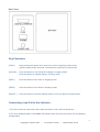
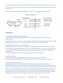
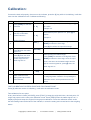
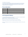
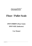
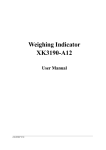
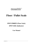
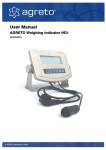
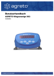
www.scintex.com.au | [email protected]
Model: SHDHS1500
Heavy Duty Horse Scale - Monitor
User’s Manual
1
Copyright (C) Scintex 2014 |
www.scintex.com.au |
[email protected]
NOTE: Please store the scale monitor out of the elements. Do not expose to direct sunlight for long
periods.
Specifications:
1. Model:
2. Accuracy:
3. Sample Rate:
4. Load cell sensitivity:
5. Scale interval:
6. Display:
7. Scoreboard interface (optional):
IE-116LCD weighing indicator
Grade III, n=3000
10 times / second
1.5~3mV / V
1/2/5/10/20/50 options
6 bits LCD,6 state indicating signals
In serial output mode:current loop signal, transmission distance
≤50m
8. Communication interface (optional): RS232C, Baud rate 1200/2400/4800/9600 optional
9. Power supply:
Battery DC6V/4AH
10. Operating temperature/humidity:
0~40oC , ≤90%RH
11. transporting temperature:
-20~50oC
Installation:
Front View
2
Copyright (C) Scintex 2014 |
www.scintex.com.au |
[email protected]
Rear View
Key Functions:
[FUNC ]
Keep pressing this button for 5 seconds or more in weighing mode to enter
operator setting mode; less than 5 seconds and it will enter counting mode.
[ACCUM ]
Press this button to accumulate the weights in weighing mode.
Press this button for sample taking in counting mode.
[TARE ]
Press this button to tare when in weighing mode.
[ZERO ]
Press this button to zero when in weighing mode.
[ON/OFF ]
Press this button to start the indicator when it is off; and press it to power down.
Connecting Load Cell to the Indicator:
1) The 9-pin socket is used to link-up the load cell shown in the Load Cell Schematic.
2) The 4-pin shielded cable is used. Note: the indicator does not have the function for long distance
compensation.
3
Copyright (C) Scintex 2014 |
www.scintex.com.au |
[email protected]
3) The indicator and load cell must have a reliable connection as well as ground for proper operation. If
the indicator is powered on, the user should not insert or withdraw the plug otherwise damage to the load
cells can occur.
4) The sensor and indicator are static sensitive devices; you must adopt anti-static measures.
Load Cell Schematic
Operation:
1) POWER ON AND AUTO ZERO-SETTING
a) The indicator will perform “999999-000000” to self-check when turning on. Then it will enter
weighing mode.
b) When powering on, if a weight is on the scale but is still within the zero set range, the indicator will zero
automatically; if out of range, it is necessary to adjust the zero point, recalibrate or reset.
2) MANUAL ZERO SETTING (AUTOMATICALLY)
a) In weighing mode, if the scales have a positive or negative reading press [Zero] to zero the scales.
b) If the displayed value deviates from the zero point, but is still within the zero-range, pressing the [Zero]
key is available. Otherwise, the [Zero] key is invalid. (In this case, please recalibrate or reset the zero
parameters)
c) Only when stable a stable number is present the zero operation is available.
3) TARE FUNCTION
When the indicator has a stable positive weight, press the [ Tare ] key. The indicator
will deduct the displayed weight value as the tare weight. Then indicator displays net weight as “0 ”.
4) ACCUMULATING FUNCTION
In weighing mode, when the displayed value is positive and stable, press the [Accum] key to
accumulate the present weight and display the accumulated weight, the accumulated annunciator will
be on. Press this key again, it will revert back to the weighing mode and the accumulate annunciator will
be off. The next accumulating operation must be performed after the weight has returned to zero. When
the accumulated weight is displayed, press the [Func] key to clear the accumulated weight in Memory
and press [Accum] to return to weighing mode. If the accumulated weight needs to be checked, please
keep the load on the platform at zero, then press [Accum] to display the accumulated weight.
4
Copyright (C) Scintex 2014 |
www.scintex.com.au |
[email protected]
5) COUNTING FUNCTION
In weighing mode, press [Func] to enter the counting state, it will display “count”, then press [Accum] and
it will display “C00000”, then press [Tare] to move the digit corresponding with the small triangle, the
number corresponding with the small triangle will be increased one by one each time after pressing the
[Zero] key; and it will enter counting function after the sample number inputted and the [Accum] key
pressed. “0” will be displayed and the counting annunciator will be on. Press the [Func] key to return to
weighing mode. After entering counting mode, “count” will be displayed, press [Accum] twice to enter
counting mode directly. The indicator will display according to the last sample. (In this process, if
the ERR4 appears, it means sampling has failed, the indicator will keep the result from the last sample)
6) USER’S FUNCTION SETTING
In weighing mode, keep pressing [F] for 5 seconds or more, it will enter the operator setting mode (mode
P). There are 12 modes from P1 to P12, press the [Accum] key to choose the mode and press [Tare] to
choose the parameter. The description of each parameter is as follows:
P1 - Change Lb to Kg
X=1 (Kg)
X=2 (Lb)
P2 - Automatically Power Off
X=1 (No power off)
X=2 (Power off after 10 mins)
X=3 (Power off after 20 mins)
X=4 (Power off after 30 mins)
P3 - Baud Rate Setting
X=1 (9600)
X=2 (4800)
X=3 (2400)
X=4 (1200)
P4 - RS232 Net / Gross Weight Output Options
X=1 (Net weight output)
X=2 (Gross weight output)
P5 - RS232 Output Mode Option
X=1 (No Transmission)
X=2 (Continuous Transmission)
X=3 (Continuous Transmission when stable)
X=4 (Command mode (Z: zero, T: Tare, R: Transmit weight data once))
X=5 (Current loop output)
X=6 (Keep (printer))
P6 - Back Light Setting
X=1 (No Back Light)
X=2 (Automatic Back Light)
5
Copyright (C) Scintex 2014 |
www.scintex.com.au |
[email protected]
X=3 (Continuous Lighting)
P7 - Zero Tracking Scope
X=1 (0.5e)
X=2 (1.0e)
X=3 (1.5e)
X=4 (2.0e)
X=5 (2.5e)
X=6 (3.0e)
X=7 (5.0e)
P8 - Zero Key Scope
X=1 (2%FS)
X=2 (4%FS)
X=3 (10%FS)
X=4 (20%FS)
P9 - Zero Scope Upon Start Up
X=1 (2%FS)
X=2 (4%FS)
X=3 (10%FS)
X=4 (20%FS)
P10 - Digital Filtering Intensity
X=1 (High)
X=2 (Medium)
X=3 (Low)
P11 - Stable Time
X=1 (High)
X=2 (Medium)
X=3 (Low)
P12 - Stable Extent
X=1 (High)
X=2 (Medium)
X=3 (Low)
6
Copyright (C) Scintex 2014 |
www.scintex.com.au |
[email protected]
Calibration:
Connect the load cell properly, then turn on the indicator, press the [#] key while it is initialising, it will then
enter into the calibration mode. Calibrate as following:
STEP
1
2
OPERATION
DISPLAY
Press [TARE] for selection
[d
of division
Press [TARE] for
selection of DECIMAL
POINT selection
NOTES
Select division optional(1/2/5/10/20/50),press [#]
X]
for confirm
Example: 20
Select decimal point optional: 0~3, press [#] for
[P
X]
confirm
Example:3
Set the full range
[FULL ]
3
4
5
Zero point calibration:
Press [#] when the stable
signal is on
Full range point calibration:
Press [#] when the value
input is the same as the
loaded weight and the
stable signal is on
Press [TARE] for selection of the digit bit; Press
[ZERO] for selection of the digit;
Press [#] for confirm the input of full range
Assure there is no load
[nOLOAD]
While inputting the loaded weight,
Press [TARE] for selection of the digit bit; Press
[AdLOAD]
[ZERO] for selection of the digit; when the input
value is the same as the loaded weight and the
digit bit is at the highest bit, press [#] when the
stable signal is on
6
7
[
End]
Press the calibration
switch under the lead
sealing board at the back
of the indicator
It saves the calibration parameter and back to
the weighing status. Attention: if no pressing the
calibration switch, all the parameters won’t be
saved.
FAST CALIBRATION FOR ZERO POINT AND FULL RANGE POINT
Press [#] while the monitor is initialising, it will enter the calibration mode.
Fast calibration for zero point:
At any time before it shows [nOLOAD], press [FUNC], it keeps the original division, decimal point, full
range and enters into the zero point calibration mode. Press [ZERO] when the stable signal is on, it
displays [End] and keeps the original full range point calibration. Press the calibration switch under
the lead sealing board at the back of the indicator, it saves the setting and reverts back to the weighing
status.
7
Copyright (C) Scintex 2014 |
www.scintex.com.au |
[email protected]
Fast calibration for full range point:
At any time before it shows [AdLOAD], press [ACCU], it keeps the original division, decimal point, full
range, zero point calibration and enters into the full range point calibration mode. When it is finished,
press the calibration switch under the lead sealing board at the back of the indicator, it saves the
setting and reverts back to the weighing status.
Error Indication:
EER 1
The AD value is too small when calibrated.
EER 2
The zero point is out of range when calibrated.
EER 3
The zero point is out or range upon starting
EER 4
The imputed sample number is zero when sampling n counting mode.
EER 5
The imputed weight is zero when full scale calibrated in calibrating mode.
EER 6
The unit weight is less than 0.25e when sampling in counting mode
bAt-lo
Low power
Rechargeable Battery:
Turn on the AC power and the indicator will charge the battery automatically. If not using the indicator for
an extended period of time please remove the battery.
Note: red +ve, black -ve. Incorrect connection will damage the indicator.
Note: The built-in battery should be fully charged before it is used for the first time.
Displaying [LouoL] means there is insufficient voltage and the battery needs charging.
When you use the battery for the first time, you should charge the battery for 20 hours in order to prevent
low voltage.
8
Copyright (C) Scintex 2014 |
www.scintex.com.au |
[email protected]