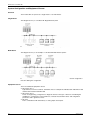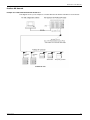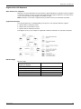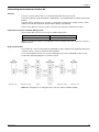
1
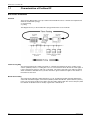
1672611 03/2009 ® TeSys U LULC07 Profibus DP Communication Module Beginner's Guide 1672611 03/2009 www.schneider-electric.com Schneider Electric assumes no responsibility for any errors that may appear in this document. If you have any suggestions for improvements or amendments or have found errors in this publication, please notify us. No part of this document may be reproduced in any form or by any means, electronic or mechanical, including photocopying, without express written permission of Schneider Electric. All pertinent state, regional, and local safety regulations must be observed when installing and using this product. For reasons of safety and to help ensure compliance with documented system data, only the manufacturer should perform repairs to components. When devices are used for applications with technical safety requirements, the relevant instructions must be followed. Failure to use Schneider Electric software or approved software with our hardware products may result in injury, harm, or improper operating results. Failure to observe this information can result in injury or equipment damage. © 2009 Schneider Electric. All rights reserved. 2 1672611 03/2009 Table of Contents Safety Information . . . . . . . . . . . . . . . . . . . . . . . . . . . . . . . . . . . . . . . . . . . . About the Book . . . . . . . . . . . . . . . . . . . . . . . . . . . . . . . . . . . . . . . . . . . . . . . Chapter 1 Architecture of Profibus DP. . . . . . . . . . . . . . . . . . . . . . . . . . . . . . . . . . . . . 5 7 9 1.1 Characteristics of Profibus DP . . . . . . . . . . . . . . . . . . . . . . . . . . . . . . . . . . . . . . . . . . . . . . . . . Bus Access Procedures . . . . . . . . . . . . . . . . . . . . . . . . . . . . . . . . . . . . . . . . . . . . . . . . . . . . . . 1.2 Profibus DP Communication Profile . . . . . . . . . . . . . . . . . . . . . . . . . . . . . . . . . . . . . . . . . . . . . System Configuration and Equipment Classes . . . . . . . . . . . . . . . . . . . . . . . . . . . . . . . . . . . . . Profibus DP Network . . . . . . . . . . . . . . . . . . . . . . . . . . . . . . . . . . . . . . . . . . . . . . . . . . . . . . . . . Types of Communication. . . . . . . . . . . . . . . . . . . . . . . . . . . . . . . . . . . . . . . . . . . . . . . . . . . . . . Device Database . . . . . . . . . . . . . . . . . . . . . . . . . . . . . . . . . . . . . . . . . . . . . . . . . . . . . . . . . . . . Protective Functions . . . . . . . . . . . . . . . . . . . . . . . . . . . . . . . . . . . . . . . . . . . . . . . . . . . . . . . . . 1.3 Topology . . . . . . . . . . . . . . . . . . . . . . . . . . . . . . . . . . . . . . . . . . . . . . . . . . . . . . . . . . . . . . . . . . Transfer Mode . . . . . . . . . . . . . . . . . . . . . . . . . . . . . . . . . . . . . . . . . . . . . . . . . . . . . . . . . . . . . . Segmentation with Repeaters . . . . . . . . . . . . . . . . . . . . . . . . . . . . . . . . . . . . . . . . . . . . . . . . . . 10 10 11 12 13 14 15 16 17 18 19 Chapter 2 Installation of Profibus DP. . . . . . . . . . . . . . . . . . . . . . . . . . . . . . . . . . . . . . 21 Wiring Profibus DP . . . . . . . . . . . . . . . . . . . . . . . . . . . . . . . . . . . . . . . . . . . . . . . . . . . . . . . . . . Constructing the Bus Cable for Profibus DP . . . . . . . . . . . . . . . . . . . . . . . . . . . . . . . . . . . . . . . Trouble Shooting on Profibus DP Installation . . . . . . . . . . . . . . . . . . . . . . . . . . . . . . . . . . . . . . 22 23 24 Chapter 3 EMC Measures . . . . . . . . . . . . . . . . . . . . . . . . . . . . . . . . . . . . . . . . . . . . . . . 25 Grounding and Shielding for Systems with Equipotential Bonding . . . . . . . . . . . . . . . . . . . . . . Grounding and Shielding for Systems without Equipotential Bonding . . . . . . . . . . . . . . . . . . . Capacitive By-Pass Terminal GND 001 . . . . . . . . . . . . . . . . . . . . . . . . . . . . . . . . . . . . . . . . . . Surge Protection for Bus Leads (Lightning Protection) . . . . . . . . . . . . . . . . . . . . . . . . . . . . . . . Static Discharge in Long Profibus DP Cables . . . . . . . . . . . . . . . . . . . . . . . . . . . . . . . . . . . . . . 26 27 28 29 31 Index . . . . . . . . . . . . . . . . . . . . . . . . . . . . . . . . . . . . . . . . . . . . . . . . . . . . . . . 33 1672611 03/2009 3 4 1672611 03/2009 Safety Information § Important Information NOTICE Read these instructions carefully, and look at the equipment to become familiar with the device before trying to install, operate, or maintain it. The following special messages may appear throughout this documentation or on the equipment to warn of potential hazards or to call attention to information that clarifies or simplifies a procedure. PLEASE NOTE Electrical equipment should be installed, operated, serviced, and maintained only by qualified personnel. No responsibility is assumed by Schneider Electric for any consequences arising out of the use of this material. A qualified person is one who has skills and knowledge related to the construction and operation of electrical equipment and the installation, and has received safety training to recognize and avoid the hazards involved. 1672611 03/2009 5 6 1672611 03/2009 About the Book At a Glance Document Scope This documentation comprises general information on the architecture and the installation of Profibus DP and the EMC measures to be taken. Validity Note This manual is valid for LULC07 V1.2 and later versions. LULC07 can be used with TeSys U power bases (LUB/2B, LUS/2S) only. LULC07 is not compatible with the TeSys U controller bases (LUTM). Related Documents Title of Documentation Reference Number LULC07 Profibus DP Module - Instruction Sheet 1639544 LU9GC7 Profibus DP Tap Module - Instruction Sheet 1639559 LU9AD7 Profibus DP Connector - Instruction Sheet 1639560 LULC07 Profibus DP Communication Module User's Manual 1672610 LULC07 Profibus DP Module - Acyclic Data Read/Write with Siemens, Application Note 1672612 TeSys U Communication Variables - User’s Manual 1744082 LU•B/LU•S• TeSys U Starters - Instruction Sheet 1629984 LUCM/LUCMT Multifunction Control Units - User’s Manual 1743237 LUCM/LUCMT/LUCBT/LUCDT Control Units - Instruction Sheet AAV40504 LUCA/LUCB/LUCC/LUCD Control Units - Instruction Sheet AAV40503 Electromagnetic Compatibility - Practical Installation Guidelines DEG999 You can download these technical publications and other technical information from our website at www.schneider-electric.com. Product Related Information Up-to-date information about Profibus DP is available from the Profibus Website http://www.profibus.com as well as from the Profibus user organization: Profibus Nutzerorganisation e.V., Haid- und Neu-Straße 7, D-76131 Karlsruhe, Germany, or from the Profibus user organisation in your country. User Comments We welcome your comments about this document. You can reach us by e-mail at [email protected]. 1672611 03/2009 7 8 1672611 03/2009 Architecture of Profibus DP 1672611 03/2009 Architecture of Profibus DP 1 Overview This chapter comprises basic information on the Profibus DP architecture. What's in this Chapter? This chapter contains the following sections: Section 1672611 03/2009 Topic Page 1.1 Characteristics of Profibus DP 10 1.2 Profibus DP Communication Profile 11 1.3 Topology 17 9 Architecture of Profibus DP 1.1 Characteristics of Profibus DP Bus Access Procedures Overview There are two different bus access procedures which handle the various communication requirements within the Profibus DP topology: token passing polling This diagram shows you the Profibus DP topology with both bus access methods. Token Passing Ring The token passing ring procedure is the basis for communication between the more complex, active stations (=Master). This is for creating bus access for several stations which all have the same rights. A token is passed from station to station in a logical ring. The token is passed to each and every station within a maximum, definable token cycle time. A station is given transmission rights for the duration of time that it has the token. Master-Slave Polling The master-slave polling procedure guarantees a cyclic, real-time based data exchange between the station with transmission rights, active station (=Master) and its subordinates, passive stations (=slaves). In this case, the master is able to pass data to the slave and/or request data. The services in layer 2 (fieldbus data link in ISO-OSI reference model) organize this communication. 10 1672611 03/2009 Architecture of Profibus DP 1.2 Profibus DP Communication Profile Overview This chapter contains information on the Profibus DP communication profile. What's in this Section? This section contains the following topics: Topic 1672611 03/2009 Page System Configuration and Equipment Classes 12 Profibus DP Network 13 Types of Communication 14 Device Database 15 Protective Functions 16 11 Architecture of Profibus DP System Configuration and Equipment Classes Overview The Profibus DP can operate as a single master or as multi-master. Single Master This diagram shows you a Profibus DP Single Master System: NOTE: The shortest bus cycle time is achieved in single master operation. Multi-Master This diagram shows you an example of a Profibus DP Multi-master System: NOTE: Communication with a slave is reserved only to the DPM1 Master which has been assigned for this slave during the configuration. Equipment Classes There are 3 different equipment classes: 12 DP master class 1 Typical devices are PLCs and PCs. Schneider offers for example the TSX Quantum 140 CRP 811 00 and the TSX Premium TSX PBY 100. DP master class 2 These are engineering, configuration or diagnostic devices. This type of device is used during the installation to configure the connected devices, evaluate measurement values and configuration parameters and to get device states. DP slave This is a field device with either binary or analog inputs and outputs. 1672611 03/2009 Architecture of Profibus DP Profibus DP Network Example of a Profibus DP Network with the CRP 811 This diagram shows you an example of a Profibus DP network with the 140 CRP 811 as the master. 1672611 03/2009 13 Architecture of Profibus DP Types of Communication Overview Besides logical point to point data transfers, the Profibus DP protocol can also handle the following types of communication: broadcast communication An active node sends an unacknowledged message to all other nodes (master and slaves). multicast communication (control instructions) An active node sends an unacknowledged message to a group of nodes (master and slaves). Master-Slave Communication Phases The communication between the DPM1 and the DP slaves is split up into the following phases: parameterization and configuration phase usable data transfer phase Master-Slave Communication Establishment Before a DP slave can be integrated into the usable data transfer phase, the DPM1 checks for whether the planned set configuration (see Notes) matches the real device configuration in the parameterization and configuration phase. A device identification test is run for every slave checking whether the device is actually there, it is the right type of device, the address which is set on the device matches the station address on the bus, the formats, telegram length information and bus parameters are correct and the number of configured inputs and outputs is correct. NOTE: The set configuration is created with a configurator based on the General Specification of Device (GSD file), for all slaves. Diagnostic on Profibus DP As a part of establishing the communication the DPM1 master is requesting diagnostic frames from the slave to get information about the status of the slave. In this phase only the first manufacturer independent bytes are of interest for the master. During communication diagnostic frames are also requested by the DMP1 master but the original trigger is coming from the slave. Each slave checks the application specific part of the diagnostic frame for changes. In case a change is detected, the data record exchanged cyclically with the master gets an indication added new diagnostic data. The DPM1 master will react and request the diagnostic frame afterwards. Electronic Device Description The TeSys U system is described by a GS*-file. This file will be used by any Profibus DP configuration tool to get information about the device. The file for LULC07 is called TELE094C.GS*. The *-mark will be replaced for example by G for German, E for English, F for French and so on (D for Default). WARNING UNINTENDED EQUIPMENT OPERATION Do not modify the GS*-file in any way. Modifying the GS*-file can cause unpredictable behaviour of the devices. Failure to follow these instructions can result in death, serious injury, or equipment damage. NOTE: If the GS*-file is modified in any way, the warranty of Schneider Electric will expire immediately. 14 1672611 03/2009 Architecture of Profibus DP Device Database Device Properties In Profibus DP, the performance features of the devices are documented by the manufacturer and provided as an equipment data sheet and a device database file, made available to the user. The structure, contents and coding for this device database are standardized. They enable you to configure comfortably any number of DP slaves using various manufacturers' configuration equipment. The Profibus user organization archives this information by manufacturer and will provide information about the device database upon request. Device Identification The identification number enables a DP master to identify the types of devices that are connected without any significant protocol overhead. The master compares the Ident-number of the connected DP device with the Ident-number of the defined configuration data. Application data transmission begins only when the proper device types with the correct station addresses are connected to the bus. In this way, a relatively high security from configuration errors is achieved. Manufacturers must register an identification number for every DP slave and every DPM1 master with the Profibus user organization. The Profibus user organization coordinates these identification numbers along with the device data. More information can be obtained through the PNO (Profibus user organization). 1672611 03/2009 15 Architecture of Profibus DP Protective Functions Overview Profibus DP has protective functions that guard against incorrect parameterization or transfer equipment break-down. These monitoring mechanisms are real-time monitors with the DP master and DP slaves. The length of the monitoring interval is defined during the configuration of the system. Data Control Time The DPM1 monitors the usable data transfer of every DP slave with a separate Data Control Time (DCT). The monitor responds if an improper usable data transfer occurs within the DCT. DP Slave Watchdog Monitor The DP slave runs a watchdog monitor for recognizing errors from the DP master or the transmission path. If no data traffic with the assigned DP master is found within a watchdog interval then the DP slave switches the outputs to a defined shut-down value. NOTE: The DCT and the watchdog times are bus parameters which are defined during the configuration by the configurator and depend on the number of slaves. Access Protection There is also access protection for the inputs and outputs of the DP slave during operation in multi-master systems so that direct access only occurs from the master with the assigned rights. 16 1672611 03/2009 Architecture of Profibus DP 1.3 Topology Foreword This chapter contains information on the Profibus DP topology. What's in this Section? This section contains the following topics: Topic 1672611 03/2009 Page Transfer Mode 18 Segmentation with Repeaters 19 17 Architecture of Profibus DP Transfer Mode Overview Since it is impossible to satisfy all requirements with one method of transfer, there are 3 different methods available for Profibus DP. RS-485 RS-485 is a method of transfer for universal applications in manufacturing technology. It is the most widely used form of transfer in Profibus DP. It guarantees high speed with simple and inexpensive cabling. Twisted pair copper cable is used as the conductor. Speeds from 9.6 kbit/sec up to 12 Mbit/sec can be defined. This is defined uniformly for all devices during the configuration of the system and is based on the maximum bus cable lengths. Network topology is a linear bus with active bus terminations on both ends. The TeSys U on Profibus provides a RS-485 interface. IEC-1158-2 IEC-1158-2 is a method of transfer which is used in process automation with the Profibus DP PA physical profile. This bit synchronous transfer method is based on two-wire technology and is noted for its inherent safety and bus feed. It can therefore be used in Ex-applications as well. Network topology is a tree or linear structure or can be a combination of both. Fiber Optic Cable Fiber optic cable is used for applications where the environment is unstable (heavy disturbance), for potential isolation or for increasing the range at high transmission speeds. The network topology of Profibus DP fiber optics segments is either a star or ring structure. For connecting a fiber optic segment to an RS-485 transmission path, fiber optic couplers are available. When increasing distances however, note that no more nodes may be added to the fiber optic segment besides the couplers. 18 1672611 03/2009 Architecture of Profibus DP Segmentation with Repeaters When Should I Use a Repeater? Repeaters can be integrated wherever the maximum cable length will be exceeded in a network segment or where the number of nodes exceeds the allowed number per segment. Repeaters are used in these cases to increase the bus cable length or the number of nodes. NOTE: Repeaters on the ends of segments must, just like the slaves, be terminated respectfully. Segmentation Example The following methods are used depending on the position of the repeater within the segment: repeater with no termination resistor repeater with one termination resistor repeater with two termination resistors This diagram shows you an example of segmentation with bus terminations for repeaters and slaves. Effective Range Effective range 1672611 03/2009 Max. Cable Length without repeater / with 3 repeaters per Segment Baud Rates (for 12 Mbit/sec Cable) 800/ 3200 m (2,624 / 10,498 ft) 9.6/19.2/45.5/93.75 kbit/sec 650 / 2,600 m (2,132 / 8,530 ft) 187.5 kbit/sec 300 / 1,200 m (984 / 3,936 ft) 500 kbit/sec 160 / 640 m (524 / 2,099 ft) 1.5 Mbit/sec 80 / 320 m (262 / 1,049 ft) 3/6/12 Mbit/sec 19 Architecture of Profibus DP 20 1672611 03/2009 Installation 1672611 03/2009 Installation of Profibus DP 2 Overview This chapter comprises information concerning the installation and first operational steps. WARNING UNINTENDED EQUIPMENT OPERATION These devices must be installed, configured and used by qualified staff only. You must follow all current instructions, standards and regulations. Check the function settings before starting the motor. Do not downgrade or modify these devices. Incorrect configuration can cause unpredictable behaviour of the devices. Failure to follow these instructions can result in death, serious injury, or equipment damage. What's in this Chapter? This chapter contains the following topics: Topic Wiring Profibus DP 1672611 03/2009 Page 22 Constructing the Bus Cable for Profibus DP 23 Trouble Shooting on Profibus DP Installation 24 21 Installation Wiring Profibus DP Guidelines for Bus Segment Installation The following guidelines apply for wiring bus segments: Type "A" bus cable which complies with Profibus DP standards is to be used. The bus cable may not be twisted, pinched or stretched. A bus segment must be fitted with a termination resistor on both ends. The corresponding slave must be live at all times so that the termination resistor is effective however. Bus nodes that do not terminate a segment can be separated from the bus without interrupting regular data traffic. Branch lines are not allowed. Wiring in Buildings In Cabinets Cable locations play a major role in the resistance to interference. Therefore, the following guidelines are applied: Data lines must be separated from all AC and DC power lines 60 V. A minimum spacing of 20 cm (7.9 in) is to be kept between data lines and power lines. AC and DC feed wires > 60 V and 230 V must be run separately from AC and DC power feeds > 230 V Separately means that the cables are in different cable bundles and ducts. PG screws with integrated grounding are not allowed. Cabinet lighting must be done with EMC safe lights and wiring. Outside of Cabinets Cables must be run in metal cable ducting (lines, cable troughs, ducts or tubing) wherever possible. Only wires of < 60 V or shielded < 230 V may be run in common cable ducts. Dividers in metal cable ducts may be used as long as the minimum spacing of 20 cm (7.9 in) is kept between wires. Profibus DP data lines must be run separately in metal cable ducts. Wiring Outside of Buildings Generally, the same rules apply for running lines outside of buildings as within. However, the following applies to bus cable: 22 Run in a suitable plastic tubing. When burying cables, only cable that is specifically designed for this purpose may be used. Pay special attention to the permitted temperatures. When running cables between buildings, use surge protectors for bus lines (lightning protection). For baud rates over 500 kBaud, fiber optics cable is recommended. 1672611 03/2009 Installation Constructing the Bus Cable for Profibus DP Overview You must construct the bus cable for connecting Profibus DP devices by yourself. A special Profibus DP cable (twisted pair) is required here. The standard cable is available at Schneider Electric. A special cable is required for the connection of the LULC07 communication module (see list of Trunk Cables in the LULC07 Profibus DP Communication Module, User Manual). There are also different connectors for the connection of the LULC07 communication module. Connection Accessories for RS485 Wiring System List of Profibus DP connection accessories for RS485 wiring system. Type of Master Part Number Customized Bus Connector LU9AD7 for the communication module NOTE: For detailed informations on installing the connectors please refer to the respective connector´s instruction sheet. Begin and End of Bus The Profibus DP connector with termination (490 NAD 911 03) is required at the beginning and the end of the bus. These connectors emulate the line impedance. It is recommended that at least one connector with diagnostics interface (490 NAD 911 05) is used. Profibus DP cable wiring diagram for a TeSys U system NOTE: Bus testing device for testing the status of the bus cable is available (BT200...) 1672611 03/2009 23 Installation Trouble Shooting on Profibus DP Installation Finding the Source of the Error When an error occurs, check the configured hardware against the following list of error sources: Compare configured module types with the existing modules. Examine the voltage supply to all modules. Compare configured addresses with the addresses specified on the bus adapter. Examine the parameters for complex (analog) modules. Check EMC and equipotential bonding precautions. Test all cabling and connections: bus connector screws proper cable location termination resistors proper connectors (for 12 MBaud, special connectors with built-in restrictors must be used) 24 Check general contact problems with connections. 1672611 03/2009 EMC Measures 1672611 03/2009 EMC Measures 3 Overview This chapter comprises information concerning the EMC measures with Profibus DP communication. What's in this Chapter? This chapter contains the following topics: Topic 1672611 03/2009 Page Grounding and Shielding for Systems with Equipotential Bonding 26 Grounding and Shielding for Systems without Equipotential Bonding 27 Capacitive By-Pass Terminal GND 001 28 Surge Protection for Bus Leads (Lightning Protection) 29 Static Discharge in Long Profibus DP Cables 31 25 EMC Measures Grounding and Shielding for Systems with Equipotential Bonding Central Shielding Measures Each cable shield should be galvanically earth grounded using FE/PE grounding clamps immediately after the cable has been connected to the cabinet. This example indicates the shielding connection from the Profibus cable to the FE/PE rail. 1 2 3 4 PE/FE rail FE Profibus cable Clamps, provide contact with the cable NOTE: An equalization current can flow across a shield connected at both ends because of fluctuations in ground potential. To prevent this, it is imperative that there is potential equalization between all the attached installation components and devices. This example indicates the system components and devices in a system with equipotential bonding. 1 2 3 4 5 6 7 26 Main switching cabinet Substation "1" Substation "n" PLC with DP master FE/PE rail Profibus DP cable Equipotential bonding, conductor > 16 mm2 (AWG 6) 1672611 03/2009 EMC Measures Grounding and Shielding for Systems without Equipotential Bonding Principle NOTE: It is recommended to ground and shield systems using equipotential bonding. If this is not possible because of system or construction specific reasons then use distributed grounding with a capacitive coupling of high frequency interference signals. Overview This representation shows distributed grounding with capacitive coupling: 1 2 3 4 5 6 7 Main switching cabinet Substation "1" Substation "n" Quantum with DP master FE/PE rail Profibus DP cable Capacitive by-pass terminal, GND 001 Distributed Grounding with Capacitive Coupling This table shows you the steps in setting up distributed grounding with capacitive coupling. Step 1672611 03/2009 Action 1 Galvanically ground the shielding (only) to the end of the bus cable and with as much surface area as possible to the central cabinet. 2 Run the bus cable from there to the last bus node, without any other ground connections. 3 Shield all bus nodes "capacitive only". To do this use e.g. the GND 001 terminal connection. 4 Refer to the connection example and the details concerning shielding in the instructions for the corresponding device. Comments This provides a discharge route for high frequency interferences. Note: A transient current cannot flow without a galvanic connection. 27 EMC Measures Capacitive By-Pass Terminal GND 001 Overview Distributed grounding with capacitive by-passing is used in systems without equipotential bonding. Mount the Schneider by-pass terminal (GND 001) as shown in the following representations. Connection Example This example shows the connection from the Profibus DP cable to the by-pass terminal. 1 2 3 4 5 GND 001 Shielding Connection to rail Profibus DP cable entering switching cabinet Profibus DP cable exiting switching cabinet Making Shielding Connections This example shows the shielding connection with the Profibus DP cable. 1 Copper shield foil (included) NOTE: The by-pass for the bus ends is to be prepared on 1 cable only 28 1672611 03/2009 EMC Measures Surge Protection for Bus Leads (Lightning Protection) Surge Protection for Bus Leads Up to 12 Mbps Signals To protect transmission systems from extraneous surges (lightning), the Profibus DP lead should be equipped with suitable surge protection equipment once it extends outside a building. The nominal discharge current should, in this case, be at least 5 kA. The following lightning arrestors e.g. type CT MD/HF5 and type CT B110 from Dehn und Söhne GmbH & Co KG may be used. Addresses and order numbers for these devices can be found under Surge Protection Equipment). For adequate protection of a Profibus DP cable, two sets of protection equipment are required for each building. The first set of protection devices (type B110), located where the cable enters the building, works as a lightning conductor, the second (type MD/HF5), located near the first device, works as a surge protection device. Connection Rules for Protection Devices Before connection of the protection devices please observe the following rules: Install a functional ground (equipotential bonding rail). Install the protection equipment near the functional ground, to keep surge current path as short as possible. Keep the lead to the functional ground as short as possible. (min. 6 mm2) The maximum lead length depends on the transfer rate. At transfer rates up to 500 kBd you can configure a maximum of 4 outdoor segments with 8 pairs of protection devices (CT B110 and CT MD/HF5). At transfer rates of 1 MBd or higher, you may only configure 1 outdoor segment with 2 pairs of protection devices. 1672611 03/2009 Do not confuse the IN and OUT ends of the lightning arrestor (IN = outdoor end) Make certain that you ground the shielding of the Profibus DP lead protective devices according to the type of lightning arrestor (CT B110 or CT MD/HF5) that is used. 29 EMC Measures Protection Device Connection Plan Protection device connection plan 1 2 3 4 5 6 7 CT MD/HF 5 CT B110 Switching cabinet Bus node Structure 1 Structure 2 Outdoor Type and number of lightning conductors made by the firm Dehn und Söhne GmbH &Co KG suitable for a Profibus DP cable: No. Model Number per Group 1 CT MD/HF 5 2 2 CT B110 2 NOTE: Information about assembly and connection of the cables can be found in the relevant installation instructions that come with lightning arrestor. Shield Grounding with Protection Devices Direct or indirect shield grounding are offered by the protection devices. An indirect grounding occurs using gas conductors. In both cases EMC spring terminals grasp the input and output sides of the cable shield. NOTE: It is recommended to use direct shield grounding, when the system permits it. Types of shield grounding assignment Type of Grounding Technique Direct Shield Grounding Connect the shield of the incoming cable to the IN terminal, and that of the outgoing cable to the OUT terminal. The shields are now galvanically connected with PE. Indirect Shield Grounding Using Gas Conductors Connection of the shield as described for direct shield grounding. Insert the gas-type surge protector in the rack beneath the cabinet connection terminals on the input side. NOTE: Further information about grounding and shield grounding can be found in the relevant installation instructions that come with the lightning arrestor. 30 1672611 03/2009 EMC Measures Static Discharge in Long Profibus DP Cables Static Discharge Very long bus cables, which have been laid but not yet connected, are discharged as follows: Step Action 1 Select the Profibus DP connector closest to the FE/PE grounding clamp. 2 Touch the metal of the connector housing to the cabinet's FE/PE grounding clamp to discharge any static electricity. 3 Connect the bus connector to the device. 4 Discharge the other Profibus DP cable connectors as described in steps 2 and 3. Notes NOTE: During mounting, the metal part of the Profibus DP connector is connected internally to the cable shield. When the bus cable connector is inserted into the module’s Profibus DP port, a short connection between the shield and the FE/PE is created automatically, except for the TeSys U system. 1672611 03/2009 31 EMC Measures 32 1672611 03/2009 Index 1672611 03/2009 B AC Index A F access protection, 16 access to bus procedures, 10 accessories, 23 architecture of Profibus DP, 9 fiber optic cable, 18 first steps and installation Profibus DP, 21 B bus access procedures, 10 bus cable constructing, 23 bus segment installation, 22 by-pass terminal GND 001 capacitive, 28 C cable, fiber optic, 18 cables static discharge, 31 capacitive by-pass terminal GND 001, 28 characteristics of Profibus DP, 10 communication profile Profibus DP, 11 communication types, 14 connection accessories, 23 connection plan for protection devices, 30 connection rules for protection devices, 29 connections shielding, 28 constructing the bus cable, 23 D data control time, 16 database, 15 device database, 15 identification, 15 properties, 15 device database, 15 device description, electronic, 14 distributed grounding, 27 G grounding and shielding with equipotential bonding, 26 without equipotential bonding, 27 GS*-file, 14 I IEC-1158-2, 18 installation Profibus DP, 21 installation, wiring Profibus DP, 22 L lightning protection, 29 M master-slave establishment, 14 phases, 14 master-slave polling, 10 multi-master, 12 N network components Profibus DP, 13 E effective range, 19 electronic device description, 14 EMC measures Profibus DP, 25 equipment classes, 12 1672611 03/2009 33 Index P Profibus DP architecture, 9 capacitive by-pass terminal GND 001, 28 characteristics, 10 commissioning, 21 EMC measures, 25 grounding and shielding with equipotential bonding, 26 grounding and shielding without equipotential bonding, 27 installation, 21 installation, constructing the bus cable, 23 installation, trouble shooting, 24 installation, wiring, 22 lightning protection, 29 network components, 13 static discharge in long cables, 31 surge protection for bus leads, 29 topology, 17 Profibus DP communication profile, 11 protection devices connection plan, 30 connection rules, 29 shield grounding, 30 protective functions, 16 wiring, installation Profibus DP, 22 R range, effective, 19 repeaters segmentation with, 19 RS-485, 18 S segmentation with repeaters, 19 shield grounding for protection devices, 30 shielding connections, 28 shielding measures, 26 single master, 12 static discharge in long cables Profibus DP, 31 surge protection, 29 surge protection for bus leads, 29 system configuration and equipment classes, 12 T token passing ring, 10 topology, 17 Profibus DP, 17 transfer mode, 18 trouble shooting installation Profibus DP, 24 W watchdog monitor, 16 wiring in buildings, 22 outside of buildings, 22 wiring diagram Profibus DP, 23 34 1672611 03/2009