1
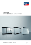
Central Inverter
SUNNY CENTRAL 500HE-US/CA
Maintenance Manual
SC500HEUS-eng-WH-IUS120411 | 98-4103011 | Version 1.1
CA
US
SMA America, LLC
Legal Restrictions
Copyright © 2012 SMA America, LLC. All rights reserved.
No part of this document may be reproduced, stored in a retrieval system, or transmitted, in any form
or by any means, electronic, mechanical, photographic, magnetic or otherwise, without the prior
written permission of SMA America, LLC.
Neither SMA America, LLC nor SMA Solar Technology Canada Inc. makes representations, express
or implied, with respect to this documentation or any of the equipment and/or software it may
describe, including (with no limitation) any implied warranties of utility, merchantability, or fitness for
any particular purpose. All such warranties are expressly disclaimed. Neither SMA America, LLC nor
its distributors or dealers nor SMA Solar Technology Canada Inc. nor its distributors or dealers shall
be liable for any indirect, incidental, or consequential damages under any circumstances.
(The exclusion of implied warranties may not apply in all cases under some statutes, and thus the
above exclusion may not apply.)
Specifications are subject to change without notice. Every attempt has been made to make this
document complete, accurate and up-to-date. Readers are cautioned, however, that
SMA America, LLC and SMA Solar Technology Canada Inc. reserve the right to make changes
without notice and shall not be responsible for any damages, including indirect, incidental or
consequential damages, caused by reliance on the material presented, including, but not limited to,
omissions, typographical errors, arithmetical errors or listing errors in the content material.
All trademarks are recognized even if these are not marked separately. Missing designations do not
mean that a product or brand is not a registered trademark.
The Bluetooth® word mark and logos are registered trademarks owned by Bluetooth SIG, Inc. and
any use of such marks by SMA America, LLC and SMA Solar Technology Canada Inc. is under
license.
SMA America, LLC
3801 N. Havana Street
Denver, CO 80239 U.S.A.
SMA Solar Technology Canada Inc.
2425 Matheson Blvd. E
8th Floor
Mississauga, ON L4W 5K5
Canada
Maintenance Manual
SC500HEUS-eng-WH-IUS120411
3
Important Safety Instructions
SMA America, LLC
IMPORTANT SAFETY INSTRUCTIONS
SAVE THESE INSTRUCTIONS
This manual contains important instructions for the following products:
• Sunny Central 500HE-US/CA
This manual must be followed during installation and maintenance.
The product is designed and tested according to international safety requirements, but as with all
electrical and electronic equipment, certain precautions must be observed when installing and/or
operating the product. To reduce the risk of personal injury and to ensure the safe installation and
operation of the product, you must carefully read and follow all instructions, cautions and warnings
in this manual.
Warnings in this document
A warning describes a hazard to equipment or personnel. It calls attention to a procedure or practice,
which, if not correctly performed or adhered to, could result in damage to or destruction of part or all
of the SMA equipment and/or other equipment connected to the SMA equipment or personal injury.
Symbol
4
Description
%"/(&3
DANGER indicates a hazardous situation which, if not avoided, will result in
death or serious injury.
8"3/*/(
WARNING indicates a hazardous situation which, if not avoided, could result
in death or serious injury.
$"65*0/
CAUTION indicates a hazardous situation which, if not avoided, could result
in minor or moderate injury.
/05*$&
NOTICE is used to address practices not related to personal injury.
SC500HEUS-eng-WH-IUS120411
Maintenance Manual
SMA America, LLC
Important Safety Instructions
Other Symbols in this document
In addition to the safety and hazard symbols described on the previous pages, the following symbol
is also used in this manual:
Symbole
Description
Indicates information that is important for a specific topic or objective, but is not
safety-relevant.
☐
Indicates a requirement for meeting a specific goal.
☑
Desired result
✖
A problem that could occur
Markings on this product
The following symbols are used as product markings with the following meanings.
Symbol
Description
Warning regarding dangerous voltage
The product works with high voltages. All work on the product must only be
performed as described in the documentation of the product.
Electric arc hazards
The product has large electrical potential differences between its conductors. Arc
flashes can occur through air when high-voltage current flows. Do not work on the
product during operation.
Beware of hot surface
The product can become hot during operation. Do not touch the product during
operation.
Observe the operating instructions
Read the documentation of the product before working on it. Follow all safety
precautions and instructions as described in the documentation.
Evaluated to the requirements of the Underwriters Laboratories Standard for
Safety for Inverters, Converters, Controllers and Interconnection System
Equipment for Use With Distributed Energy Resources, UL 1741.
The inverter has been additionally evaluated by Underwriters Laboratories to
CAN/CSA C22.2 No. 107.1-1, "General Use Power Supplies."
Maintenance Manual
SC500HEUS-eng-WH-IUS120411
5
General Warnings
SMA America, LLC
General Warnings
8"3/*/(
General Warnings
All electrical installations must be done in accordance with the local and National Electrical Code®
ANSI/NFPA 70 or the Canadian Electrical Code® CSA C22.1. This document does not and is not
intended to replace any local, state, provincial, federal or national laws, regulations or codes
applicable to the installation and use of the product, including without limitation applicable
electrical safety codes. All installations must conform with the laws, regulations, codes and
standards applicable in the jurisdiction of installation. SMA assumes no responsibility for the
compliance or non-compliance with such laws or codes in connection with the installation of the
product.
Before installing or using the product, read all of the instructions, cautions, and warnings in this
manual.
Before connecting the product to the electrical utility grid, contact the local utility company. This
connection must be made only by qualified personnel.
Wiring of the product must be made by qualified personnel only.
6
SC500HEUS-eng-WH-IUS120411
Maintenance Manual
SMA America, LLC
Table of Contents
Table of Contents
1
Notes on this Document. . . . . . . . . . . . . . . . . . . . . . . . . . . . 9
2
2.1
2.2
2.3
2.4
Safety . . . . . . . . . . . . . . . . . . . . . . . . . . . . . . . . . . . . . . . . . 10
Intended Use. . . . . . . . . . . . . . . . . . . . . . . . . . . . . . . . . . . . . . . 10
Target Audience Skills. . . . . . . . . . . . . . . . . . . . . . . . . . . . . . . . 10
Personal Protective Equipment . . . . . . . . . . . . . . . . . . . . . . . . . 11
Safety Precautions. . . . . . . . . . . . . . . . . . . . . . . . . . . . . . . . . . . 11
3
3.1
3.2
Product Description . . . . . . . . . . . . . . . . . . . . . . . . . . . . . . 15
Design of the Inverter . . . . . . . . . . . . . . . . . . . . . . . . . . . . . . . . 15
User Interface . . . . . . . . . . . . . . . . . . . . . . . . . . . . . . . . . . . . . . 15
4
4.1
4.2
Maintenance. . . . . . . . . . . . . . . . . . . . . . . . . . . . . . . . . . . . 16
Maintenance Intervals . . . . . . . . . . . . . . . . . . . . . . . . . . . . . . . 16
Preparing for Maintenance. . . . . . . . . . . . . . . . . . . . . . . . . . . . 17
4.2.1
Identifying the Inverter. . . . . . . . . . . . . . . . . . . . . . . . . . . . . . . . . . . . . . . . . . 17
4.2.2
Reading Error Messages. . . . . . . . . . . . . . . . . . . . . . . . . . . . . . . . . . . . . . . . 18
4.2.3
Performing Visual Inspection . . . . . . . . . . . . . . . . . . . . . . . . . . . . . . . . . . . . . 18
4.3
Maintenance under Dead Conditions. . . . . . . . . . . . . . . . . . . . 19
4.3.1
4.3.2
Disconnecting the Inverter . . . . . . . . . . . . . . . . . . . . . . . . . . . . . . . . . . . . . . . 19
Checking Safety Messages. . . . . . . . . . . . . . . . . . . . . . . . . . . . . . . . . . . . . . 22
4.3.3
Disassembling the Panels . . . . . . . . . . . . . . . . . . . . . . . . . . . . . . . . . . . . . . . 23
4.3.4
Cleaning the Air Baffle . . . . . . . . . . . . . . . . . . . . . . . . . . . . . . . . . . . . . . . . . 23
4.3.5
Cleaning the Air Duct and Insect Screen. . . . . . . . . . . . . . . . . . . . . . . . . . . . 24
4.3.6
Cleaning the Inside of the Switch Cabinet . . . . . . . . . . . . . . . . . . . . . . . . . . 28
4.3.7
Cleaning the Heating Elements of the Low-Temperature Area Option
(Optional) . . . . . . . . . . . . . . . . . . . . . . . . . . . . . . . . . . . . . . . . . . . . . . . . . . . 28
4.3.8
Checking the DC Main Fuses . . . . . . . . . . . . . . . . . . . . . . . . . . . . . . . . . . . . 28
4.3.9
Checking the Surge Arresters (Optional) . . . . . . . . . . . . . . . . . . . . . . . . . . . 29
4.3.10
Checking the Connection of the Power Cables Using Terminal Lugs
(Optional) . . . . . . . . . . . . . . . . . . . . . . . . . . . . . . . . . . . . . . . . . . . . . . . . . . . 31
Maintenance Manual
SC500HEUS-eng-WH-IUS120411
7
Table of Contents
SMA America, LLC
4.3.11
Retightening the Connection of the Power Cables Using Cage Clamps
(Optional) . . . . . . . . . . . . . . . . . . . . . . . . . . . . . . . . . . . . . . . . . . . . . . . . . . . 32
4.3.12
Checking the Seals on Doors . . . . . . . . . . . . . . . . . . . . . . . . . . . . . . . . . . . . 34
4.3.13
Checking Locking Devices, Door Stops, and Hinges . . . . . . . . . . . . . . . . . . 35
4.3.14
4.3.15
Checking the Surface of the Switch Cabinet . . . . . . . . . . . . . . . . . . . . . . . . . 36
Checking the Switch Cabinet for Corrosion . . . . . . . . . . . . . . . . . . . . . . . . . 36
4.4
Performing Maintenance Work on Inverters with Activated
Control Voltage. . . . . . . . . . . . . . . . . . . . . . . . . . . . . . . . . . . . . 37
4.4.1
Connecting the Control Voltage . . . . . . . . . . . . . . . . . . . . . . . . . . . . . . . . . . 37
4.4.2
Checking the AC Circuit Breaker . . . . . . . . . . . . . . . . . . . . . . . . . . . . . . . . . 38
4.4.3
Checking Heating Elements, Fans and Hygrostat . . . . . . . . . . . . . . . . . . . . . 38
4.4.4
Checking the Heating Elements of the Low-Temperature Area Option
(Optional) . . . . . . . . . . . . . . . . . . . . . . . . . . . . . . . . . . . . . . . . . . . . . . . . . . . 40
4.5
Mounting the Panels . . . . . . . . . . . . . . . . . . . . . . . . . . . . . . . . . 43
5
Contact . . . . . . . . . . . . . . . . . . . . . . . . . . . . . . . . . . . . . . . . 44
8
SC500HEUS-eng-WH-IUS120411
Maintenance Manual
SMA America, LLC
1
1 Notes on this Document
Notes on this Document
This manual describes the service and maintenance of the Sunny Central 500HE-US/CA.
Validity
This manual is valid for the Sunny Central 500HE-US/CA.
Target Audience
This manual is intended for qualified skilled workers. Only qualified personnel are allowed to perform
the tasks described in this manual (see Section 2.2 "Target Audience Skills", page 10).
Additional Information
Additional information is available at www.SMA-America.com:
Title
Document type
Sunny Central 500HE-US/CA - User Manual
User manual
Sunny Central 500HE-US/CA - Installation Manual
Installation manual
Installation Manual: Disconnect Unit
Installation manual
Nomenclature
In this manual, the Sunny Central 500HE-US/CA is also referred to as the Sunny Central or the
inverter.
In this manual, SMA America Production, LLC and SMA Solar Technology Canada Inc. are
hereinafter referred to jointly as SMA.
Maintenance Manual
SC500HEUS-eng-WH-IUS120411
9
2 Safety
2
SMA America, LLC
Safety
This section describes general safety rules that must always be observed when working on and with
the Sunny Central. Read this section in order to prevent personal injury and property damage and to
ensure long-lasting operation of the Sunny Central.
2.1 Intended Use
The Sunny Central is an inverter that converts direct current generated in the PV modules into
alternating current when the DC input voltage is in the 330 V to 600 V range, and when the
permissible ambient conditions are adhered to. The alternating current that is generated is fed into the
power distribution grid by a transformer that is connected in series. The Sunny Central is suitable for
operation in outdoor areas. The Sunny Central meets NEMA 3R protection class standards and can
also be operated in rain, snow, and sleet.
Only persons meeting all of the qualification standards for the target audience may work on or with
the Sunny Central.
Intended use also includes observance of the service and maintenance intervals specified in this
document.
All work on the Sunny Central must be performed with the appropriate tools.
In order to ensure that the Sunny Central is used as intended, this documentation must be read and
all safety precautions and messages must be duly noted and followed.
The Sunny Central may not be rebuilt or modified, and additional component parts may not be
installed without the express consent of SMA America, LLC.
The Sunny Central may not be operated with its doors open.
The Sunny Central may not be opened when it is raining or when humidity exceeds 95%.
The Sunny Central may only be operated when it is in perfect working order. This must be ensured by
observance of the service and maintenance intervals specified in this document. In addition, the
maintenance work that has been performed must be documented by the customer in the maintenance
report and also with photos.
Any use of the Sunny Central other than what is described in this section is not regarded as intended
use.
2.2 Target Audience Skills
A qualified skilled person has been adequately trained and has demonstrated the ability and
knowledge to operate and maintain the device. A qualified skilled person has been trained in how to
deal with the dangers and risks associated with installation of electrical equipment as specified in
29 CFR, Chapter XVII, Part 1910 (OSHA), NEC, and NFPA 70E, and has all the necessary
knowledge for averting danger. There must be written documentation of the training.
10
SC500HEUS-eng-WH-IUS120411
Maintenance Manual
SMA America, LLC
2 Safety
2.3 Personal Protective Equipment
After the control voltage has been switched on, personal protective equipment is required for all work
performed. The protective equipment must comply with the requirements of NFPA 70E. The customer
must ensure that external measures limit incident energy levels to PPE level 2, in conformance with
IEEE1584.
Protective equipment required by legal regulations or otherwise prescribed must be added
accordingly.
2.4 Safety Precautions
This section contains safety precautions that must always be observed during work on or with the
Sunny Central. To prevent personal injury and property damage, and to ensure long-lasting operation
of the Sunny Central, read this section carefully and follow the instructions.
Maintenance Manual
SC500HEUS-eng-WH-IUS120411
11
2 Safety
SMA America, LLC
Electrical Hazards
%"/(&3
Electric shock from live voltage
High voltages are present in the inverter and its component parts. Some maintenance work must be
done with voltage present. Failure to adhere to the safety messages may lead to severe or lethal
injuries due to electric shock.
• Wear class 2 personal protective equipment.
• Always perform work in compliance with the regulations specified in 29 CFR, Chapter XVII,
Part 1910 (OSHA), NEC, and NFPA 70E.
• Do not touch any live component parts of the inverter or the medium voltage grid.
• Follow instructions precisely.
• Observe safety messages.
• Before performing any work on the inverter, always disconnect the inverter if voltage does not
absolutely need to be present.
• After disconnecting the inverter, wait at least 10 minutes until the inverter's capacitors have
discharged completely.
• Before performing work on the inverter, ensure that no voltage is present.
Electric shock caused by ground fault
In a ground fault, plant sections that are supposedly grounded may in fact be live. Failure to adhere
to the safety messages may lead to severe or lethal injuries due to electric shock.
• Ensure that no voltage is present before touching.
• Wear personal protective equipment.
Electric shock due to damaged inverter
Operating a damaged inverter can lead to hazardous situations that may result in serious or lethal
injuries due to electric shock.
• Operate the inverter only if it is in safe and technically faultless working order.
• Operate the inverter only if there is no visible damage.
• Regularly check for visible damage.
• Make sure that all external safety equipment is freely accessible at all times.
• Make sure that all safety equipment is in good working order.
12
SC500HEUS-eng-WH-IUS120411
Maintenance Manual
SMA America, LLC
2 Safety
/05*$&
Damage to electronic component parts due to electrostatic discharge
Electrostatic discharge can damage or destroy electronic component parts.
• Observe the ESD safety regulations when working on the unit.
• Wear personal protective equipment.
• Discharge the electrostatic charge before touching electronic component parts, for example
by touching the door's PE connection.
Environmental Hazards
8"3/*/(
Danger to life due to blocked escape routes
In hazardous situations, blocked escape routes can lead to serious injury or death.
• An escape route at least 3 ft (915 mm) wide must be available at all times.
• Do not place any objects in the escape route area.
• Remove all tripping hazards from the escape routes.
/05*$&
Damage to the inverter caused by dust or moisture penetration
Dust intrusion or moisture penetration can damage the inverter or impair its functionality.
• Do not open the inverter when it is raining or when humidity exceeds 95%.
• Perform maintenance on the Sunny Central only when the environment is dry and free of dust.
Hazards Due to Human Error
8"3/*/(
Danger to life due to electric shock when inverter is unlocked
Unlocked inverters can be opened by unauthorized persons. This means that unauthorized persons
have access to component parts on which lethal voltages are present.
• Ensure that unauthorized persons have no access to the inverter.
• Always lock the inverter.
Maintenance Manual
SC500HEUS-eng-WH-IUS120411
13
2 Safety
SMA America, LLC
Mechanical Hazards
8"3/*/(
Risk of fire due to failure to observe torque specifications
Failure to follow the torque specifications indicated in the installation manual reduces the ampacity
of the screw connections. This can cause component parts to overheat and catch fire.
• Always use the torques specified in the installation manual.
• Regularly check that mounted components have always been set at the torque specified in the
installation manual.
Danger from illegible or missing warning signs
Warning signs on the Sunny Central warn operators about hazardous areas and must always be
present and legible.
• Regularly check to be sure that all warning signs are present and undamaged.
• Immediately replace missing, faded, or damaged warning signs.
Thermal Hazards
$"65*0/
Risk of burns due to hot component parts
The component parts of the Sunny Central can become very hot. Touching these component parts
can lead to burn injuries.
• Do not touch hot component parts.
• Wait until hot component parts have sufficiently cooled down.
• Observe safety messages in the Sunny Central.
• Wear class 2 personal protective equipment.
14
SC500HEUS-eng-WH-IUS120411
Maintenance Manual
SMA America, LLC
3
3 Product Description
Product Description
This section will give you an overview of the Sunny Central 500HE-US/CA and its components.
3.1 Design of the Inverter
Figure 1: Design of the inverter
Position
Designation
A
Inverter cabinet
B
Insect screen, air intake area
C
Connection cabinet for customer interfaces
D
Connection cabinet for AC and DC power cables
E
Ventilation grid, air outlet
3.2 User Interface
Figure 2: Display and key switch
Position
Designation
A
Display
B
Key switch
Maintenance Manual
SC500HEUS-eng-WH-IUS120411
15
4 Maintenance
4
SMA America, LLC
Maintenance
This section includes all necessary information for performing maintenance work on the
Sunny Central.
4.1 Maintenance Intervals
Observance of maintenance intervals ensures trouble-free operation of the Sunny Central.
Maintenance intervals depend on ambient and operating conditions. Under especially harsh ambient
conditions, certain maintenance tasks must be performed more frequently. These maintenance tasks
are listed in the maintenance report. SMA recommends a monthly optical inspection in order to
determine the need for maintenance. Under normal ambient and operating conditions, the
Sunny Central must be completely serviced at the following intervals:
Maintenance under normal ambient and operating conditions:
Description
Interval
Routine maintenance
Every 24 months
AC circuit breaker
Every 48 months
Surge arrester
If tripped
Retighten the power cable connection by using a Every 12 months
cage clamp
Unscheduled maintenance
After any short circuit
• Contact the SMA Service Line
Preventative replacement intervals:
Description
Interval
GFDI/soft grounding/ABB high-performance
circuit breaker
After 100 trippings
Fan
10 years
Surge arrester
If tripped
• Contact the SMA Service Line
• Contact the SMA Service Line
• DEHNguard
16
SC500HEUS-eng-WH-IUS120411
• Contact the SMA Service Line
Maintenance Manual
SMA America, LLC
4 Maintenance
4.2 Preparing for Maintenance
This section contains the tasks that you always have to do before starting maintenance work.
4.2.1 Identifying the Inverter
The type label provides a clear identification of the Sunny Central. Two type labels are attached to
the Sunny Central. The type labels can be found on both the top left side in the connection cabinet
and on the right side in the inverter cabinet.
Additionally, the serial number can be found on the roof of the inverter at the top left.
Figure 3:
Layout of the type label (example)
Maintenance Manual
SC500HEUS-eng-WH-IUS120411
17
4 Maintenance
SMA America, LLC
Position
Designation
Explanation
A
Model
Device type
B
Serial No.
Inverter serial number
C
Fabrication Date
Date of manufacture
D
‒
Device-specific characteristics
4.2.2 Reading Error Messages
Before any maintenance you need to read pending error messages from the inverter. The error
messages may give you clues about possible damaged component parts. The source of the error must
be corrected before scheduled maintenance is started.
1. Read error messages via the display (see Sunny Central user manual).
2. Fix the source of the error (see the Sunny Central user manual).
☑ There are no more error messages.
4.2.3 Performing Visual Inspection
A thorough visual inspection must be performed before any maintenance work. This ensures that
Sunny Central component parts are not damaged and also minimizes potentially hazardous
situations. Immediately remedy any deficiencies discovered.
Requirement:
☐ The inverter must be disconnected (see 4.3.1 "Disconnecting the Inverter", page 19).
• Fix any deficiencies discovered during the visual inspection.
Visual inspection means:
• Check the inverter for soiling.
• Check the inverter's enclosure for damage.
• Check component parts inside the inverter for damage and discoloration.
• Check the inverter for loose component parts.
• Check metal components for visible oxidation.
• Check component parts for soot from overheating.
18
SC500HEUS-eng-WH-IUS120411
Maintenance Manual
SMA America, LLC
4 Maintenance
Fix any deficiencies discovered:
Str
%"/(&3
Electric shock from live voltage
High voltages are present in the inverter and its component parts. Failure to heed this safety
message can result in severe or lethal injuries due to electric shock.
• Disconnect the inverter before remedying the deficiencies discovered during the visual
inspection.
• After disconnecting the inverter, wait at least 10 minutes until the inverter's capacitors have
discharged completely.
• Wear personal protective equipment.
• Ensure that no voltage is present.
• Follow instructions precisely.
• Observe safety messages.
4.3 Maintenance under Dead Conditions
This section describes maintenance of the Sunny Central with no voltage present. All actions
described below may only be performed with the inverter disconnected.
4.3.1 Disconnecting the Inverter
%"/(&3
Electric shock from live voltage
The component parts of the Sunny Central are energized. Touching component parts of the
Sunny Central can result in severe injuries or death.
• Before performing any work on the Sunny Central, disconnect the inverter and secure it
against being switched back on.
• After disconnecting the inverter, wait at least 10 minutes until the inverter's capacitors have
discharged completely.
• Ensure that no voltage is present.
Person authorized to operate the medium-voltage transformer
Only a duly authorized person trained in electrical safety can disconnect and connect the
AC voltage of the medium-voltage transformer.
Maintenance Manual
SC500HEUS-eng-WH-IUS120411
19
4 Maintenance
Figure 4:
SMA America, LLC
Position of the miniature circuit-breaker
Position
Designation
A
Miniature circuit-breaker for the external control voltage
B
Miniature circuit-breaker for the internal control voltage
C
Miniature circuit-breaker for the voltage meter
1. Set the key switch of the inverter to "Stop."
2. Check whether the DC and AC contactors audibly shut off within 5 seconds or less.
If the DC and AC contactors do not audibly shut off within 5 seconds or less, contact the
SMA Service Line.
3. Disconnect the inverter from the DC side of the PV array via the external DC disconnecting
device and ensure that it cannot be reconnected.
4. When using the Disconnect Unit:
– Disconnect the AC and DC sides using the Disconnect Unit's disconnect switch and ensure
that it cannot be reconnected (see the Disconnect Unit installation manual).
5. Disconnect the inverter on the AC side from the power distribution grid via the external
AC disconnecting device and ensure that it cannot be reconnected.
20
SC500HEUS-eng-WH-IUS120411
Maintenance Manual
SMA America, LLC
4 Maintenance
If there is no AC disconnecting device available, disconnect the AC voltage from the mediumvoltage transformer with the medium-voltage switch and ensure that it cannot be switched on
again.
6. Switch off the AC switch-disconnector.
7. Check whether the inverter's display shows 0 V DC voltage.
If the inverter's display does not show 0 V DC voltage, contact the SMA Service Line.
8. Check whether the inverter's display shows 0 V AC voltage.
If the inverter's display does not show 0 V AC voltage, contact the SMA Service Line.
9. In the case of additional external voltages:
– Disconnect additional external voltages and secure them against being switched back on.
10.
%"/(&3
Electric shock from live voltage
The component parts of the Sunny Central are energized. Touching component parts of the
Sunny Central can result in severe injuries or death.
• After disconnecting the inverter, wait at least 10 minutes until the inverter's capacitors
have discharged completely.
11. If external control voltage is used, switch off the miniature circuit-breaker for the external control
voltage and secure it against being switched back on.
12. Switch off the miniature circuit-breaker for the internal control voltage and secure it against
being switched back on.
13. Switch off the miniature circuit-breaker for the voltage meter and secure it against being
switched back on.
14. Ensure that all poles are free of voltage.
15. Ground and short-circuit.
16. Cover or shield any adjacent live components.
☑ The Sunny Central is disconnected.
Maintenance Manual
SC500HEUS-eng-WH-IUS120411
21
4 Maintenance
SMA America, LLC
4.3.2 Checking Safety Messages
Figure 5:
Location of safety messages on device
Position
Designation
A
Hazardous voltage inside
B
Hazardous voltage inside
C
Operating the Sunny Central without transformer causes a short circuit and can
destroy the Sunny Central
D
Hazardous voltage
E
BURN HAZARD
G
max. 600 V PV+ / max. 600 V PV −
H
Equipment ground
I
Do not change settings
K
A, B, C, 200 V / 60 Hz
L*
Software version identifier
M
Risk of electric shock or electrical high-energy current levels
* Optional
• Disconnecting the inverter (see 4.3.1 "Disconnecting the Inverter", page 19).
• Replace missing or damaged safety messages and stickers. In the case of missing or damaged
safety messages or stickers, contact the SMA Service Line.
22
SC500HEUS-eng-WH-IUS120411
Maintenance Manual
SMA America, LLC
4 Maintenance
4.3.3 Disassembling the Panels
Grounding cables on the kick plates
Grounding cables connect the panels with the inverter.
Requirement:
☐ The inverter must be disconnected (see 4.3.1 "Disconnecting the Inverter", page 19).
1. Undo the screws on the two front panels.
2. Pull the panels toward the front.
3. Detach the equipment grounding connection between the panel and the connection cabinet.
4. Remove the panels.
4.3.4 Cleaning the Air Baffle
/05*$&
Impaired air circulation increases the internal temperature and can reduce the electrical
endurance of temperature-sensitive components.
The cleaning interval for the air baffle is dependent on the ambient conditions.
• Clean the air baffle more frequently in cases where there is high sand or dust content in the
air (see maintenance report).
Requirement:
☐ The inverter must be disconnected (see 4.3.1 "Disconnecting the Inverter", page 19).
Maintenance Manual
SC500HEUS-eng-WH-IUS120411
23
4 Maintenance
SMA America, LLC
1. Remove the air baffle from the inverter cabinet. To do
this, grasp under the air baffle and press upward in
the middle when removing.
2. Clean the air baffle with a brush and vacuum.
3. Push the air baffle into the inverter cabinet. Here, the
ventilation grid in the filter frame has to face the back
panel.
☑ The ventilation grid is flush with the inverter
enclosure.
✖ What if the air baffle does not go all the way in?
• Grasp the air baffle from underneath and
press upward in the middle while pushing it in.
4.3.5 Cleaning the Air Duct and Insect Screen
/05*$&
Impaired air circulation increases the internal temperature and can reduce the electrical
endurance of temperature-sensitive components.
The cleaning interval for the air duct and insect screen is dependent on the ambient conditions.
• Clean the air duct and insect screen more frequently in cases where there is high sand or dust
content in the air (see maintenance report).
Requirement:
☐ The inverter must be disconnected (see 4.3.1 "Disconnecting the Inverter", page 19).
The insect screen is located on the front side of the inverter's roof (see 3.1 "Design of the
Inverter", page 15).
24
SC500HEUS-eng-WH-IUS120411
Maintenance Manual
SMA America, LLC
4 Maintenance
1. Undo the screws on the right-hand insect screen.
2. Pull the bottom of the right-hand insect screen
forward. This removes the insect screen.
3. Undo the screws on the left-hand insect screen.
Maintenance Manual
SC500HEUS-eng-WH-IUS120411
25
4 Maintenance
SMA America, LLC
4. Pull the bottom of the left-hand insect screen
forward. This removes the insect screen.
5. Clean the air duct from the outside.
6. Clean the insect screen with a brush.
7. Vacuum the insect screen.
8. Check the insect screen for visible damage.
☑ The insect screens are not damaged.
✖ What if the insect screens are damaged?
• Replace damaged insect screens.
9. Insert the right-hand insect screen.
26
SC500HEUS-eng-WH-IUS120411
Maintenance Manual
SMA America, LLC
4 Maintenance
10. Screw the right-hand insect screen into place.
Torque: 177 in.-lbs. (20 Nm).
11. Insert the left-hand insect screen.
12. Screw the left-hand insect screen into place.
Torque: 177 in.-lbs. (20 Nm)
Maintenance Manual
SC500HEUS-eng-WH-IUS120411
27
4 Maintenance
SMA America, LLC
4.3.6 Cleaning the Inside of the Switch Cabinet
Requirement:
☐ The inverter must be disconnected (see 4.3.1 "Disconnecting the Inverter", page 19).
1. Remove dirt and dust from the interior of the switch cabinet and from all assemblies,
(e.g. DC contactor and AC circuit breaker).
2. Remove moisture.
3. Check for leaks. Correct as necessary.
4.3.7 Cleaning the Heating Elements of the Low-Temperature Area
Option (Optional)
Requirement:
☐ The inverter must be disconnected (see 4.3.1 "Disconnecting the Inverter", page 19).
Figure 6:
Heating element locations
1. Disassemble the protective covers.
2. Remove dirt and dust from the heating elements with a cleaning cloth.
3. Remove moisture with a cleaning cloth.
4. Mount the protective covers.
4.3.8 Checking the DC Main Fuses
/05*$&
Damage to screw connections from over-tightening
• Only tighten loose screw connections with the prescribed torque. Torque specifications are
shown in the inverter's circuit diagram. Contact the SMA Service Line if specifications are
missing.
28
SC500HEUS-eng-WH-IUS120411
Maintenance Manual
SMA America, LLC
4 Maintenance
Requirement:
☐ The inverter must be disconnected (see 4.3.1 "Disconnecting the Inverter", page 19).
1. Remove the plexiglass covers.
2. Check fuses, terminals, and insulation for discoloration or changes. When checking, do not
remove the fuses.
If the fuses, terminals, or insulation are discolored or changed, contact the SMA Service Line.
3. Check whether the mark on the screw connections
of the fuses is in the right place.
If the mark on the screw connections is not in the
right place, retighten the screw connection
(see the inverter's circuit diagram for the torque
specification). Contact the SMA Service Line in the
event of damage or changes.
4. Check whether discolorations can be seen on the screw connections of the fuses.
If discolorations can be seen on the screw connections, contact the SMA Service Line.
4.3.9 Checking the Surge Arresters (Optional)
Requirement:
☐ The inverter must be disconnected (see 4.3.1 "Disconnecting the Inverter", page 19).
Figure 7:
Surge arrester
Position
Designation
A
Ready indicator
Maintenance Manual
SC500HEUS-eng-WH-IUS120411
29
4 Maintenance
SMA America, LLC
• Check whether the surge arrester's ready indicator is red.
If the surge arrester's ready indicator is red, replace the surge arrester.
– Remove the cable. Mark the cable in the process. It must be connected to the same terminal
again later.
– Depress the lever and lift the surge arrester
upward out of the top-hat rail.
– Insert the new surge arrester into the top-hat rail
from above and press it against the top-hat rail.
– Connect the cable to the terminal from which you removed it before.
30
SC500HEUS-eng-WH-IUS120411
Maintenance Manual
SMA America, LLC
4 Maintenance
4.3.10 Checking the Connection of the Power Cables Using
Terminal Lugs (Optional)
/05*$&
Damage to screw connections from over-tightening
• Only tighten loose screw connections with the prescribed torque. Torque specifications are
shown in the installation manual of the inverter. Contact the SMA Service Line if specifications
are missing.
Requirement:
☐ The inverter must be disconnected (see 4.3.1 "Disconnecting the Inverter", page 19).
Figure 8:
Position of the power cables in the terminal lug option
Position
Designation
A
For negative grounding: DC −
For positive grounding: DC+
B
For positive grounding: DC −
For negative grounding: DC+
Maintenance Manual
SC500HEUS-eng-WH-IUS120411
31
4 Maintenance
SMA America, LLC
Position
Designation
C
AC connection
D
Protective conductor
1. Check whether all screw connections for the power cables are tight.
If screw connections are loose, tighten them with a torque wrench.
2. Check insulation and connections for discoloration or changes.
If insulation and connections are discolored or changed, contact the SMA Service Line.
3. Check screw connections for damage and contact elements for corrosion.
If screw connections are damaged or contact elements are corroded, contact the
SMA Service Line.
4.3.11 Retightening the Connection of the Power Cables Using
Cage Clamps (Optional)
/05*$&
Damage to screw connections from over-tightening
• Only apply the prescribed torque to tighten screw connections with the cage clamp option.
Torque specifications are shown in the inverter installation manual. Contact the SMA Service
Line if specifications are missing.
/05*$&
Inadequate screw connections due to harsh ambient conditions
• Check the screw connections for discoloration or changes more frequently in the case of
significant daytime temperature differences (see maintenance report).
Requirement:
☐ The inverter must be disconnected (see 4.3.1 "Disconnecting the Inverter", page 19).
32
SC500HEUS-eng-WH-IUS120411
Maintenance Manual
SMA America, LLC
Figure 9:
4 Maintenance
Position of screw connections with cage clamp option
Position
Designation
A
For negative grounding: DC −
For positive grounding: DC+
B
For positive grounding: DC −
For negative grounding: DC+
C
AC connection
D
Protective conductor
1. Disassemble the protective covers.
Maintenance Manual
SC500HEUS-eng-WH-IUS120411
33
4 Maintenance
SMA America, LLC
2. Tighten the screw connections with cage clamps
using a torque wrench. Torque 500 in-lbs
(56.5 Nm).
3. Check insulation and connections for discoloration or changes.
If insulation and connections are discolored or changed, contact the SMA Service Line.
4. Check screw connections for damage and contact elements for corrosion.
If screw connections are damaged or contact elements are corroded, contact the
SMA Service Line.
5. Mount the protective covers.
4.3.12 Checking the Seals on Doors
A
B
A
Figure 10: Seals on doors
34
SC500HEUS-eng-WH-IUS120411
Maintenance Manual
SMA America, LLC
4 Maintenance
Position
Designation
A
Seal
B
Surfaces under pressure
Requirement:
☐ The inverter must be disconnected (see 4.3.1 "Disconnecting the Inverter", page 19).
Required maintenance material (not included in the scope of delivery):
☐ A suitable water-free, heat-resistant lubricant, e.g. WD40.
1. Check whether seals in the area of surfaces under pressure show any damage.
Tip: the area of surfaces under pressure cannot be distinguished when the door is closed.
If seals are damaged, contact the SMA Service Line.
2. Maintain seals with talcum, Vaseline or wax. This prevents frost damage.
3. If the side panels were removed: check whether seals on the side panels show damage in the
area of surfaces under pressure.
If seals are damaged, contact the SMA Service Line.
4.3.13 Checking Locking Devices, Door Stops, and Hinges
Requirement:
☐ The inverter must be disconnected (see 4.3.1 "Disconnecting the Inverter", page 19).
Required maintenance material (not included in the scope of delivery):
☐ A suitable water-free, heat-resistant lubricant, e.g. WD40.
☐ Non-greasy antifreeze, e.g. PS88.
1. Check whether the latching action is smooth. Open and shut the doors several times in the
process.
If the doors do not latch easily, apply lubricant to all moving parts of the latch.
2. Check whether the doors stay closed.
If the doors do not stay closed, apply lubricant to the door stops.
3. Check whether the door hinges move easily.
If the door hinges do not move easily, apply lubricant.
4. Lubricate all moving latch elements and movement points.
5. If the inverter is located in a region where temperatures fall below freezing, protect the profile
cylinder of the door lock and the key switch from icing over with non-greasy antifreeze.
Maintenance Manual
SC500HEUS-eng-WH-IUS120411
35
4 Maintenance
SMA America, LLC
4.3.14 Checking the Surface of the Switch Cabinet
Requirement:
☐ The inverter must be disconnected (see 4.3.1 "Disconnecting the Inverter", page 19).
• Check whether the surfaces are damaged.
If the surfaces are damaged, perform repairs immediately, within 3 weeks at the latest.
If surfaces are corroded, perform repairs immediately, within 3 weeks at the latest.
4.3.15 Checking the Switch Cabinet for Corrosion
Requirement:
☐ The inverter must be disconnected (see 4.3.1 "Disconnecting the Inverter", page 19).
Required Material:
☐ For small-scale repairs, use a touch-up stick, brush, spray paint, or 2K-PUR acrylic paint in the
corresponding RAL color. Note the paint manufacturer's instructions.
☐ For repairs of extensive damage, use repair paint or 2K-PUR acrylic paint in the corresponding
RAL color. Note the paint manufacturer's instructions.
Position
RAL color
Article number
Enclosure
RAL 9016
87-5051310
Roof
RAL 7004
87-5051311
Base
RAL 7005
87-5051312
☐ Abrasive cloth
☐ Degreaser
1. Remove dirt.
2. For small-scale damage, treat the affected area as follows:
• Scour the surface.
• Clean the surface with degreaser.
• Paint the surface.
3. For extensive damage, treat the entire area as follows:
• Scour the surface.
• Clean the surface with degreaser.
• Paint the entire surface.
36
SC500HEUS-eng-WH-IUS120411
Maintenance Manual
SMA America, LLC
4 Maintenance
4.4 Performing Maintenance Work on Inverters with Activated
Control Voltage
This section describes maintenance of the Sunny Central when the control voltage is switched on. The
inverter's component parts are energized. During the maintenance tasks described in this section it
may be necessary to turn the inverter off and then back on several times.
4.4.1 Connecting the Control Voltage
%"/(&3
Str
Electric shock from live voltage
High voltages are present in the inverter and its component parts. Failure to heed this safety
message can result in severe or lethal injuries due to electric shock.
• Wear personal protective equipment.
• Follow instructions precisely.
• Observe safety messages.
Figure 11: Position of the miniature circuit-breaker
Position
Designation
A
Miniature circuit-breaker for the external control voltage
B
Miniature circuit-breaker for the internal control voltage
C
Miniature circuit-breaker for the voltage meter
Maintenance Manual
SC500HEUS-eng-WH-IUS120411
37
4 Maintenance
SMA America, LLC
1. Open the doors of the connection cabinet.
2. If external control voltage is used, switch on the miniature circuit-breaker for the external control
voltage.
3. Switch on the miniature circuit-breaker for the internal control voltage.
4. Switch on the miniature circuit-breaker for the voltage meter.
4.4.2 Checking the AC Circuit Breaker
Additional required test material (not included in the scope of delivery):
☐ Communication Unit BT030
Communication Unit BT030
Maintenance of the AC circuit breaker must be performed with the external Communication
Unit BT030. Die Communication Unit can be connected to the AC circuit breaker during
maintenance. If Communication Unit BT030 is not on hand, it can be ordered from SMA under
item number 60-1620.
• Check the AC circuit breaker as described in the separate maintenance manual.
4.4.3 Checking Heating Elements, Fans and Hygrostat
$"65*0/
Risk of burns due to the heating element's hot surfaces
During the functional test, the heating element becomes hot. There is a risk of burns if you touch the
heating element without protective gloves.
• Do not touch heating elements with bare hands.
• Wear personal protective equipment.
• Always check the function of heating elements from an adequately safe distance.
Low air humidity
If the air humidity is below 50%, you will not be able to perform the function test, as the
minimum value of the hygrostat is 50%.
38
SC500HEUS-eng-WH-IUS120411
Maintenance Manual
SMA America, LLC
4 Maintenance
Figure 12: Location of the heating element, hygrostat and fan.
Position
Designation
A
Fan
B
Hygrostat
C
Heating element
Requirement:
☐ Control voltage is present.
☐ There are no problems.
1. Switch the Sunny Central to "Stop."
2. Open the doors of the connection cabinet.
3. Disassemble the heating element's protective cover.
4. Adjust the hygrostat in the connection cabinet to the minimum value so that the heating element
switches on. Tip: the hygrostat is adjusted correctly if the relay clicks audibly.
5. Check whether the heating element begins to radiate heat after approximately 5 minutes.
If the heating element is not switched on, contact the SMA Service Line.
Maintenance Manual
SC500HEUS-eng-WH-IUS120411
39
4 Maintenance
SMA America, LLC
6. Check whether the fans are starting to run. The fans rotate at low speeds.
If the fans do not start running, contact the SMA Service Line.
7. Turn the hygrostat in the connection cabinet back to 80%. TIP: the hygrostat is set correctly when
the white bar on the hygrostat's regulator is horizontal.
8. Mount the heating element's protective cover.
9. Close the doors of the connection cabinet.
4.4.4 Checking the Heating Elements of the Low-Temperature Area
Option (Optional)
$"65*0/
Risk of burns due to the heating element's hot surfaces
During the functional test, the heating element becomes hot. There is a risk of burns if you
touch the heating element without protective gloves.
• Do not touch heating elements with bare hands.
• Wear personal protective equipment.
• Always check the function of heating elements from an adequately safe distance.
Requirements:
☐ Control voltage is present.
☐ There are no problems.
40
SC500HEUS-eng-WH-IUS120411
Maintenance Manual
SMA America, LLC
4 Maintenance
Figure 13: Position of the low-temperature option controls
Position
Designation
A
Heating elements of the low-temperature option
B
Terminal plug for heating control
C
Heating elements of the low-temperature option
1. Switch the Sunny Central to "Stop."
2. Open the doors of the connection cabinet.
3. Open the doors of the inverter cabinet.
4. Disassemble the protective covers.
Maintenance Manual
SC500HEUS-eng-WH-IUS120411
41
4 Maintenance
SMA America, LLC
5. Pull out the terminal plug for the heating control.
☑ A contactor audibly switches off the inverter. After about 2 minutes, another contactor
audibly switches off the control voltage.
✖ What if the switching of the contactors is not audible?
• Contact the SMA Service Line.
6. Check whether the heating elements radiate heat after a delay time of 5 minutes.
If the heating element does not radiate heat, contact the SMA Service Line.
7. Insert the terminal plug for the heating control.
☑ A contactor audibly switches on the control
voltage. After about 2 minutes, another
contactor audibly switches on the inverter.
✖ What if the switching of the contactors is not
audible?
• Contact the SMA Service Line.
8. Mount the protective covers.
9. Close the doors of the connection cabinet.
10. Close the doors of the inverter cabinet.
42
SC500HEUS-eng-WH-IUS120411
Maintenance Manual
SMA America, LLC
4 Maintenance
4.5 Mounting the Panels
1. Check that no animals have entered the base area.
2. Attach the plexiglass cover.
3. Fasten the connection cabinet grounding cable to the panels with screws.
Torque: 70 ⅘ in.-lbs. (8 Nm).
4. Check that the grounding cables are correctly mounted.
5. Screw on the panels.
Maintenance Manual
SC500HEUS-eng-WH-IUS120411
43
5 Contact
5
SMA America, LLC
Contact
If you encounter technical problems with our products, contact the SMA Service Line. We require the
following data in order to provide you with the necessary assistance:
• Device type
• Serial number
• Fabrication version
• Installation address with GPS coordinates
• Plant name
• Photos of defective components
• Type and number of the PV modules connected
SMA Solar Technology America, LLC
6020 West Oaks Blvd, Ste 300
Rocklin, CA 95765
Tel. +1 916 625 0870
Tel. +1 877-MY SMA TECH
Tel. +1 877 697 6283 (Toll free, available for USA, Canada and Puerto Rico)
Fax +1 916 625 0871
[email protected]
www.SMA-America.com
SMA Solar Technology Canada Inc.
2425 Matheson Blvd. E, 8th Floor
Mississauga, ON L4W 5K5
Canadá
Tel. +1 877 506 1756 (Toll free, available for Canada)
[email protected]
www.SMA-Canada.ca
44
SC500HEUS-eng-WH-IUS120411
Maintenance Manual
4."4PMBS5FDIOPMPHZ
XXX4."4PMBSDPN
4.""NFSJDB--$
XXX4.""NFSJDBDPN