1
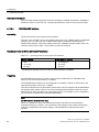
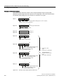
CPU 31xC and CPU 31x: Installation ___________________
Preface
Guide to the S7-300
1
___________________
documentation
SIMATIC
S7-300
CPU 31xC and CPU 31x:
Installation
Operating Instructions
2
___________________
Installation Sequence
3
___________________
S7-300 components
4
___________________
Configuring
5
___________________
Installing
6
___________________
Wiring
7
___________________
Addressing
8
___________________
Commissioning
9
___________________
Maintenance
Debugging functions,
diagnostics and
troubleshooting
10
___________
General technical
11
___________________
specifications
A
___________________
Appendix
This manual is part of the documentation package
with order number:
6ES7398-8FA10-8BA0
03/2011
A5E00105492-12
Legal information
Legal information
Warning notice system
This manual contains notices you have to observe in order to ensure your personal safety, as well as to prevent
damage to property. The notices referring to your personal safety are highlighted in the manual by a safety alert
symbol, notices referring only to property damage have no safety alert symbol. These notices shown below are
graded according to the degree of danger.
DANGER
indicates that death or severe personal injury will result if proper precautions are not taken.
WARNING
indicates that death or severe personal injury may result if proper precautions are not taken.
CAUTION
with a safety alert symbol, indicates that minor personal injury can result if proper precautions are not taken.
CAUTION
without a safety alert symbol, indicates that property damage can result if proper precautions are not taken.
NOTICE
indicates that an unintended result or situation can occur if the corresponding information is not taken into
account.
If more than one degree of danger is present, the warning notice representing the highest degree of danger will
be used. A notice warning of injury to persons with a safety alert symbol may also include a warning relating to
property damage.
Qualified Personnel
The product/system described in this documentation may be operated only by personnel qualified for the specific
task in accordance with the relevant documentation for the specific task, in particular its warning notices and
safety instructions. Qualified personnel are those who, based on their training and experience, are capable of
identifying risks and avoiding potential hazards when working with these products/systems.
Proper use of Siemens products
Note the following:
WARNING
Siemens products may only be used for the applications described in the catalog and in the relevant technical
documentation. If products and components from other manufacturers are used, these must be recommended
or approved by Siemens. Proper transport, storage, installation, assembly, commissioning, operation and
maintenance are required to ensure that the products operate safely and without any problems. The permissible
ambient conditions must be adhered to. The information in the relevant documentation must be observed.
Trademarks
All names identified by ® are registered trademarks of the Siemens AG. The remaining trademarks in this
publication may be trademarks whose use by third parties for their own purposes could violate the rights of the
owner.
Disclaimer of Liability
We have reviewed the contents of this publication to ensure consistency with the hardware and software
described. Since variance cannot be precluded entirely, we cannot guarantee full consistency. However, the
information in this publication is reviewed regularly and any necessary corrections are included in subsequent
editions.
이 기기는 업무용(A급) 전자파 적합기기로서 판매자 또는 사용자는 이 점을 주의하시기 바라며 가정 외의 지역에서 사용하는 것을 목적으로 합니다.
Siemens AG
Industry Sector
Postfach 48 48
90026 NÜRNBERG
GERMANY
A5E00105492-12
Ⓟ 04/2011
Copyright © Siemens AG 2011.
Technical data subject to change
Preface
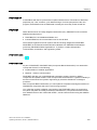
Purpose of this manual
This manual contains essential information about the following:
● Installation
● Communication
● Memory concept
● Cycle and response times
● Technical specifications of the CPUs.
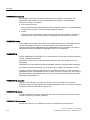
Basic knowledge required
● In order to understand this manual, you require a general knowledge of automation
engineering.
● You require knowledge of STEP 7 basic software.
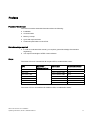
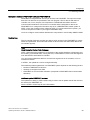
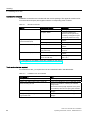
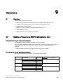
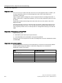
Scope
The name CPU 31xC summarizes all compact CPUs, as table below shows:
CPU
Convention:
CPU designations:
Order number
As of firmware version
CPU 312C
CPU 31xC
6ES7312-5BF04-0AB0
V3.3
CPU 313C
6ES7313-5BG04-0AB0
V3.3
CPU 313C-2 PtP
6ES7313-6BG04-0AB0
V3.3
CPU 313C-2 DP
6ES7313-6CG04-0AB0
V3.3
CPU 314C-2 PtP
6ES7314-6BH04-0AB0
V3.3
CPU 314C-2 DP
6ES7314-6CH04-0AB0
V3.3
CPU 314C-2 PN/DP
6ES7314-6EH04-0AB0
V3.3
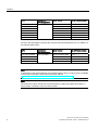
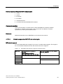
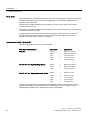
The name CPU 31x summarizes all standard CPUs, as table below shows:
CPU 31xC and CPU 31x: Installation
Operating Instructions, 03/2011, A5E00105492-12
3
Preface
CPU
Convention:
CPU designations:
Order number
As of firmware version
CPU 312
CPU 31x
6ES7312-1AE14-0AB0
V3.3
6ES7314-1AG14-0AB0
V3.3
CPU 315-2 DP
6ES7315-2AH14-0AB0
V3.3
CPU 315-2 PN/DP
6ES7315-2EH14-0AB0
V3.2
CPU 317-2 DP
6ES7317-2AK14-0AB0
V3.3
CPU 317-2 PN/DP
6ES7317-2EK14-0AB0
V3.2
CPU 319-3 PN/DP
6ES7318-3EL01-0AB0
V3.2
CPU 314
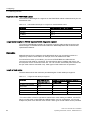
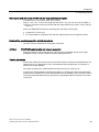
All CPUs with PROFINET properties are grouped under the designation CPU 31x PN/DP, as
the following table shows:
CPU
Convention:
CPU designations:
Order number
As of firmware version
CPU 314C-2 PN/DP
CPU 31x PN/DP
6ES7314-6EH04-0AB0
V3.3
CPU 315-2 PN/DP
6ES7315-2EH14-0AB0
V3.2
CPU 317-2 PN/DP
6ES7317-2EK14-0AB0
V3.2
CPU 319-3 PN/DP
6ES7318-3EL01-0AB0
V3.2
Note
A description of the special features of the failsafe CPUs of the S7 product range is available
in the product information at the following Internet address
(http://support.automation.siemens.com/WW/view/en/11669702/133300).
Note
We reserve the right to include a product Information containing the latest information on
new modules or modules of a more recent version.
CPU 31xC and CPU 31x: Installation
4
Operating Instructions, 03/2011, A5E00105492-12
Preface
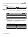
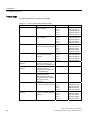
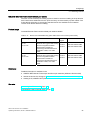
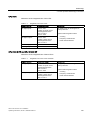
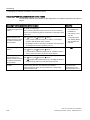
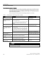
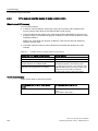
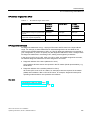
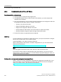
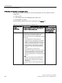
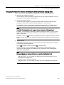
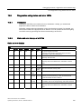
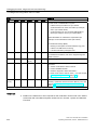
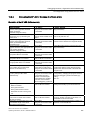
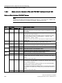
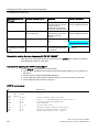
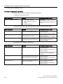
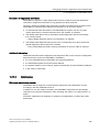
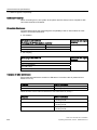
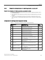
Changes in comparison to the previous version
The following table contains changes from the previous versions of the following
documentation from the S7-300 documentation package:
● Technical specifications manual, version 06/2010
● Operating instructions for installation, version 06/2010
The CPU- 314C-2 PN/DP has been added in delivery stage V3.3. It has the same
functionalities as the CPU 314C-2 DP and also has PROFINET functionalities such as those
of the CPU 315-2 PN/DP.
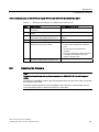
In delivery stage V3.3, the functionality and performance of all C-CPUs and the CPU 317-2
DP were improved compared to their predecessor versions.
Additional information was taken from the chapter "Information on converting to a CPU 31xC
or CPU 31x". If you required more information, however, please refer to the FAQs () on the
Internet.
CPU
312
312C
313C
313C-2
DP
313C-2
PtP
314
314C-2
DP
314C-2
PtP
315-2
DP
317-2
DP
Encryption of blocks
using S7-Block
Privacy
X
X
X
X
X
X
X
X
X
X
Integration of a
maintenance LED
X1, 2
X2
X2
X2
X2
X1, 2
X2
X2
X1, 2
X2
Configurable
increase of control
and monitoring
performance
-
-
-
-
-
-
-
-
X
X
Improved operational limits for PT100
Analog input
-
X
-
-
-
X
X
-
-
Data set routing
-
-
-
X
-
-
1
X
X
X
Expansion of the
block number range
X1
X
X
Number of displayed
diagnostic buffer
entries can be
configured in CPU
RUN mode
X1
X
Reading out the
service data
X1
Extension of SFC 12
with 2 new modes to
trigger the OB 86
during
enabling/disabling
-
Configurable process X
image
Copying of 512 bytes X 1
with SFC 81
X
-
X1
X
X
X
1
X
X
X
1
X
X
X
X1
X
X
X1
X
X
X
X
X1
X
X
X1
X
X
X
X
X
X1
X
X
X1
X
-
-
X
-
-
X
-
X1
X
X
X
X
X
X1
X
X
X1
X
CPU 31xC and CPU 31x: Installation
Operating Instructions, 03/2011, A5E00105492-12
5
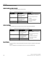
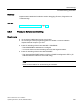
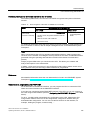
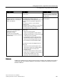
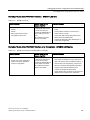
Preface
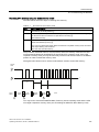
CPU
312
312C
313C
313C-2
DP
313C-2
PtP
314
314C-2
DP
314C-2
PtP
315-2
DP
317-2
DP
X1
X
X
X
X
X1
X
X
X1
X
1
X
X
X
X
X
1
X
X
X
1
X
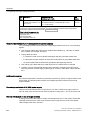
Status information
that can be
monitored by the
status block, in
STEP 7 V5.5 or
higher
X1
X
X
X
X
X1
X
X
X1
X
Number of blocks
that can be
monitored by the
status block
(from 1 to 2)
X1
X
X
X
X
X1
X
X
X1
X
Number of
X1
breakpoints from 2 to
4
X
X
X
X
X1
X
X
X1
X
Local data stack
X1
X
X
X
X
X1
X
X
X1
X
Number of blockrelated messages
(Alarm_S) is
uniformly limited to
300
X1
X
X
X
X
X1
X
X
X1
X
Number of the bit
memories, timers
and counters
X1
X
-
-
-
-
-
-
-
-
DB sizes: Max.
64 KB
X1, 3
X
X
X
X
X1
X
X
X1
X1
Watchdog interrupts:
X1
X
X
X
X
X1
X
X
X1
X1
X1
X
X
X
X
X1
X
X
X1
X1
Increase
Main memory
Performance through X
shorter command
processing times
Standardization
OB 32 to OB 35
Global data
communication of 8
GD circles
System function blocks for integrated technology functions:
SFB 41 to 43
-
-
X1
X1
X1
-
X1
X1
-
-
SFB 44 and 46
-
-
-
-
-
-
X1
X1
-
-
SFB 47 to 49
-
X
X
1
-
X
X
1
-
-
SFB 60 to 62
-
-
-
-
X
1
-
-
X
1
-
-
SFB 63 to 65
-
-
-
-
-
-
-
X1
-
-
1
X
1
X
1
1
This function was already made available to the CPU in an earlier version
2
Available, but without function
3
Max. DB size 32 KB
1
CPU 31xC and CPU 31x: Installation
6
Operating Instructions, 03/2011, A5E00105492-12
Preface
Standards and certifications
For information about standards and approvals, see the section "General technical
specifications (Page 251)".
Recycling and disposal
Because they have ecologically compatible components, the devices described in this
manual can be recycled. For environment-friendly recycling and disposal of your old
equipment, contact a certified disposal facility for electronic scrap.
Service & Support on the Internet
In addition to our documentation, we offer a comprehensive knowledge base online on the
Internet (http://www.siemens.com/automation/service&support).
There you will find:
● Our newsletter containing up-to-date information on your products
● The latest documents in the Siemens Service & Support
(http://www.siemens.com/automation/service&support) search engine.
● A forum for global information exchange by users and specialists.
● Your local representative for automation and drives in our contact database
● Information about on-site services, repairs, spare parts, and lots more.
● Applications and tools for the optimized use of the SIMATIC S7. For example, Siemens
also publishes DP and PN performance measurements on the Internet
(http://www.siemens.com/automation/pd).
CPU 31xC and CPU 31x: Installation
Operating Instructions, 03/2011, A5E00105492-12
7
Preface
CPU 31xC and CPU 31x: Installation
8
Operating Instructions, 03/2011, A5E00105492-12
Table of contents
Preface ...................................................................................................................................................... 3
1
Guide to the S7-300 documentation ........................................................................................................ 15
1.1
Documentation classification .......................................................................................................15
1.2
Guide to the S7-300 documentation ............................................................................................20
2
Installation Sequence .............................................................................................................................. 23
3
S7-300 components................................................................................................................................. 25
4
3.1
Example of an S7-300 configuration............................................................................................25
3.2
Overview of the most important S7-300 modules........................................................................26
Configuring .............................................................................................................................................. 29
4.1
Overview ......................................................................................................................................29
4.2
Basic configuration principles ......................................................................................................29
4.3
Component dimensions ...............................................................................................................32
4.4
Specified clearances....................................................................................................................34
4.5
Arrangement of modules on a single rack ...................................................................................35
4.6
Distribution of modules to several racks ......................................................................................36
4.7
Selection and installation of cabinets...........................................................................................39
4.8
Example: Selecting a cabinet.......................................................................................................41
4.9
4.9.1
4.9.2
4.9.3
4.9.4
4.9.5
4.9.6
Electrical assembly, protective measures and grounding ...........................................................43
Grounding concept and overall structure.....................................................................................43
Installing an S7-300 with grounded reference potential ..............................................................44
Installing an S7-300 with ungrounded reference potential (not CPU 31xC)................................45
Isolated or non-isolated modules? ...............................................................................................46
Grounding measures ...................................................................................................................49
Overview: Grounding ...................................................................................................................52
4.10
Selection of the load power supply ..............................................................................................54
4.11
4.11.1
4.11.2
4.11.2.1
4.11.2.2
4.11.2.3
4.11.2.4
4.11.2.5
4.11.2.6
Planning subnets .........................................................................................................................56
Overview ......................................................................................................................................56
Configuring MPI and PROFIBUS subnets ...................................................................................58
Overview ......................................................................................................................................58
Basic information relating to MPI and PROFIBUS subnets.........................................................58
Multi-Point Interface (MPI) ...........................................................................................................61
PROFIBUS DP interface..............................................................................................................62
Network components of MPI/DP and cable lengths ....................................................................63
Cable lengths of MPI and PROFIBUS subnets ...........................................................................68
CPU 31xC and CPU 31x: Installation
Operating Instructions, 03/2011, A5E00105492-12
9
Table of contents
4.11.3
4.11.3.1
4.11.3.2
4.11.3.3
4.11.3.4
4.11.3.5
4.11.3.6
4.11.3.7
4.11.3.8
4.11.4
4.11.5
4.11.6
5
6
7
Configuring PROFINET subnets................................................................................................. 73
Overview ..................................................................................................................................... 73
PROFINET devices..................................................................................................................... 73
Integration of fieldbuses into PROFINET.................................................................................... 77
PROFINET IO and PROFINET CBA .......................................................................................... 78
PROFINET cable lengths and network expansion ..................................................................... 85
Connectors and other components for Ethernet......................................................................... 88
Example of a PROFINET subnet ................................................................................................ 88
PROFINET IO System ................................................................................................................ 90
Routed network transitions.......................................................................................................... 92
Point-to-point (PtP)...................................................................................................................... 94
Actuator/sensor interface (ASI) ................................................................................................... 94
Installing .................................................................................................................................................. 95
5.1
Installing an S7-300 .................................................................................................................... 95
5.2
Installing the mounting rail .......................................................................................................... 97
5.3
Installing modules on the mounting rail..................................................................................... 100
5.4
Labeling modules ...................................................................................................................... 102
Wiring .................................................................................................................................................... 105
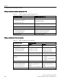
6.1
Requirements for wiring the S7-300 ......................................................................................... 105
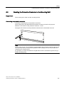
6.2
Bonding the Protective Conductor to the Mounting Rail ........................................................... 107
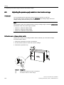
6.3
Adjusting the power supply module to local mains voltage ...................................................... 108
6.4
Wiring the power supply module and the CPU ......................................................................... 109
6.5
Wiring front connectors ............................................................................................................. 111
6.6
Plugging the front connectors into modules.............................................................................. 114
6.7
Wiring I/O modules and compact CPUs with Fast Connect ..................................................... 115
6.8
Labeling the module I/Os .......................................................................................................... 120
6.9
Terminating shielded cables on the shield connection element ............................................... 121
6.10
6.10.1
6.10.2
6.10.3
Wiring bus connectors............................................................................................................... 124
MPI/PROFIBUS bus connector................................................................................................. 124
Setting up the terminating resistor on the PROFIBUS connector............................................. 125
PROFINET bus connector ........................................................................................................ 126
Addressing............................................................................................................................................. 127
7.1
Slot-specific addressing of modules ......................................................................................... 127
7.2
7.2.1
7.2.2
7.2.3
7.2.4
User-specific addressing of modules ........................................................................................ 129
User-specific addressing of modules ........................................................................................ 129
Addressing digital modules ....................................................................................................... 130
Addressing analog modules...................................................................................................... 131
Addressing the integrated I/Os of CPU 31xC ........................................................................... 132
7.3
Addressing on PROFIBUS DP.................................................................................................. 135
7.4
Addressing PROFINET IO ........................................................................................................ 136
7.5
Assigning IP address parameters and the device name .......................................................... 137
CPU 31xC and CPU 31x: Installation
10
Operating Instructions, 03/2011, A5E00105492-12
Table of contents
8
9
10
Commissioning ...................................................................................................................................... 141
8.1
Overview ....................................................................................................................................141
8.2
8.2.1
8.2.2
Commissioning procedure .........................................................................................................141
Procedure: Commissioning the hardware..................................................................................141
Procedure: Software commissioning .........................................................................................143
8.3
Commissioning check list...........................................................................................................145
8.4
8.4.1
8.4.2
8.4.3
8.4.4
8.4.5
8.4.5.1
8.4.5.2
8.4.5.3
8.4.5.4
8.4.5.5
8.4.6
8.4.7
Commissioning the Modules......................................................................................................147
Inserting/replacing a Micro Memory Card..................................................................................147
Initial power on ...........................................................................................................................149
CPU memory reset by means of mode selector switch.............................................................150
Formatting the Micro Memory Card ...........................................................................................154
Connecting the programming device (PG) ................................................................................155
Connect PG/PC to the integrated PROFINET interface of the CPU 31x PN/DP ......................155
Connecting the PG to a node.....................................................................................................156
Connecting the PG to several nodes .........................................................................................157
Using the PG for commissioning or maintenance......................................................................158
Connecting a PG to ungrounded MPI nodes (not CPU 31xC) ..................................................160
Starting SIMATIC Manager........................................................................................................161
Monitoring and modifying inputs and outputs ............................................................................161
8.5
8.5.1
8.5.2
8.5.3
8.5.4
Commissioning PROFIBUS DP .................................................................................................166
Commissioning the PROFIBUS DP network .............................................................................166
Commissioning the CPU as DP master.....................................................................................168
Commissioning the CPU as DP Slave.......................................................................................172
Direct data exchange .................................................................................................................178
8.6
8.6.1
8.6.2
8.6.3
Commissioning PROFINET IO ..................................................................................................180
Requirements.............................................................................................................................180
Commissioning the PROFINET IO system................................................................................181
Configuring the PROFINET IO system ......................................................................................182
Maintenance .......................................................................................................................................... 189
9.1
Overview ....................................................................................................................................189
9.2
Backing up firmware on a SIMATIC Micro Memory Card..........................................................189
9.3
9.3.1
9.3.2
Updating the firmware................................................................................................................191
Firmware update using a Micro Memory Card...........................................................................192
Updating the firmware online (via networks)..............................................................................193
9.4
Backup of project data to a Micro Memory Card .......................................................................195
9.5
Resetting to the Delivery State ..................................................................................................197
9.6
Module installation/removal .......................................................................................................198
9.7
Digital output module: Changing fuses ......................................................................................202
Debugging functions, diagnostics and troubleshooting .......................................................................... 205
10.1
Overview ....................................................................................................................................205
10.2
Reading out service data ...........................................................................................................205
10.3
Identification and maintenance data of the CPU .......................................................................206
10.4
Overview: Debugging functions .................................................................................................208
CPU 31xC and CPU 31x: Installation
Operating Instructions, 03/2011, A5E00105492-12
11
Table of contents
10.5
Overview: Diagnostics............................................................................................................... 212
10.6
Diagnostics functions available in STEP 7................................................................................ 216
10.7
Network infrastructure diagnostics (SNMP) .............................................................................. 217
10.8
10.8.1
10.8.2
10.8.3
10.8.4
10.8.5
10.8.6
10.8.7
Diagnostics using status and error LEDs.................................................................................. 219
Introduction ............................................................................................................................... 219
Status and error displays of all CPUs ....................................................................................... 219
Evaluating the SF LED in the case of software errors .............................................................. 221
Evaluating the SF LED in the case of hardware errors............................................................. 222
Status and error indicators: CPUs with DP interface ................................................................ 224
Status and error indicators: CPUs with PROFINET interface for the S7-300........................... 226
Status and error indicators: PROFINET IO Devices................................................................. 229
10.9
10.9.1
10.9.2
10.9.3
10.9.4
Diagnostics of DP CPUs ........................................................................................................... 230
Diagnostics of DP CPUs operating as DP Master .................................................................... 230
Reading out slave diagnostic data ............................................................................................ 233
Interrupts on the DP Master ...................................................................................................... 238
Structure of the slave diagnostics when the CPU is operated as I-slave ................................. 239
10.10
Diagnostics of PROFINET CPUs .............................................................................................. 247
10.10.1 Diagnostics options of PROFINET IO....................................................................................... 247
10.10.2 Maintenance.............................................................................................................................. 249
11
A
General technical specifications ............................................................................................................ 251
11.1
Standards and certifications...................................................................................................... 251
11.2
Electromagnetic compatibility ................................................................................................... 255
11.3
Transportation and storage conditions for modules.................................................................. 257
11.4
Mechanical and climatic environmental conditions for S7-300 operation................................. 258
11.5
Specification of dielectric tests, protection class, degree of protection, and rated voltage
of S7-300................................................................................................................................... 260
11.6
Rated voltages of S7-300.......................................................................................................... 260
Appendix................................................................................................................................................ 261
A.1
General rules and regulations for S7-300 operation................................................................. 261
A.2
A.2.1
A.2.2
A.2.2.1
A.2.2.2
A.2.2.3
A.2.2.4
A.2.2.5
A.2.3
A.2.4
A.2.5
A.2.6
A.2.7
A.2.8
A.2.9
Protection against electromagnetic interference....................................................................... 263
Basic Points for EMC-compliant system installations ............................................................... 263
Five basic rules for securing EMC ............................................................................................ 265
1. Basic rule for ensuring EMC ................................................................................................. 265
2. Basic rule for ensuring EMC ................................................................................................. 265
3. Basic rule for ensuring EMC ................................................................................................. 266
4. Basic rule for ensuring EMC ................................................................................................. 266
5. Basic rule for ensuring EMC ................................................................................................. 267
EMC-compliant installation of automation systems .................................................................. 267
Examples of an EMC-compliant installation: Cabinet configuration ......................................... 269
Examples of an EMC-compliant installation: Wall mounting..................................................... 270
Cable shielding.......................................................................................................................... 272
Equipotential bonding................................................................................................................ 273
Cable routing inside buildings ................................................................................................... 275
Outdoor routing of cables.......................................................................................................... 277
CPU 31xC and CPU 31x: Installation
12
Operating Instructions, 03/2011, A5E00105492-12
Table of contents
A.3
A.3.1
A.3.2
A.3.3
A.3.4
A.3.5
A.3.6
A.3.7
Lightning and surge voltage protection......................................................................................278
Overview ....................................................................................................................................278
Lightning protection zone concept .............................................................................................279
Rules for the interface between the lightning protection zones 0 and 1 ....................................281
Rules for the interface between the lightning protection zones 1 and 2 ....................................284
Rules for the interface between the lightning protection zones 2 and 3 ....................................286
Example: Surge protection circuit for networked S7-300 CPUs ................................................288
How to protect digital output modules against overvoltages caused by inductance .................290
A.4
Functional safety of electronic control equipment......................................................................292
Glossary ................................................................................................................................................ 295
Index...................................................................................................................................................... 323
CPU 31xC and CPU 31x: Installation
Operating Instructions, 03/2011, A5E00105492-12
13
Table of contents
CPU 31xC and CPU 31x: Installation
14
Operating Instructions, 03/2011, A5E00105492-12
1
Guide to the S7-300 documentation
1.1
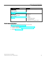
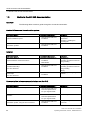
Documentation classification
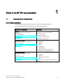
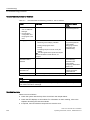
Documentation classification
The documentation listed below is part of the S7-300 documentation package.
You can also find this on the Internet and the corresponding entry ID.
Name of the documentation
Description
Manual
Description of:
CPU 31xC and CPU 31x: Technical
specifications
Entry ID: 12996906
(http://support.automation.siemens.com/WW/view
/en/12996906)
Operating Instructions
Operator controls and indicators
Communication
Memory concept
Cycle and response times
Technical specifications
Description of:
CPU 31xC and CPU 31x: Installation
Entry ID: 13008499
(http://support.automation.siemens.com/WW/view
/en/13008499)
Configuring
Installing
Wiring
Addressing
Commissioning
Maintenance and the test functions
Diagnostics and troubleshooting
Operating Instructions
Description of the specific technological functions:
CPU 31xC: Technological functions
incl. CD
Positioning
Counting
Entry ID: 12429336
Point-to-point connection
(http://support.automation.siemens.com/WW/view
Rules
/en/12429336)
The CD contains examples of the technological
functions.
CPU 31xC and CPU 31x: Installation
Operating Instructions, 03/2011, A5E00105492-12
15
Guide to the S7-300 documentation
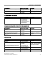
1.1 Documentation classification
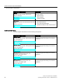
Name of the documentation
Description
Manual
Descriptions and technical specifications of the
following modules:
S7-300 Automation System: Module data
Entry ID: 8859629
(http://support.automation.siemens.com/WW/view
/en/8859629)
Signal modules
List Manual
Instruction List of the S7-300 CPUs and ET- 200
CPUs
List of the instruction set of the CPUs and
their execution times.
List of the executable blocks
(OBs/SFCs/SFBs) and their execution times.
Entry ID: 31977679
(http://support.automation.siemens.com/WW/view
/en/31977679)
Power supplies
Interface modules
Additional information
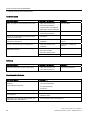
You also require information from the following descriptions:
Name of the documentation
Description
Description of examples showing the various
S7-300 Automation System: Getting Started CPU commissioning phases leading to a functional
application.
31x: Commissioning
Getting Started
Entry ID: 15390497
(http://support.automation.siemens.com/WW/view
/en/15390497)
Description of examples showing the various
S7-300 Automation System: Getting Started CPU commissioning phases leading to a functional
application.
31xC: Commissioning
Getting Started
Entry ID: 48077635
(http://support.automation.siemens.com/WW/view
/en/48077635)
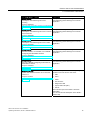
Getting Started
First steps in commissioning CPU 31xC:
Positioning with analog output
Description of examples showing the various
commissioning phases leading to a functional
application.
Entry ID: 48070939
(http://support.automation.siemens.com/WW/view
/en/48070939)
Getting Started
First steps in commissioning CPU 31xC:
Positioning with digital output
Description of examples showing the various
commissioning phases leading to a functional
application.
Entry ID: 48077520
(http://support.automation.siemens.com/WW/view
/en/48077520)
CPU 31xC and CPU 31x: Installation
16
Operating Instructions, 03/2011, A5E00105492-12
Guide to the S7-300 documentation
1.1 Documentation classification
Name of the documentation
Description
Getting Started
Description of examples showing the various
commissioning phases leading to a functional
application.
First steps in commissioning CPU 31xC:
Counting
Entry ID: 48064324
(http://support.automation.siemens.com/WW/view
/en/48064324)
Description of examples showing the various
First steps in commissioning CPU 31xC: Point-to- commissioning phases leading to a functional
application.
point connection
Getting Started
Entry ID: 48064280
(http://support.automation.siemens.com/WW/view
/en/48064280)
Getting Started
First steps in commissioning CPU 31xC: Rules
Entry ID: 48077500
(http://support.automation.siemens.com/WW/view
/en/48077500)
Getting Started
CPU315-2 PN/DP, 317-2 PN/DP, 319-3 PN/DP:
Configuring the PROFINET interface
Description of examples showing the various
commissioning phases leading to a functional
application.
Description of examples showing the various
commissioning phases leading to a functional
application.
Entry ID: 48080216
(http://support.automation.siemens.com/WW/view
/en/48080216)
Getting Started
CPU 317-2 PN/DP: Configuring an ET 200S as
PROFINET IO device
Description of examples showing the various
commissioning phases leading to a functional
application.
Entry ID: 19290251
(http://support.automation.siemens.com/WW/view
/en/19290251)
Reference Manual
System and standard functions for S7-300/400,
volume 1/2
Overview of objects included in the operating
systems for S7-300 and S7-400 CPUs:
Entry ID: 1214574
(http://support.automation.siemens.com/WW/view
/en/1214574)
OBs
SFCs
SFBs
IEC functions
Diagnostics data
System status list (SSL)
Events
This manual is part of the STEP 7 reference
information.
You can also find the description in the STEP 7
Online Help.
CPU 31xC and CPU 31x: Installation
Operating Instructions, 03/2011, A5E00105492-12
17
Guide to the S7-300 documentation
1.1 Documentation classification
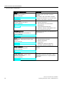
Name of the documentation
Description
Manual
This manual provides a complete overview of
programming with the STEP 7 Standard
Package.
Programming with STEP 7
Entry ID: 18652056
(http://support.automation.siemens.com/WW/view This manual is part of the STEP 7 Standard
Package basic information. You can also find a
/en/18652056)
description in the STEP 7 Online Help.
System Manual
Basic description of PROFINET:
PROFINET System Description
Entry ID: 19292127
(http://support.automation.siemens.com/WW/view
/en/19292127)
Programming manual
From PROFIBUS DP to PROFINET IO
Network components
Data exchange and communication
PROFINET IO
Component Based Automation
Application example of PROFINET IO and
Component Based Automation
Guideline for the migration from PROFIBUS DP
to PROFINET I/O.
Entry ID: 19289930
(http://support.automation.siemens.com/WW/view
/en/19289930)
Manual
Description of:
SIMATIC NET: Twisted Pair and Fiber-Optic
Networks
Industrial Ethernet networks
Network configuration
Entry ID: 8763736
(http://support.automation.siemens.com/WW/view
/en/8763736)
Configuring Manual
Configure SIMATIC iMap plants
Components
Guidelines for setting up networked
automation systems in buildings, etc.
Description of the SIMATIC iMap configuration
software
Entry ID: 22762190
(http://support.automation.siemens.com/WW/view
/en/22762190)
Configuring Manual
SIMATIC iMap STEP 7 AddOn, create
PROFINET components
Entry ID: 22762278
(http://support.automation.siemens.com/WW/view
/en/22762278)
Descriptions and instructions for creating
PROFINET components with STEP 7 and for
using SIMATIC devices in Component Based
Automation
CPU 31xC and CPU 31x: Installation
18
Operating Instructions, 03/2011, A5E00105492-12
Guide to the S7-300 documentation
1.1 Documentation classification
Name of the documentation
Description
Function Manual
Description of the system property "Isochronous
mode"
Isochronous mode
Entry ID: 15218045
(http://support.automation.siemens.com/WW/view
/en/15218045)
System Manual
Description of:
Communication with SIMATIC
Entry ID: 1254686
(http://support.automation.siemens.com/WW/view
/en/1254686)
Basics
Services
Networks
Communication functions
Connecting PGs/OPs
Engineering and configuring in STEP 7
Service & support on the Internet
Information on the following topics can be found on the Internet
(http://www.siemens.com/automation/service):
● Contacts for SIMATIC (http://www.siemens.com/automation/partner)
● Contacts for SIMATIC NET (http://www.siemens.com/simatic-net)
● Training (http://www.sitrain.com)
CPU 31xC and CPU 31x: Installation
Operating Instructions, 03/2011, A5E00105492-12
19
Guide to the S7-300 documentation
1.2 Guide to the S7-300 documentation
1.2
Guide to the S7-300 documentation
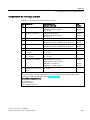
Overview
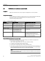
The following tables contain a guide through the S7-300 documentation.
Ambient influence on the automation system
Information about ...
is available in the manual ...
What provisions do I have to make for automation
system installation space?
How do environmental conditions influence the
automation system?
In Section ...
CPU 31xC and CPU 31x:
Installation
Configuring – Component
dimensions
CPU 31xC and CPU 31x:
Installation
Appendix
Mounting – Installing the
mounting rail
Isolation
Information about ...
is available in the manual ...
Which modules can I use if electrical isolation is
required between sensors/actuators?
CPU 31xC and CPU 31x:
Installation
Module data
CPU 31xC and CPU 31x:
Installation
Under what conditions do I have to isolate the
modules electrically?
How do I wire that?
Under which conditions do I have to isolate stations
electrically?
In Section ...
Configuring – Electrical
assembly, protective measures
and grounding
Configuring – Electrical
assembly, protective measures
and grounding
Wiring
How do I wire that?
CPU 31xC and CPU 31x:
Installation
Configuring – Configuring
subnets
Communication between sensors/actuators and the PLC
Information about ...
is available in the manual ...
Which module is suitable for my sensor/actuator?
CPU 31xC and CPU 31x:
Technical specifications
For your signal module
CPU 31xC and CPU 31x:
Technical specifications
For your signal module
CPU 31xC and CPU 31x:
Installation
How many sensors/actuators can I connect to the
module?
How do I connect my sensors/actuators to the
automation system, using the front connector?
In Section ...
Technical specifications
Technical specifications
Wiring – Wiring the front
connector
CPU 31xC and CPU 31x: Installation
20
Operating Instructions, 03/2011, A5E00105492-12
Guide to the S7-300 documentation
1.2 Guide to the S7-300 documentation
Information about ...
is available in the manual ...
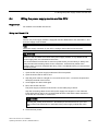
When do I need expansion modules (EM) and how
do I connect them?
In Section ...
CPU 31xC and CPU 31x:
Installation
Configuring – Distribution of
modules across multiple racks
How do I mount modules on racks / mounting rails?
CPU 31xC and CPU 31x:
Installation
Assembly – Installing modules on
the mounting rail
The use of local and distributed IOs
Information about ...
is available in the manual ...
Which range of modules do I want to use?
Module data
(for centralized IOs/
expansion devices)
of the respective peripheral
(for distributed IOs/
PROFIBUS DP)
In Section ...
–
Configuration consisting of the central controller and expansion units
Information about ...
is available in the manual ...
Which rack / mounting rail is most suitable for my
application?
In Section ...
CPU 31xC and CPU 31x:
Installation
Configuring
Which interface modules (IM) do I need to connect
the expansion units to the central controller?
CPU 31xC and CPU 31x:
Installation
Configuring – Distribution of
modules across multiple racks
What is the right power supply (PS) for my
application?
CPU 31xC and CPU 31x:
Installation
Configuring
CPU performance
Information about ...
is available in the manual ...
In Section ...
Which memory concept is best suited to my
application?
CPU 31xC and CPU 31x:
Technical specifications
Memory concept
How do I insert and remove Micro Memory Cards?
CPU 31xC and CPU 31x:
Installation
Commissioning – Commissioning
modules – Removing / inserting a
Micro Memory Card (MMC)
Which CPU meets my demands on performance?
S7-300 instruction list:
CPU 31xC and CPU 31x
–
Length of the CPU response / execution times
CPU 31xC and CPU 31x:
Technical specifications
–
Which technological functions are implemented?
Technological functions
–
How can I use these technological functions?
Technological functions
–
CPU 31xC and CPU 31x: Installation
Operating Instructions, 03/2011, A5E00105492-12
21
Guide to the S7-300 documentation
1.2 Guide to the S7-300 documentation
Communication
Information about ...
is available in the manual ...
In Section ...
Which principles do I have to take into account?
CPU 31xC and CPU 31x:
Technical specifications
Communication with SIMATIC
PROFINET System Description
Options and resources of the CPU
CPU 31xC and CPU 31x:
Technical specifications
Technical specifications
How to use communication processors (CPs) to
optimize communication
CP Manual
–
Which type of communication network is best
suited to my application?
CPU 31xC and CPU 31x:
Installation
Configuring – Configuring
subnets
How do I network the various components?
CPU 31xC and CPU 31x:
Installation
Configuring – Configuring
subnets
What to take into account when configuring
PROFINET networks
SIMATC NET, twisted-pair and
fiber-optic networks
(6GK1970-1BA10-0AA0)
Network configuration
PROFINET System Description
Installation and commissioning
Communication
Software
Information about ...
is available in the manual ...
Software requirements of my S7-300 system
CPU 31xC and CPU 31x:
Technical specifications
In Section ...
Technical specifications
Supplementary features
Information about ...
is available in ...
How can I implement operation and monitoring
functions?
The relevant manual:
For text-based displays
For Operator Panels
For WinCC
How to integrate process control modules
Respective PCS7 manual
What options are offered by redundant and failsafe systems?
S7-400H – Fault-Tolerant Systems
Failsafe systems
Information to be observed when migrating from
PROFIBUS DP to PROFINET IO
From PROFIBUS DP to PROFINET IO
(Human Machine Interface)
CPU 31xC and CPU 31x: Installation
22
Operating Instructions, 03/2011, A5E00105492-12
2
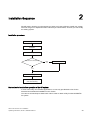
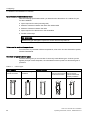
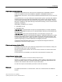
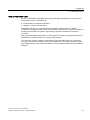
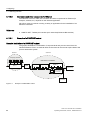
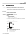
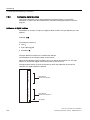
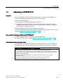
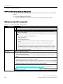
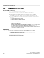
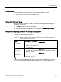
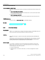
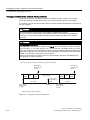
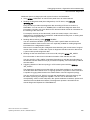
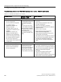
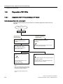
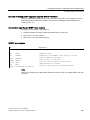
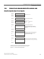
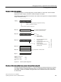
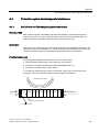
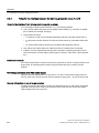
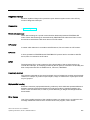
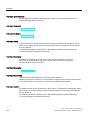
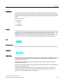
Installation Sequence
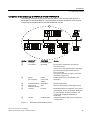
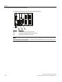
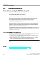
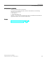
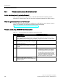
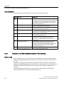
We will start by showing you the sequence of steps you have to follow to install your system.
Then we will go on to explain the basic rules that you should follow, and how you can modify
an existing system.
Installation procedure
&RQILJXUDWLRQ
,QVWDOODWLRQ
:LULQJ
,VDVXEQHWWREHEXLOWXS"
<(6
1HWZRUNLQJ
12
$GGUHVVLQJ
,QVWDOODWLRQFRPSOHWHGFRQWLQXH
ZLWKFRPPLVVLRQLQJ
Basic rules for trouble-free operation of the S7 system
In view of the many and versatile applications, we can only provide basic rules for the
electrical and mechanical installation in this section.
You have to at least keep to these basic rules in order to obtain a fully functional SIMATICS7 system.
CPU 31xC and CPU 31x: Installation
Operating Instructions, 03/2011, A5E00105492-12
23
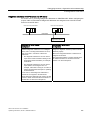
Installation Sequence
Modifying the existing S7 system structure
To modify the configuration of an existing system, proceed as described earlier.
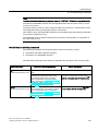
Note
When adding a new signal module, always refer to the relevant module information.
Reference
Also refer to the description of the various modules in the manual: SIMATIC S7-300
Automation Systems, Module Data Manual.
CPU 31xC and CPU 31x: Installation
24
Operating Instructions, 03/2011, A5E00105492-12
3
S7-300 components
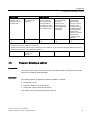
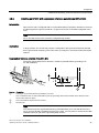
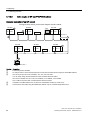
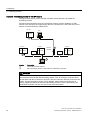
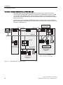
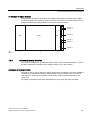
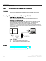
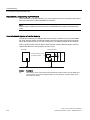
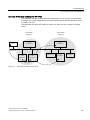
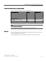
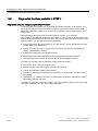
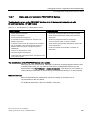
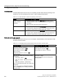
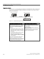
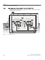
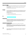
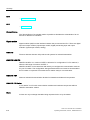
3.1
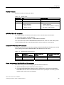
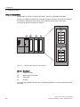
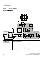
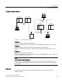
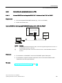
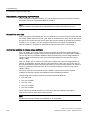
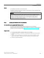
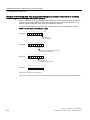
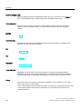
Example of an S7-300 configuration
6)
%86)
'&9
)5&(
581
6723
6)
%86)
'&9
)5&(
581
6723
Number
①
②
③
④
⑤
Description
Power supply (PS) module
Central processing unit (CPU); the example in the diagram shows a CPU 31xC with
integrated I/O.
Signal module (SM)
PROFIBUS bus cable
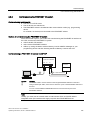
Cable for connecting a programming device (PG)
You use a programming device (PG) to program the S7300 PLC. Use the PG cable to
interconnect the PG with the CPU.
To commission or program a CPU with PROFINET connection, you also have the choice to
connect the programming device to the PROFINET port of the CPU via Ethernet cable.
Several S7-300 CPUs communicate with one another and with other SIMATIC S7 PLCs via
the PROFIBUS cable. Several S7-300 are connected via the PROFIBUS bus cable.
CPU 31xC and CPU 31x: Installation
Operating Instructions, 03/2011, A5E00105492-12
25
S7-300 components
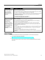
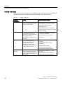
3.2 Overview of the most important S7-300 modules
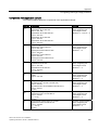
3.2
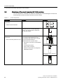
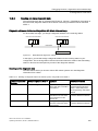
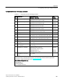
Overview of the most important S7-300 modules
You can choose from a number of modules for installing and commissioning the S7-300. The
most important modules and their functions are shown below.
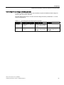
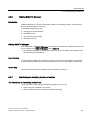
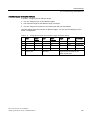
Table 3- 1
S7-300 components:
Component
Function
Mounting rail
S7-300 racks
Illustration
Accessories:
Shield connection element
Power supply (PS) module
The PS converts the line voltage
(120/230 VAC) into a 24 VDC operating
voltage, and supplies the S7-300 and its
24 VDC load circuits.
CPU
The CPU executes the user program, supplies
5 V to the S7-300 backplane bus, and
communicates with other nodes of an MPI
network via the MPI interface.
Accessories:
Front connectors (CPU 31xC only)
6,(0(16
Additional features of specific CPUs:
DP master or DP slave on a PROFIBUS
subnet
Technological functions
Point-to-point connection
Ethernet communication via integrated
PROFINET interface
A CPU 31xC, for example
A CPU 312, 314, or 315-2 DP,
for example
A CPU 317, for example
CPU 31xC and CPU 31x: Installation
26
Operating Instructions, 03/2011, A5E00105492-12
S7-300 components
3.2 Overview of the most important S7-300 modules
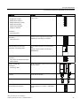
Component
Function
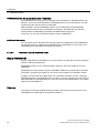
Signal modules (SM)
The SM matches different process signal levels
to the S7-300.
Digital input modules
Digital output modules
Digital input/output module
Analog input modules
Analog output modules
Analog I/O modules
Illustration
Accessories:
Front connectors
Function modules (FM)
Accessories:
Front connectors
Communication processor (CP)
The FM performs time-critical and memoryintensive process signal processing tasks.
Positioning or controlling, for example
Accessories: Connecting cable
The CP relieves the CPU of communication
tasks.
SIMATIC TOP connect
Wiring of digital modules
Example: CP 342-5 DP for connecting to
PROFIBUS DP
Accessories:
Front connector module with ribbon
cable terminals
Interface module (IM)
Accessories:
The IM connects the various rows in an S7-300
with one another.
Connecting cable
PROFIBUS bus cable with bus
connector
Connects the nodes of an MPI or PROFIBUS
subnet with one another.
PG cable
Connects a PG/PC to a CPU
RS 485 repeater
The repeater is used to amplify the signals and
to couple segments of an MPI or PROFIBUS
subnet.
RS 485 Diagnostic Repeater
CPU 31xC and CPU 31x: Installation
Operating Instructions, 03/2011, A5E00105492-12
27
S7-300 components
3.2 Overview of the most important S7-300 modules
Component
Function
Switch
A switch is used to interconnect the Ethernet
nodes.
Illustration
Twisted-pair cables with RJ45
connectors.
Interconnects devices with Ethernet interface
(a switch with a CPU 317-2 PN/DP, for
example)
Programming device (PG) or PC with
the STEP 7 software package
You need a PG to configure, set parameters
for, program and test your S7-300.
CPU 31xC and CPU 31x: Installation
28
Operating Instructions, 03/2011, A5E00105492-12
4
Configuring
4.1
Overview
There, you can find all the necessary information
● for the mechanical configuration of an S7-300,
● for the electrical configuration of an S7-300,
● that has to be observed in networking.
Reference
For more detailed information, refer to
● the Communication with SIMATIC manual or
● the SIMATIC NET twisted pair and fiber optic networks manual (6GK1970-1BA10-0AA0)
4.2
Basic configuration principles
Important information for engineering
WARNING
Open equipment
S7-300 modules are open equipment. That is, the S7-300 must be installed in a cubicle,
cabinet or electrical control room which can only be accessed using a key or tool. Only
trained or authorized personnel are allowed access to such cubicles, cabinets or electrical
operating rooms.
CAUTION
Operation of an S7-300 in plants or systems is defined by special set of rules and
regulations, based on the relevant field of application. Observe the safety and accident
prevention regulations for specific applications, for example, the machine protection
directives. This chapter and the appendix General rules and regulations on S7-300
operation provide an overview of the most important rules you need to observe when
integrating an S7-300 into a plant or a system.
CPU 31xC and CPU 31x: Installation
Operating Instructions, 03/2011, A5E00105492-12
29
Configuring
4.2 Basic configuration principles
Central unit (CU) and expansion module (EM)
An S7-300 PLC consists of a central unit (CU) and of one or multiple expansion modules.
The rack containing the CPU is the central unit (CU). Racks equipped with modules and
connected to the CU form the expansion modules (EMs) of the system.
Use of an expansion module (EM)
You can use EMs if the CU runs out of slots for your application.
When using EMs, you might require additional power supply modules in addition to the extra
racks and interface modules (IM). When using interface modules you must ensure
compatibility of the partner stations.
Racks
The rack for your S7-300 is a mounting rail. You can use this rail to mount all modules of
your S7-300 system.
CPU 31xC and CPU 31x: Installation
30
Operating Instructions, 03/2011, A5E00105492-12
Configuring
4.2 Basic configuration principles
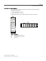
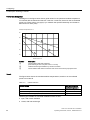
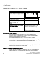
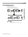
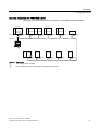
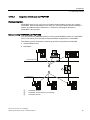
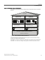
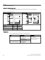
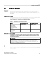
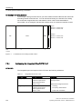
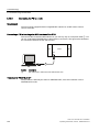
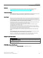
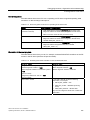
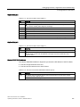
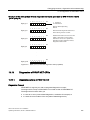
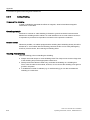
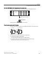
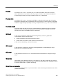
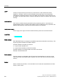
Horizontal and vertical installation
You can mount an S7-300 either vertically or horizontally. The following ambient air
temperatures are permitted:
● Vertical assembly: 0 °C to 40 °C
● Horizontal assembly: 0 °C to 60 °C
Always install the CPU and power supply modules on the left or at the bottom.
60
60
60
60
DC5
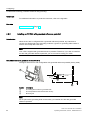
V
FRCE
RUN
ST
OP
60
60
36
&38
60 60 60 60 60 60 60 60
60
DC5
FRCE
RUN
ST
OP
60
&38
36
Number
①
②
③
Description
Vertical structure of the S7-300
Horizontal structure of the S7-300
Mounting rail
CPU 31xC and CPU 31x: Installation
Operating Instructions, 03/2011, A5E00105492-12
31
Configuring
4.3 Component dimensions
4.3
Component dimensions
Length of the mounting rails
Table 4- 1
Mounting rails - Overview
Mounting rail length
Usable length for modules
Order number
160 mm
120 mm
6ES7390-1AB60-0AA0
482.6 mm
450 mm
6ES7390-1AE80-0AA0
530 mm
480 mm
6ES7390-1AF30-0AA0
830 mm
780 mm
6ES7390-1AJ30-0AA0
2000 mm
cut to length as required
6ES7390-1BC00-0AA0
In contrast to other rails, the 2 m mounting rail is not equipped with any fixing holes. These
must be drilled, allowing optimal adaptation of the 2 m rail to your application.
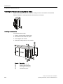
Installation Dimensions of the Modules
Table 4- 2
Module width
Module
Width
Power supply module PS 307, 2 A
40 mm
Power supply module PS 307, 5 A
60 mm
Power supply module PS 307, 10 A
80 mm
CPU
For information on assembly dimensions, refer to
the technical data in CPU 31xC and CPU 31x
manual, technical data.
Analog input/output modules
40 mm
Digital input/output modules
40 mm
Simulator module SM 374
40 mm
Interface modules IM 360 and IM 365
40 mm
Interface module IM 361
80 mm
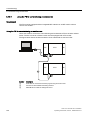
● Module height: 125 mm
● Module height with shield connection element 185 mm
● Maximum assembly depth: 130 mm
● Maximum assembly depth of a CPU with an inserted DP connector with angled cable
feed: 140 mm
● Maximum assembly depth with open front panel (CPU): 180 mm
Dimensions of other modules such as CPs, FMs etc. are found in the relevant manuals.
CPU 31xC and CPU 31x: Installation
32
Operating Instructions, 03/2011, A5E00105492-12
Configuring
4.3 Component dimensions
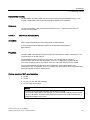
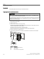
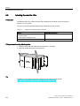
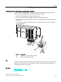
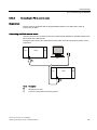
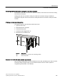
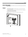
Shield connection element
The shield connection element provides you with a comfortable means of bonding all
shielded cables of your S7 modules to ground, that is, via direct connection of the shield
connection element with the mounting rail.
36
&38
Number
①
②
Description
Shielding terminals
Bracket
Mount the bracket (order number 6ES7390-5AA0-0AA0) to the rail using the two screw bolts.
If you use a shield connection element, the dimension specifications apply from the lower
edge of the shield connection element.
● Width of the shield connection element: 80 mm
● Number of shielding terminals you can install per shield connection element: max. 4
Table 4- 3
Shielding terminals - Overview
Cable with shielding diameter
Shielding terminal order number
Cable with 2 mm to 6 mm shielding diameter
6ES7390-5AB00–0AA0
Cable with 3 mm to 8 mm shielding diameter
6ES7390-5BA00–0AA0
Cable with 4 mm to 13 mm shielding diameter
6ES7390-5CA00–0AA0
CPU 31xC and CPU 31x: Installation
Operating Instructions, 03/2011, A5E00105492-12
33
Configuring
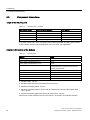
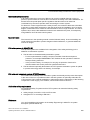
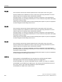
4.4 Specified clearances
4.4
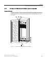
Specified clearances
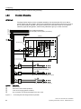
You must maintain the clearance shown in the figure in order to provide sufficient space for
installing the modules, and to allow the dissipation of heat generated by the modules.
The S7-300 assembly on multiple racks shown in the figure below shows the clearance
between racks and adjacent components, cable ducts, cabinet walls etc.
For example, when routing your module wiring through cable duct, the minimum clearance
between the bottom edge of the shield connection element and the cable duct is 40 mm.
PP
&38
60 60
60
PP
PPD
PP
36
&38
PP
D
60
60
PP
PP
Number
①
②
Description
Wiring with cable duct
Minimum clearance between the cable duct and the bottom edge of the shield
connection element is 40 mm.
CPU 31xC and CPU 31x: Installation
34
Operating Instructions, 03/2011, A5E00105492-12
Configuring
4.5 Arrangement of modules on a single rack
4.5
Arrangement of modules on a single rack
Reasons for using one or multiple racks
The number of racks you need will depend on your application.
Reasons for using a single rack
Compact, space-saving use of all your
modules
Local use of all modules
Fewer signals to be processed
Reasons for distributing modules between
several racks
More signals to be processed
Insufficient number of slots
Note
If you opt for the installation on a single rack, insert a dummy module to the right of the CPU
(order no.: 6ES7370-0AA01-0AA0). This gives you the option of adding a second rack for
your application if this is necessary later, simply by replacing the dummy module with an
interface module, without having to reinstall and rewire the first rack.
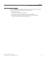
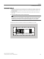
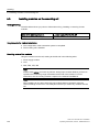
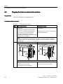
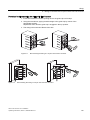
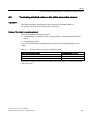
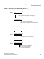
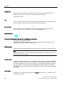
Rules: Layout of modules on a single module rack
The following rules apply to module installations on a single rack:
● No more than eight modules (SM, FM, CP) may be installed to the right of the CPU.
● The accumulated power consumption of modules mounted on a rack may not exceed 1.2
A on the S7-300 backplane bus.
Reference
Additional information is available in the technical data, for example, in the SIMATIC S7-300
Automation Systems Manual, Module data, or in the S7-300 Manual, CPU 31xC and CPU
31x, Technical Data.
Example
The figure below shows a layout with eight signal modules in an S7-300 assembly.
36
&38
60 60 60 60 60 60 60 60
CPU 31xC and CPU 31x: Installation
Operating Instructions, 03/2011, A5E00105492-12
35
Configuring
4.6 Distribution of modules to several racks
4.6
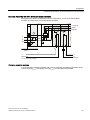
Distribution of modules to several racks
Exceptions
With CPU 312 and CPU 312C, only a single-row configuration on a rack is possible.
Using interface modules
If you are planning an assembly in multiple racks, then you will need interface modules (IM).
An interface module routes the backplane bus of an S7-300 to the next rack.
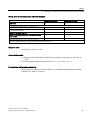
The CPU is always located on rack 0.
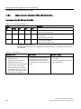
Table 4- 4
Interface modules - Overview
Properties
Two or more rows
Cost-effective 2-row configuration
Send IM in rack 0
IM 360
order no.: 6ES7360-3AA01-0AA0
IM 365
order no.: 6ES7365-0AB01-0AA0
Receiver IM in racks 1 to 3
IM 361
order no.: 6ES7361-3CA01-0AA0
IM 365
(hard-wired to send IM 365)
Maximum number of
expansion modules
3
1
Length of connecting cables 1 m (6ES7368-3BB01-0AA0)
2.5 m (6ES7368-3BC51-0AA0)
5 m (6ES7368-3BF01-0AA0)
10 m (6ES7368-3CB01-0AA0)
1 m (hard-wired)
Comments
Rack 1 can only receive signal modules; the
accumulated current load is limited to 1.2 A,
whereby the maximum for rack 1 is 0.8 A.
-
These restrictions do not apply to operation with
interface modules IM 360/IM 361
Rules: Distribution of modules to several racks
Please note the following points if you wish to arrange your modules on multiple racks:
● The interface module always uses slot 3
(slot 1: power supply module; slot 2: CPU, slot 3: Interface module)
● It is always on the left before the first signal module.
● No more than 8 modules (SM, FM, CP) are permitted per rack.
● The number of modules (SM, FM, CP) is limited by the permitted current consumption on
the S7-300 backplane bus. The cumulative current consumption of 1.2 A in row 0 (CPU)
and 0.8 A each in the expansion rows 1 to 3 must not be exceeded.
Note
The current consumption of specific modules is listed in the SIMATIC S7-300 Automation
Systems Manual, Module data.
CPU 31xC and CPU 31x: Installation
36
Operating Instructions, 03/2011, A5E00105492-12
Configuring
4.6 Distribution of modules to several racks
Rules: Interference-proof interfacing
Special shielding and grounding measures are not required if you interconnect the CU and
EM using suitable interface modules (Send IM and Receive IM).
However, you must ensure
● a low impedance interconnection of all racks,
● that the racks of a grounded assembly are grounded in a star pattern,
● that the contact springs on the racks are clean and not bent, thus ensuring that
interference currents are properly discharged to ground.
CPU 31xC and CPU 31x: Installation
Operating Instructions, 03/2011, A5E00105492-12
37
Configuring
4.6 Distribution of modules to several racks
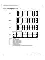
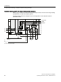
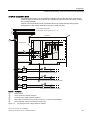
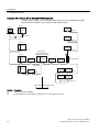
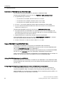
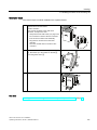
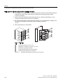
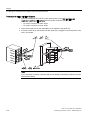
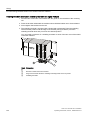
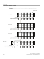
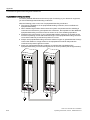
Example: Full assembly using four racks
The figure shows the arrangement of modules in an S7-300 assembly on 4 racks.
36
,0
60 60 60 60 60 60 60 60
36
,0
60 60 60 60 60 60 60 60
36
,0
60 60 60 60 60 60 60 60
Number
①
②
③
④
⑤
⑥
36
&38
,0
60 60 60 60 60 60 60 60
Description
Rack 0 (central unit)
Rack 1 (expansion module)
Rack 2 (expansion module)
Rack 3 (expansion module)
Connection line 368
Limitation for CPU 31xC
When this CPU is used, do not insert signal module 8 into Rack 4.
CPU 31xC and CPU 31x: Installation
38
Operating Instructions, 03/2011, A5E00105492-12
Configuring
4.7 Selection and installation of cabinets
4.7
Selection and installation of cabinets
Reasons for installing an S7-300 in a cabinet
Your S7-300 should be installed in a cabinet,
● if you plan a larger system,
● if you are using your S7-300 systems in an environment subject to interference or
contamination, and
● to meet UL/CSA requirements for cabinet installation.
Selecting and dimensioning cabinets
Take the following criteria into account:
● ambient conditions at the cabinet's place of installation
● the specified mounting clearance for racks (mounting rails)
● accumulated power loss of all components in the cabinet.
The ambient conditions (temperature, humidity, dust, chemical influence, explosion hazard)
at the cabinet's place of installation determine the degree of protection (IP xx) required for
the cabinet.
Reference for degrees of protection
For additional information on the degrees of protection, refer to IEC 60529 and DIN 40050.
The power dissipation capability of cabinets
The power dissipation capability of a cabinet depends on its type, ambient temperature and
on the internal arrangement of devices.
Reference for power loss
For detailed information on dissipatable power loss, refer to the Siemens catalogs. You can
find these at: https://mall.automation.siemens.com/de/guest/guiRegionSelector.asp
(https://mall.automation.siemens.com/de/guest/guiRegionSelector.asp)
CPU 31xC and CPU 31x: Installation
Operating Instructions, 03/2011, A5E00105492-12
39
Configuring
4.7 Selection and installation of cabinets
Specification of cabinet dimensions
Note the following specifications when you determine the dimensions of a cabinet for your
S7-300 installation:
● Space required for racks (mounting rails)
● Minimum clearance between the racks and cabinet walls
● Minimum clearance between the racks
● Space required for cable ducts or fan assemblies
● Position of the stays
WARNING
Modules may get damaged if exposed to excess ambient temperatures.
Reference for ambient temperatures
For information on permitted ambient temperatures, refer to the S7-300 Automation System,
Module Data Manual.
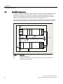
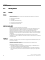
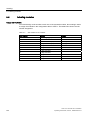
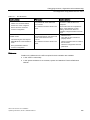
Overview of typical cabinet types
The table below gives you an overview of commonly used cabinet types. It shows you the
applied principle of heat dissipation, the calculated maximum power loss and the degree of
protection.
Table 4- 5
Cabinet types
Open cabinets
Through-ventilation by
natural convection
Closed cabinets
Increased throughventilation
Natural convection
Forced convection with Forced convection with
rack fan, improvement heat exchanger,
of natural convection
internal and external
auxiliary ventilation
CPU 31xC and CPU 31x: Installation
40
Operating Instructions, 03/2011, A5E00105492-12
Configuring
4.8 Example: Selecting a cabinet
Open cabinets
Closed cabinets
Mainly inherent heat
dissipation, with a
small portion across
the cabinet wall.
Higher heat dissipation Heat dissipation only
with increased air
across the cabinet
movement.
wall; only low power
losses permitted. In
most cases, the heat
accumulates at the top
of the cabinet interior.
Heat dissipation only
across the cabinet
wall. Forced
convection of the
interior air improves
heat dissipation and
prevents heat
accumulation.
Heat dissipation by
heat exchange
between heated
internal air and cool
external air. The
increased surface of
the pleated profile of
the heat exchanger
wall and forced
convection of internal
and external air
provide good heat
dissipation.
Degree of protection
IP 20
Degree of protection
IP 20
Degree of protection
IP 54
Degree of protection
IP 54
Degree of protection
IP 54
Typical power dissipation under following marginal conditions:
Cabinet size: 600 mm x 600 mm x 2,200 mm
Difference between the outer and inner temperature of the cabinet is 20 °C (for other temperature differences refer to
the temperature charts of the cabinet manufacturer)
up to 700 W
4.8
up to 2,700 W (with
fine filter up to
1,400 W)
up to 260 W
up to 360 W
up to 1,700 W
Example: Selecting a cabinet
Introduction
The sample below clearly shows the maximum permitted ambient temperature at a specific
power loss for different cabinet designs.
Installation
The following device configuration should be installed in a cabinet:
● Central unit, 150 W
● Expansion modules, each with 150 W
● Load power supply under full load, 200 W
This results in an accumulated power loss of 650 W.
CPU 31xC and CPU 31x: Installation
Operating Instructions, 03/2011, A5E00105492-12
41
Configuring
4.8 Example: Selecting a cabinet
Power loss dissipated
The diagram in the figure below shows guide values for the permitted ambient temperature
of a cabinet with the dimensions 600 mm x 600 mm x 2000 mm, based on the accumulated
power loss. These values only apply if you maintain the specified assembly and clearance
dimensions for racks (rails).
$PELHQWWHPSHUDWXUHLQr&
3RZHUORVVLQ:
Number
①
②
③
Description
Closed cabinet with heat exchanger
(heat exchanger size 11/6 (920 x 460 x 111 mm))
Cabinet with through-ventilation by natural convection
Closed cabinet with natural convection and forced convection by equipment fans
Result
The figure below shows the resultant ambient temperatures, based on an accumulated
power loss of 650 W:
Table 4- 6
Cabinet selection
Cabinet design
Maximum permitted
ambient temperature
Closed with natural convection and forced convection (trend 3)
Operation not possible
Open with through-ventilation (trend 2)
approx. 38 °C
Closed with heat exchanger (trend 1)
approx. 45 °C
Cabinet types suitable for horizontal installation of the S7-300:
● open, with closed ventilation
● closed, with heat exchanger
CPU 31xC and CPU 31x: Installation
42
Operating Instructions, 03/2011, A5E00105492-12
Configuring
4.9 Electrical assembly, protective measures and grounding
4.9
Electrical assembly, protective measures and grounding
4.9.1
Grounding concept and overall structure
This section contains information about the overall configuration of an S7-300 connected to a
grounded TN-S network:
● Circuit-breaking devices, short-circuit and overload protection to VDE 0100 and
VDE 0113
● Load power supplies and load circuits
● Grounding concept
Note
An S7-300 can be used in many different ways, so we can only describe the basic rules
for the electrical installation in this document. Those basic rules are a must in order to
achieve a fully functional S7-300 system.
Definition: Grounded mains
In a grounded mains network, the neutral conductor is always bonded to ground. A shortcircuit to ground of a live conductor, or of a grounded part of the system, trips the protective
devices.
Specified components and protective measures
A number of components and protective measures are prescribed for plant installations. The
type of components and the degree of compulsion pertaining to the protective measures will
depend on the VDE specification applicable to your particular plant.
The table below shows components and protective measures.
Table 4- 7
VDE specifications for the installation of a PLC system
Compare ...
1)
Disconnect devices for control
systems, signal generators and
final control elements
(1) ... Part 460:
Short-circuit / overload
protection:
(2) ... Part 725:
In groups for signal generators
and final control elements
Load power supply for AC load
circuits with more than five
electromagnetic devices
VDE 0100
Master switch
Single-pole fusing of circuits
(3) Galvanic isolation by
transformer recommended
VDE 0113
... Part 1:
Load disconnect switch
... Part 1:
With grounded secondary
power circuit: single-pole
fusing
Otherwise: fusing of all
poles
Galvanic isolation by
transformer mandatory
1) This column refers to the numbers in the figure in the chapter "Overview: Grounding".
CPU 31xC and CPU 31x: Installation
Operating Instructions, 03/2011, A5E00105492-12
43
Configuring
4.9 Electrical assembly, protective measures and grounding
Reference
For additional information on protective measures, refer to the Appendix.
See also
Overview: Grounding (Page 52)
4.9.2
Installing an S7-300 with grounded reference potential
Introduction
When the S7-300 is configured with a grounded reference potential, any interference
currents are discharged to the grounding conductor / ground. A grounding slide contact is
used for this except with CPU 31xC.
Note
Your CPU is supplied with grounded reference potential. Therefore, if you wish to install an
S7-300 with grounded reference potential, you do not need to modify your CPU!
Grounded reference potential of the CPU 31x
The figure shows an S7-300 configuration with grounded reference potential (factory state.)
/
0
0
0˖
0
Q)
Number
①
②
③
Description
Grounding slide contact in grounded state
Ground potential of the internal CPU circuitry
Mounting rail
Note
Do not pull out the grounding slide contact when you install an S7-300 with grounded
reference potential.
CPU 31xC and CPU 31x: Installation
44
Operating Instructions, 03/2011, A5E00105492-12
Configuring
4.9 Electrical assembly, protective measures and grounding
4.9.3
Installing an S7-300 with ungrounded reference potential (not CPU 31xC)
Introduction
When the S7-300 is configured with an ungrounded reference potential, interference currents
are discharged to the ground conductor / to ground via an RC combination integrated in the
CPU.
Note
An S7-300 with a CPU 31xC cannot be configured ungrounded.
Application
In large systems, the S7-300 may require a configuration with grounded reference potential
due to ground-fault monitoring. This is the case, for example, in chemical industry and power
stations.
Ungrounded reference potential of the CPU 31x
The figure demonstrates how to achieve a reference potential without grounding in an
S7-300 installation.
0
/
0
0˖
0
Q)
Number Description
①
②
③
Creating an ungrounded reference potential in your CPU
Use a screwdriver with 3.5 mm blade width to push the grounding slide contact forwards in the direction of the
arrow until it snaps into place.
Ground potential of the internal CPU circuitry
Mounting rail
Note
You should set up the ungrounded reference potential before you mount the device on the
rail. If you have already installed and wired up the CPU, you may have to disconnect the MPI
interface before you pull out the grounding slide contact.
CPU 31xC and CPU 31x: Installation
Operating Instructions, 03/2011, A5E00105492-12
45
Configuring
4.9 Electrical assembly, protective measures and grounding
4.9.4
Isolated or non-isolated modules?
Isolated modules
Isolated modules are installed with galvanic isolation between the reference potentials of the
control circuit (Minternal) and load circuit (Mexternal).
Field of application
Use isolated modules for:
● All AC load circuits
● DC load circuits with separate reference potential
Examples:
– DC load circuits containing sensors which are connected to different reference
potentials (for example, if grounded sensors are located at a considerable distance
from the control system and equipotential bonding is not possible).
– DC load circuits with grounded positive pole (L+) (battery circuits).
Isolated modules and grounding concept
You can always use isolated modules, irrespective of the grounding state of the control
system's reference potential.
CPU 31xC and CPU 31x: Installation
46
Operating Instructions, 03/2011, A5E00105492-12
Configuring
4.9 Electrical assembly, protective measures and grounding
Example: Assembly with CPU 31xC and isolated modules
The figure below shows an example of such a configuration: A CPU 31xC with isolated
modules. The CPU 31xC (1) is automatically grounded.
36
6&38
',
'2
8LQWHUQDO
'DWD
0LQWHUQ
/
/
w3
/
0
1
3(
1
*URXQGLQJEXVEDULQ
FDELQHW
/
0H[WHUQDO
9'&ORDGFXUUHQWVXSSO\
/
1
9$&ORDGFXUUHQWVXSSO\
Common potential modules
In a configuration containing modules with common potential, the reference potentials of the
control circuit (Minternal) and analog circuit (Manalog) are not galvanically isolated.
CPU 31xC and CPU 31x: Installation
Operating Instructions, 03/2011, A5E00105492-12
47
Configuring
4.9 Electrical assembly, protective measures and grounding
Example: Installing an S7-300 with common potential modules
When using an SM 334 AI 4/AO 2 analog input/output module, connect one of the grounding
terminals Manalog to the CPU chassis ground.
The figure below shows an example of such a configuration: An S7-300 with common
potential modules
36
6&38
8LQWHUQDO
'DWD
0LQWHUQ
w3
/
/
/
'
0
1
1
3(
0
PP
*URXQGLQJEXVEDULQ
FDELQHW
'
$
$
0DQDORJ
9$
/
0bH[WHUQDO
9'&ORDGFXUUHQWVXSSO\
CPU 31xC and CPU 31x: Installation
48
Operating Instructions, 03/2011, A5E00105492-12
Configuring
4.9 Electrical assembly, protective measures and grounding
4.9.5
Grounding measures
Bonding to ground
Low-impedance connections to ground reduce the risk of electric shock as a result of a
short-circuit or system fault. Low-impedance connections (large surface, large-surface
contact) reduce the effects of interference on the system or the emission of interference
signals. An effective shielding of cables and devices is also a significant contribution.
WARNING
All protection class 1 devices, and all larger metal parts, must be bonded to protective
ground. That is the only way to safely protect operators from electrical shock. This also
discharges any interference transmitted from external power supply cables, signal cables or
cables to the I/O devices.
Measures for protective grounding
The table below shows an overview of the most important measures for protective
grounding.
Table 4- 8
Measures for protective grounding
Device
Measures
Cabinet / mounting frame
Connection to a central grounding point (grounding busbar, for
example) using cables with protective conductor quality.
Rack/
mounting rail
Connection to a central grounding point via cable with minimum
cross-section of 10 mm2 if the mounting rails are not installed in the
cabinet and not interconnected with larger metal parts.
Module
None
I/O Device
Grounding via grounding-type plug
Sensors and final control
elements
Grounding in accordance with regulations applying to the system
CPU 31xC and CPU 31x: Installation
Operating Instructions, 03/2011, A5E00105492-12
49
Configuring
4.9 Electrical assembly, protective measures and grounding
Rule: Connect the cable shielding to ground
You should always connect both ends of the cable shielding to ground / system ground. This
is the only way to achieve an effective interference suppression in the higher frequency
range.
Attenuation is restricted to the lower frequency range if you connect only one end of the
shielding (that is, at the start or end of the cable) to ground. One-sided shielding connections
could be more favorable in situations
● not allowing the installation of an equipotential bonding conductor,
● where analog signals (some mA or μA) are transferred,
● or if foil shielding is used (static shielding).
Note
Whenever potential differences develop between two grounding points, an equalizing
current can develop on a shielding that is connected on both ends. Compensate for this
situation by installing an additional equipotential cable.
CAUTION
Always avoid the flow of operating current to ground.
Rule: Grounding the load circuits
You should always ground the load circuits. This common reference potential (ground)
ensures proper functioning.
Note
(not valid for CPU 31xC)
If you want to locate a ground fault, provide your load power supply (terminal L- or M) or the
isolating transformer with a removable connection to the protective conductor (see Overview:
Grounding Number 4).
CPU 31xC and CPU 31x: Installation
50
Operating Instructions, 03/2011, A5E00105492-12
Configuring
4.9 Electrical assembly, protective measures and grounding
Connecting the load voltage reference potential
A complex system containing many output modules requires an additional load voltage for
switching the final control elements.
The table below shows how to connect the load voltage reference potential Mexternal for the
various configurations.
Table 4- 9
Connecting the load voltage reference potential
Installation
common potential modules
isolated modules
grounded
Connect Mexternal with M on
the CPU
Connect or do not connect Mexternal to the grounding
busbar
Comment
ungrounded
Connect Mexternal with M on
the CPU
Connect or do not connect Ungrounded installation
with CPU 31xC is not
Mexternal to the grounding
busbar
possible
CPU 31xC and CPU 31x: Installation
Operating Instructions, 03/2011, A5E00105492-12
51
Configuring
4.9 Electrical assembly, protective measures and grounding
4.9.6
Overview: Grounding
CPU 31xC
The figure below shows you the complete assembly of an S7-300 with CPU 31xC with a
power supply from TN-S mains. The PS 307 supplies the CPU and the load current circuit of
the 24 VDC modules. Remark: The layout of the power connections does not correspond
with their physical arrangement; it was merely selected to give you a clear overview.
/
/
/
1
3(
/RZYROWDJHGLVWULEXWLRQ
IRUH[DPSOH716V\VWHP[9
&DELQHW
36
&38
60
0RXQWLQJUDLO
/
˩3
/
0
1
6LJQDOPRGXOHV
*URXQGLQJEXVEDULQFDELQHW
$&
$&
/RDGFLUFXLW
WR9$&IRU$&PRGXOHV
$&
'&
$&
'&
Number
①
②
③
④
Figure 4-1
/RDGFLUFXLW
WR9'&IRUQRQLVRODWHG'&PRGXOHV
/RDGFLUFXLW
WR9'&IRULVRODWHG'&PRGXOHV
Description
Master switch
Short-circuit and overload protection
Load current supply (galvanic isolation)
This connection is made automatically for the CPU 31xC.
Connecting the load voltage reference potential
CPU 31xC and CPU 31x: Installation
52
Operating Instructions, 03/2011, A5E00105492-12
Configuring
4.9 Electrical assembly, protective measures and grounding
All CPUs except CPU 31xC
The figure below shows you the complete assembly of an S7-300 with TN-S mains supply
(does not apply to CPU 31xC). The PS 307 supplies the CPU and the load current circuit of
the 24 VDC modules.
Remark: The layout of the power connections does not correspond with their physical
arrangement; it was merely selected to give you a clear overview.
/
/
/
1
3(
/RZYROWDJHGLVWULEXWLRQ
IRUH[DPSOH716V\VWHP[9
&DELQHW
36
&38
60
0RXQWLQJUDLO
w3
/
/
0
1
0
6LJQDOPRGXOHV
*URXQGLQJEXVEDULQFDELQHW
$&
$&
/RDGFLUFXLW
WR9$&IRU$&PRGXOHV
$&
'&
/RDGFLUFXLW
WR9'&IRUQRQLVRODWHG'&PRGXOHV
$&
'&
/RDGFLUFXLW
WR9'&IRULVRODWHG'&PRGXOHV
Number Description
①
②
③
④
⑤
Master switch
Short-circuit and overload protection
The load current supply (galvanic isolation)
Removable connection to the grounding conductor, for ground fault localization
Grounding slide contact of the CPU (not CPU 31xC)
Figure 4-2
Connecting the load voltage reference potential
CPU 31xC and CPU 31x: Installation
Operating Instructions, 03/2011, A5E00105492-12
53
Configuring
4.10 Selection of the load power supply
4.10
Selection of the load power supply
Task of the load power supply
The load power supply feeds the input and output circuits (load circuits), and the sensors
and actuators.
Features of load power supply units
You will have to adapt the load power supply unit to your specific application. The table
below shows a comparison of the various load power supply units and their features to help
you make your choice:
Table 4- 10
Features of load power supply units
Necessary for ...
Feature of the load power
supply
Modules requiring voltage
Safety isolation
supplies ≤ 60 VDC or ≤ 25 VAC.
This is a common feature of the
Siemens power supply series
PS 307 and SITOP power
series 6EP1.
24 VDC load circuits
Output voltage tolerances:
24 VDC load circuits
48 VDC load circuits
60 VDC load circuits
Comments
-
19.2 V to 28.8 V
40.8 V to 57.6 V
51 V to 72 V
Load power supply requirements
Only an extra-low voltage of ≤ 60 VDC which is safely isolated from mains may be used as
load voltage. Safe isolation can be achieved in accordance with the requirements in, for
example, VDE 0100 Part 410/HD 384-4-41/IEC 364-4-41 (as functional extra-low voltage
with safe isolation) or VDE 0805/EN 60950/IEC 950 (as safety extra-low voltage SELV) or
VDE 0106 Part 101.
Load current determination
The required load current is determined by the accumulated load current of all sensors and
actuators connected to the outputs.
A short-circuit induces a surge current at the DC outputs which is 2 to 3 times higher than
the rated output current, until the clocked electronic short-circuit protection comes into effect.
Make allowances for this increased short-circuit current when selecting your load power
supply unit. Uncontrolled load power supplies usually provide this excess current. With
controlled load power supplies, and particularly for low output power up to 20 A, always
ensure that the supply can handle this excess current.
CPU 31xC and CPU 31x: Installation
54
Operating Instructions, 03/2011, A5E00105492-12
Configuring
4.10 Selection of the load power supply
Example: S7-300 with load power supply from PS 307
The figure below shows the overall S7-300 configuration (load power supply unit and
grounding concept), with TN-S mains supply. The PS 307 supplies the CPU and the load
current circuit of the 24 VDC modules.
Note
The layout of the power connections does not correspond with their physical arrangement; it
was merely selected to give you a clear overview.
/
/
/
1
3(
/RZYROWDJHGLVWULEXWLRQ
716V\VWHP[9IRUH[DPSOH
&DELQHW
36
&38
60
0RXQWLQJUDLO
w3
/
/
0
1
0
6LJQDOPRGXOHV
*URXQGLQJEXVEDULQFDELQHW
/RDGFLUFXLW9'&IRU
'&PRGXOH
Example: S7-300 with load power supply from PS 307
CPU 31xC and CPU 31x: Installation
Operating Instructions, 03/2011, A5E00105492-12
55
Configuring
4.11 Planning subnets
4.11
Planning subnets
4.11.1
Overview
Subnets
Subnets available in SIMATIC for the various automation levels (process, cell, field and
actuator/sensor level ):
● Multi-Point Interface (MPI)
● PROFIBUS
● PROFINET (Industrial Ethernet)
● Point-to-point communication (PtP)
● Actuator/Sensor Interface (ASI)
Multi-Point Interface (MPI)
Availability: For all CPUs described in this document.
MPI is a small area subnet containing a small number of nodes at the field/cell level. It is a
multipoint-capable interface in SIMATIC S7/M7 and C7. designed as PG interface, for
networking a small number of CPUs, or for low volume data exchange with PGs.
MPI always retains the last configuration of the transmission rate, node number and highest
MPI address, even after CPU memory reset, power failure or deletion of the CPU parameter
configuration.
It is advisable to use the PROFIBUS DP network components for your MPI network
configuration. The same configuration rules apply. Exception: OWG modules are not allowed
in the MPI network.
PROFIBUS
Availability: CPUs with the "DP" name suffix are equipped with a PROFIBUS interface (CPU
315-2 DP, for example).
PROFIBUS represents the network at the cell and field level in the SIMATIC open,
multivendor communication system.
PROFIBUS is available in two versions:
1. PROFIBUS DP field bus for high-speed cyclic data exchange, and PROFIBUS-PA for
intrinsically safe applications (requires DP/PA coupler).
2. The cell level as PROFIBUS (FDL or PROFIBUS FMS) for high-speed data exchange
with communication partners at the same authorization level (can only be implemented
via CP).
CPU 31xC and CPU 31x: Installation
56
Operating Instructions, 03/2011, A5E00105492-12
Configuring
4.11 Planning subnets
PROFINET (Industrial Ethernet)
Availability: CPUs with the "PN" name suffix are equipped with a PROFINET interface
(CPU 317-2 PN/DP or CPU 319-3 PN/DP for example). A PROFINET interface, or
communication processors, can be used to implement Industrial Ethernet in an S7-300 CPU
system.
Industrial Ethernet, in an open multivendor communication system, represents the SIMATIC
network at the process and cell level. PROFINET CPUs, however, also support real-time
communication at the field level. This structure also supports S7 communication. Industrial
Ethernet is suitable for high-speed and high-volume data exchange, and for remote network
operations via gateway.
PROFINET is available in two versions:
● PROFINET IO and
● PROFINET CBA.
PROFINET IO is a communication concept for the implementation of modular, distributed
applications. PROFINET IO allows you to create automation solutions you are familiar with
from PROFIBUS.
PROFINET CBA (Component based automation) is an automation concept for the
implementation of applications with distributed intelligence. PROFINET CBA lets you create
distributed automation solutions, based on default components and partial solutions. This
concept satisfies demands for a higher degree of modularity in the field of mechanical and
systems engineering by extensive distribution of intelligent processes.
Component based automation allows you to use complete technological modules as
standardized components in large systems.
Point-to-point communication (PtP)
Availability: CPUs with "PtP" name suffix are equipped with a second interface, namely the
PtP interface (CPU 314C-2 PtP, for example)
PtP does not represent a subnet in the common sense, because it is used to interconnect
only two stations.
If a PtP interface is not available, you require PtP Communication Processors (CP).
Actuator/Sensor Interface (ASI)
Implementation by means of communication processors (CP).
The ASI, or actuator/sensor interface, represents a subnet system on the lowest process
level for automation systems. It is designed especially for networking digital sensors and
actuators. The maximum data volume is 4 bit per slave station.
S7-300 CPUs require communication processor for the ASI connection.
Reference
For additional information on communication, refer to the Communication with SIMATIC
manual.
CPU 31xC and CPU 31x: Installation
Operating Instructions, 03/2011, A5E00105492-12
57
Configuring
4.11 Planning subnets
4.11.2
Configuring MPI and PROFIBUS subnets
4.11.2.1
Overview
The next section contains all the information you require to configure MPI, PtP and
PROFIBUS subnets:
Contents
● MPI, PtP and PROFIBUS subnets
● Multi-Point Interface
● PROFIBUS DP
● MPI and PROFIBUS network components
● Example of networks - MPI
4.11.2.2
Basic information relating to MPI and PROFIBUS subnets
Convention: device = node
All devices you interconnect on the MPI or PROFIBUS network are referred to as nodes.
Segment
A segment is a bus line between two terminating resistors. A segment may contain up to 32
nodes. It is also limited with respect to the permitted line length, which is determined by the
transmission rate.
Baud rate
Maximum transmission rates:
● MPI:
– CPU 314C-2 PN/DP, CPU 315-2 PN/DP, CPU 317 and CPU 319-3 PN/DP: 12 Mbit/s
– All other CPUs: 187,5 kbit/s
● PROFIBUS DP: 12 Mbit/s
CPU 31xC and CPU 31x: Installation
58
Operating Instructions, 03/2011, A5E00105492-12
Configuring
4.11 Planning subnets
Number of nodes
Maximum number of nodes per subnet.
Table 4- 11
Subnet nodes
Parameters
MPI
PROFIBUS DP
Number
127
126 1
Addresses
0 to 126
0 to 125
Comment
Default: 32 addresses
of those:
Reserved addresses:
1 master (reserved)
Address 0 for PG
1 PG connection (address 0 reserved)
Address 1 for OP
124 slaves or other masters
1
Note the CPU-specific maximum specifications in the relevant CPU manual.
MPI/PROFIBUS DP addresses
You need to assign an address to all nodes in order to enable intercommunication:
● On the MPI network: an "MPI address"
● On the PROFIBUS DP network: "a PROFIBUS DP address"
You can use the PG to set the MPI/PROFIBUS addresses for each one of the nodes (some
of the PROFIBUS DP slaves are equipped with a selector switch for this purpose).
Default MPI/PROFIBUS DP addresses
The table below shows you the default setting of the MPI/PROFIBUS DP addresses, and the
factory setting of the highest MPI/PROFIBUS DP addresses for the nodes.
Table 4- 12
MPI/PROFIBUS DP addresses
Node
(device)
Default MPI/
PROFIBUS DP address
Default highest MPI
address
Default highest PROFIBUS
DP address
PG
0
32
126
OP
1
32
126
CPU
2
32
126
Rules: Assignment of MPI/PROFIBUS DP addresses
Note the following rules before assigning MPI/PROFIBUS addresses:
● All MPI/PROFIBUS subnet addresses must be unique.
● The highest MPI/PROFIBUS address must be greater than or equal to the actual MPI/
PROFIBUS address and must be identical for each node. (Exception: connecting a PG to
multiple nodes; refer to the next chapter).
CPU 31xC and CPU 31x: Installation
Operating Instructions, 03/2011, A5E00105492-12
59
Configuring
4.11 Planning subnets
Differences in the MPI addresses of CPs/FMs in an S7300 system
Table 4- 13
MPI addresses of CPs/FMs in an S7-300 system
Options
Example
Example:
A system containing an S7-300 CPU and 2 CPs.
&38
&3
&3
60
You have two options of assigning MPI
addresses to CPs/FMs installed in a system:
CPU
CP
MPI addr.
MPI addr. + x MPI addr. + y
2nd option: The CPU automatically assigns MPI MPI addr.
addresses to the CPs in its system, based on the
following syntax: MPI address CPU; MPI
address + 1; MPI addr. + 2.
MPI addr. + 1 MPI addr. + 2
1st option: The CPU accepts the MPI addresses
you set for the CPs in STEP 7.
CP
SM
(Default)
Special feature:
CPU 314C-2 PN/DP, CPU 315-2 PN/DP, CPU
317 and CPU 319-3 PN/DP
When the central rack of an S7-300 contains
FM/CPs with their own MPI address, the CPU
forms its own communication bus via the
backplane bus for these FM/CPs and separates it
from the other subnets.
The MPI address of those FM/CPs is thus no
longer relevant for the nodes on other subnets.
The MPI address of the CPU is used to
communicate with these FMs/CPs.
Recommendation for MPI addresses
Reserve MPI address "0" for a service PG, or "1" for a service OP, for temporary
connections of these devices to the subnet. You should therefore assign different MPI
addresses to PGs/OPs operating on the MPI subnet.
Recommended MPI address of the CPU for replacement or service operations:
Reserve MPI address "2" for the CPU. This prevents duplication of MPI addresses after you
connect a CPU with default settings to the MPI subnet (for example, when replacing a CPU).
You should assign an MPI address greater than "2" to CPUs in the MPI subnet.
Recommendation for PROFIBUS addresses
Reserve PROFIBUS address "0" for a service PG that you can subsequently connect briefly
to the PROFIBUS subnet as required. You should therefore assign unique PROFIBUS
addresses to PGs integrated in the PROFIBUS subnet.
PROFIBUS DP: Electrical cables or fiber-optic cables?
Use fiber optic cables on a field bus with greater length, rather than copper conductors, in
order to be independent on the transmission rate, and to exclude external interference.
CPU 31xC and CPU 31x: Installation
60
Operating Instructions, 03/2011, A5E00105492-12
Configuring
4.11 Planning subnets
Equipotential bonding
For information on what to take into account with respect to equipotential bonding in your
network configuration, refer to the corresponding chapter in the appendix.
Reference
For more information, refer to the Communication section in CPU 31xC and CPU 31x
manual, technical data.
4.11.2.3
Multi-Point Interface (MPI)
Availability
All the CPUs described here are equipped with an MPI interface
A CPU equipped with an MPI/DP interface is configured and supplied as
MPI interface.
Properties
The MPI (Multi-Point Interface) represents the CPU interface for PG/OP connections, or for
communication on an MPI subnet.
The default baud rate of all CPUs is 187.5 kbps. You can also set 19.2 kbps for
communication with an S7-200. Baud rates up to max. 12 Mbps are possible with the
CPU 314C-2 PN/DP, CPU 315-2 PN/DP, CPU 317-2 and with the CPU 319-3 PN/DP.
The CPU automatically broadcasts its bus configuration via the MPI interface (the
transmission rate, for example). A PG, for example, can thus receive the correct parameters
and automatically connect to a MPI subnet.
Devices capable of MPI communication
● PG/PC
● OP/TP
● S7-300 / S7-400 with MPI interface
● S7-200 (only at 19.2 kbps)
NOTICE
You may only connect PGs to an MPI subnet which is in RUN.
Do not connect other stations (for example, OP, TP) to the MPI subnet while the system
is running. Otherwise, transferred data might be corrupted as a result of interference, or
global data packages may be lost.
CPU 31xC and CPU 31x: Installation
Operating Instructions, 03/2011, A5E00105492-12
61
Configuring
4.11 Planning subnets
Clock synchronization
The CPU's MPI interface supports clock synchronization. Detailed information is available in
theManual CPU 31x and CPU 31x, Technical specifications, section Clock synchronization.
4.11.2.4
PROFIBUS DP interface
Availability
CPUs with the "DP" have at least one DP interface.
The CPU 314C-2 PN/DP, CPU 315-2 PN/DP and the CPU 317-2 PN/DP feature one MPI/DP
interface. The 317-2 DP and 319-3 PN/DP CPUs feature an MPI/DP interface plus an
additional DP interface. The factory setting of the CPU's MPI/DP interface is MPI mode. You
need to set DP mode in STEP 7 if you want to use the DP interface.
Operating modes for CPUs with two DP interfaces
Table 4- 14
Operating modes for CPUs with two DP interfaces
MPI/DP interface
PROFIBUS DP interface
MPI
not configured
DP master
DP master
DP slave
DP slave 1
1
1
simultaneous operation of the DP slave on both interfaces is excluded
Properties
The PROFIBUS DP interface is mainly used to connect distributed I/O. PROFIBUS DP
allows you to create large subnets, for example.
The PROFIBUS DP interface can be configured for operation in master or slave mode, and
supports transmission rates up to 12 Mbps
The CPU broadcasts its bus parameters (transmission rate, for example) via the PROFIBUS
DP interface when master mode is set. This functionality automatically provides the correct
parameters for online operation of a programming device, for example. In your configuration
you can specify to disable bus parameter broadcasting.
Note
(for DP interface in slave mode only)
When you disable the "Test, Commissioning, Routing" check box in the DP interface
properties dialog box in STEP 7, the transmission rate settings of the master automatically
override corresponding user-specific settings. This disables the routing function at this
interface.
CPU 31xC and CPU 31x: Installation
62
Operating Instructions, 03/2011, A5E00105492-12
Configuring
4.11 Planning subnets
Devices capable of PROFIBUS DP communication
● PG/PC
● OP/TP
● DP slaves
● DP master
● Actuators/Sensors
● S7-300/S7-400 with PROFIBUS DP interface
Clock synchronization
Clock synchronization is possible via the CPU's PROFIBUS DP interface. Detailed
information is available in the manual CPU 31x and CPU 31x Manual, Technical
specifications, Clock synchronization section.
Reference
Additional information on the PROFIBUS can be found on the Internet.
4.11.2.5
Network components of MPI/DP and cable lengths
MPI subnet segment
You can install cables with a length of up to 50 m in an MPI subnet segment. This length of
50 m is the distance between the first and the last node of the segment.
Table 4- 15
Permissible cable length of a segment on the MPI subnet
Baud rate
S7-300 CPUs (non-isolated MPI
interface)
without CPU 314C-2 PN/DP,
CPU 315-2 PN/DP, CPU 317, CPU 319
CPU 314C-2 PN/DP, CPU 315- PN/DP,
CPU 317, CPU 319
19,2 kbit/s
50 m
1000 m
-
200 m
187,5 kbit/s
1,5 Mbit/s
3,0 Mbit/s
100 m
6,0 Mbit/s
12,0 Mbit/s
CPU 31xC and CPU 31x: Installation
Operating Instructions, 03/2011, A5E00105492-12
63
Configuring
4.11 Planning subnets
Segment on the PROFIBUS subnet
The maximum cable length of a segment on the PROFIBUS subnet is determined by the set
transmission rate.
Table 4- 16
Permissible cable length of a segment on the PROFIBUS subnet
Baud rate
Maximum cable length of a segment
9,6 kbit/s to 187.5 kbit/s
1000 m
500 kbit/s
400 m
1,5 Mbit/s
200 m
3 Mbit/s to 12 Mbit/s
100 m
Longer cable lengths via RS485 repeater/RS485 diagnostic repeater
You need to install RS485 repeaters for segments requiring cable lengths longer than the
allowed length. For additional information about the RS485 Repeater refer to the Module
Specifications Manual.
Stub cables
Make allowances for the maximum stub cable length when you connect bus nodes to a
segment by means of stub cables, for example, a PG via standard PG cable.
For transmission rates up to 3 Mbit/s, you can use a PROFIBUS bus cable with bus
connector as stub cable for connecting. For transmission rates of 3 Mbit/s and higher, use
the PG patch cord to connect the PG or PC. You can connect several PG patch cords to the
bus (for order numbers see table 4-20). Other types of stub cables are not permitted.
Length of stub cables
The table below shows the maximum permitted lengths of stub cables per segment:
Table 4- 17
Lengths of stub cables per segment
Baud rate
Max. length of stub
cables per segment
1.5 m or 1.6 m
3m
9,6 kbit/s to 93.75 kbit/s
96 m
32
32
187,5 kbit/s
75 m
32
25
500 kbit/s
30 m
20
10
1,5 Mbit/s
10 m
6
3
3 Mbit/s to 12 Mbit/s
1
1
1
Number of nodes with stub cable length of ...
To connect PGs or PCs for operation at transmission rates starting at 3 Mbit/s, use the PG
patch cord with order number 6ES7901-4BD00-0XA0. In a bus configuration, you can use
multiple PG patch cords with this order number. Other types of stub cables are not permitted.
1
CPU 31xC and CPU 31x: Installation
64
Operating Instructions, 03/2011, A5E00105492-12
Configuring
4.11 Planning subnets
PG connecting cable
Table 4- 18
PG connecting cable
Type
Order number
PG connecting cable
6ES7901-4BD00-0XA0
PROFIBUS cables
For PROFIBUS DP or MPI networking we offer you the following bus cables for diverse fields
of application:
Table 4- 19
Available bus cables
Bus cable
Order number
PROFIBUS cable
6XV1830-0AH10
PROFIBUS cable, halogen-free
6XV1830-0LH10
PROFIBUS underground cable
6XV1830-3FH10
PROFIBUS trailing cable
6XV1830-3BH10
PROFIBUS cable with PUR sheath for environments subject to chemical and
mechanical stress
6XV1830-0JH10
PROFIBUS cable with PE sheath for the food and beverages industry
6XV1830-0GH10
PROFIBUS cable for festooning
6XV1830-3GH10
Properties of PROFIBUS cables
The PROFIBUS bus cable is a 2-wire, shielded twisted pair cable with copper conductors. It
is used for hardwired transmission in accordance with US Standard EIA RS485.
The table below lists the characteristics of these cables.
Table 4- 20
Properties of PROFIBUS cables
Properties
Values
Wave impedance
approx. 135 Ω to 160 Ω (f = 3 MHz to 20 MHz)
Loop resistance
≤ 115 Ω/km
Effective capacitance
30 nF/km
Attenuation
0.9 dB/100 m (f = 200 kHz)
Permitted conductor cross-sections
0.3 mm2 to 0.5 mm2
Permitted cable diameter
8 mm ± 0.5 mm
CPU 31xC and CPU 31x: Installation
Operating Instructions, 03/2011, A5E00105492-12
65
Configuring
4.11 Planning subnets
Installation of bus cables
When you install PROFIBUS bus cables, you must not
● twist,
● stretch
● or compress them.
When wiring indoor bus cables, also maintain the following marginal conditions (dA = outer
cable diameter):
Table 4- 21
Marginal conditions for wiring interior bus cables
Characteristics
Condition
Bending radius (one-off)
≥80 mm (10 x dA)
Bending radius (multiple times)
≥160 mm (20 x dA)
Permitted temperature range during installation
-5 °C to +50 °C
Shelf and static operating temperature range
-30 °C to +65 °C
Reference
For information on the use of fiber-optic cables for PROFIBUS, refer to the SIMATIC NET,
PROFIBUS Networks Manual.
Bus connector RS 485
Table 4- 22
Bus connector
Type
Order number
Bus connector RS 485 up to 12 Mbit/s
with 90° cable exit
without programming device interface
with programming device interface
6ES7972-0BA12-0XA0
6ES7972-0BB12-0XA0
Fast connect bus connector RS 485 up to 12 Mbit/s
with 90° cable outlet in insulation displacement method
without programming device interface
with programming device interface
6ES7972-0BA51-0XA0
6ES7972-0BB51-0XA0
Bus connector RS 485 up to 12 Mbit/s with 35° cable outlet (not for CPU
31xC, 312, 314 and 315-2 DP)
without programming device interface
6ES7972-0BA41-0XA0
with programming device interface
6ES7972-0BB41-0XA0
CPU 31xC and CPU 31x: Installation
66
Operating Instructions, 03/2011, A5E00105492-12
Configuring
4.11 Planning subnets
Field of application
You need bus connectors to connect the PROFIBUS bus cable to an MPI or PROFIBUS-DP
interface.
You do not require a bus connector for:
● DP slaves with degree of protection IP 65 (ET 200pro, for example)
● RS 485 repeater
RS 485 repeater
Type
Order number
RS 485 repeater
6ES7972-0AA01-0XA0
RS 485 Diagnostic Repeater
6ES7972-0AB01-0XA0
Note
SFC 103 "DP_TOPOL" can be used to initiate identification of the bus topology of a DP
master system by way of the interconnected diagnostic repeaters.
Purpose
RS485 repeaters are used to amplify data signals on bus lines and to couple bus segments.
You require an RS 485 Repeater in the following situations:
● more than 32 network nodes
● when interconnecting a grounded with an ungrounded segment
● when exceeding the maximum line length in a segment
Longer cable lengths
If you want to implement cable lengths above those permitted in a segment, you must use
RS485 repeaters. The maximum cable lengths between two RS 485 repeaters correspond to
the maximum cable length of a segment. Please note that these maximum cable lengths
only apply if there is no additional node interconnected between the two RS 485 repeaters.
You can connect up to nine RS 485 repeaters in series. Note that you have to include the RS
485 repeater when counting the number of subnet nodes, regardless of whether or not it was
assigned its own MPI/PROFIBUS address.
Reference
For additional information about the RS485 Repeater, refer to the Module Specifications
Manual.
CPU 31xC and CPU 31x: Installation
Operating Instructions, 03/2011, A5E00105492-12
67
Configuring
4.11 Planning subnets
4.11.2.6
Cable lengths of MPI and PROFIBUS subnets
Example: Installation of an MPI subnet
The figure below shows you the block diagram of a MPI subnet.
6 2
36
6
&38
23
03,DGGU
2
36
3*
&38
6
36
&38
23
03,DGGU
03,DGGU
03,DGGU
03,DGGU
3
&3
03,DGGU 03,DGGU
1
352),%86
&38
36
1
6
6
6
36
23
03,DGGU 03,DGGU
&38
23
03,DGGU 03,DGGU
36
&38
4
3
&3
03,DGGU 03,DGGU
5
03,DGGU
3*
Number
①
②
③
④
⑤
Description
Terminating resistor enabled.
S7-300 and OP 277 have subsequently been connected to the MPI subnet using their default MPI address.
CPU 31xC (except CPU 314C-2 PN/DP), 312, 314, CPU 315-2 DP:
You can freely assign the MPI addresses of the CPs/FMs with these CPUs.
CPU 314C-2 PN/DP, CPU 317-2 DP, 315-2 PN/DP, 317-2 PN/DP, 319-3 PN/DP:
CPs or FMs do not have their own MPI address with these CPUs.
In addition to the MPI address, the CP also has a PROFIBUS address (7 in this case).
Connected via stub cable using the default MPI address only for commissioning/maintenance.
CPU 31xC and CPU 31x: Installation
68
Operating Instructions, 03/2011, A5E00105492-12
Configuring
4.11 Planning subnets
Example: Maximum distances in the MPI subnet
The figure below shows you:
● a possible MPI subnet configuration
● maximum distances possible in an MPI subnet
● the principle of "Line extension" using RS 485 repeaters
6
36
6
6
&38
23
03,DGGU
36
03,DGGU
&38
&38
36
03,DGGU
3*
03,DGGU 03,DGGU
3*
56
UHSHDWHU
PD[P
03,DGGU
PD[P
6
23
36
03,DGGU
6
&38
23
03,DGGU
03,DGGU
36
&38
03,DGGU
56
UHSHDWHU
PD[P
Number
①
②
Description
Terminating resistor enabled
PG connected by means of stub cable for maintenance purposes
CPU 31xC and CPU 31x: Installation
Operating Instructions, 03/2011, A5E00105492-12
69
Configuring
4.11 Planning subnets
Example: Terminating resistor in the MPI subnet
The figure below shows you an example of an MPI subnet and where to enable the
terminating resistor.
The figure below illustrates where the terminating resistors must be enabled in an MPI
subnet. In this example, the programming device is connected via a stub cable only for the
duration of commissioning or maintenance.
6
36
3*
&38
6
36
6
&38
36
&38
56
UHSHDWHU
23
6
36
&38
23
3*
Number
①
②
Description
Terminating resistor enabled
PG connected by means of stub cable for maintenance purposes
WARNING
Disturbance of data traffic might occur on the bus. A bus segment must always be
terminated at both ends with the terminating resistor. This, for example, is not the case if
the last slave with bus connector is off power. The bus connector draws its power from the
station, and the terminating resistor is thus disabled. Please make sure that power is
always supplied to stations on which the terminating resistor is active. Alternatively, the
PROFIBUS terminator can also be used as active bus termination.
CPU 31xC and CPU 31x: Installation
70
Operating Instructions, 03/2011, A5E00105492-12
Configuring
4.11 Planning subnets
Example: Installation of a PROFIBUS subnet
The figure below shows you the basic principles of a PROFIBUS subnet installation.
6
6
&38
['3
36 &38
0$67(5
&38
36 (70
&38
&38
(70
3636
'3&38
&38
36 (70
352),%86
$GGU
03,DGGU
36 &38
(70
352),%86
$GGU
352),%86
$GGU
352),%86
$GGU
(7SUR
352),%86
$GGU
352),%86
$GGU
03,DGGU
3*
&38
36 (70
(76
(76
&38
(76
&38
(76
352),%86
$GGU
Number
①
②
352),%86
$GGU
352),%86
$GGU
352),%86
$GGU
352),%86
$GGU
Description
Terminating resistor enabled
PG connected by means of stub cable for maintenance purposes
CPU 31xC and CPU 31x: Installation
Operating Instructions, 03/2011, A5E00105492-12
71
Configuring
4.11 Planning subnets
Example: CPU 314C-2 DP as MPI and PROFIBUS node
The figure below shows you an assembly with a CPU 314C-2 DP integrated in an MPI
subnet and also operated as DP master in a PROFIBUS subnet.
6
3*
36
(7SUR
&38
&38
'3DGGU
03,DGGU
03,DGGU
(7SUR
'3DGGU
6
36
&38
(7SUR
03,DGGU
'3DGGU
6&38
ZLWK352),%86'3
LQWHUIDFHDV'3PDVWHU
6
&38
36 '3&38
&38
&38
36
23
03,DGGU
03,DGGU
6
(70
'3DGGU
'3DGGU
(70
23
'3DGGU
03,DGGU
&38
&38
36
56UHSHDWHU
(70
03,DGGU
(70
'3DGGU
03,DGGU
(76
'3DGGU
(76
'3DGGU '3DGGU
03,VXEQHW
Number
①
②
352),%86VXEQHW
Description
Terminating resistor enabled
PG connected via a stub cable for maintenance or commissioning purposes
CPU 31xC and CPU 31x: Installation
72
Operating Instructions, 03/2011, A5E00105492-12
Configuring
4.11 Planning subnets
4.11.3
Configuring PROFINET subnets
4.11.3.1
Overview
The next section contains all the information you require to configure PROFINET subnets:
Contents
● PROFINET devices
● Integration of field bus system into PROFINET
● PROFINET IO and PROFINET CBA (Component-Based Automation)
● PROFINET cable lengths
● Ethernet bus cable and connector
● Example of a PROFINET subnet
● Example of a PROFINET IO system
4.11.3.2
PROFINET devices
Definition: Devices in the PROFINET environment
Within the context of PROFINET, "device" is the generic term for:
● Automation systems (e.g. PLC, PC)
● Field devices (for example, PLC, PC, hydraulic devices, pneumatic devices)
● Active network components (for example, switches, gateways, routers)
● PROFIBUS or other fieldbus systems
The main characteristic of a device is its integration into PROFINET communication by
means of Ethernet or PROFIBUS.
The following device types are distinguished based on their attachment to the bus:
● PROFINET devices
● PROFIBUS devices
Definition: PROFINET devices
A PROFINET device always has at least one Industrial Ethernet port. A PROFINET device
can also be operated as proxy to act as representative that safeguards Ethernet
communication between PROFIBUS devices (PROFIBUS slaves connected to an existing
PROFIBUS interface) and additional PROFINET devices on the Ethernet.
CPU 31xC and CPU 31x: Installation
Operating Instructions, 03/2011, A5E00105492-12
73
Configuring
4.11 Planning subnets
Definition: PROFIBUS devices
A PROFIBUS device has at least one PROFIBUS link with an electric interface (RS485) or
an optical interface (polymer optical fiber, POF).
A PROFIBUS device cannot take part directly in PROFINET communication, but must be
implemented by means of PROFIBUS master with PROFINET link or Industrial
Ethernet/PROFIBUS link (IE/PB Link) with proxy functionality.
CPU 31xC and CPU 31x: Installation
74
Operating Instructions, 03/2011, A5E00105492-12
Configuring
4.11 Planning subnets
Comparison of the terminology in PROFIBUS DP and PROFINET IO
The following schematic shows you the general names of the most important devices in
PROFINET IO and PROFIBUS DP. The table below shows the designation of the various
components in the PROFINET IO and PROFIBUS DP context.
1
3
2
4
7
6
6
5
Number
①
②
PROFINET
PROFIBUS
IO system
DP master system
IO controller
DP master
Remark
Device used to address the connected IO
devices/DP slaves.
That is: The IO controller/DP master exchanges
input and output signals with field devices.
③
The IO controller/
DP master is often the controller on which the
automation program runs.
PG/PC
PG/PC
(IO supervisor)
④
⑤
(Class 2 DP
master)
Industrial Ethernet
PROFIBUS
Device for operating and monitoring functions
⑥
HMI (Human
HMI
Machine Interface)
IO device
DP slave
Distributed field device assigned to one of the IO
controllers/DP masters, for example, distributed
IO, valve terminal, frequency converter, and
switches with integrated PROFINET IO
functionality.
I device
Intelligent slave
Intelligent field device that can be configured as
I-device/I-slave
⑦
Figure 4-3
PG/PC/HMI device for commissioning and
diagnostics
Network infrastructure
PROFINET and PROFIBUS devices
CPU 31xC and CPU 31x: Installation
Operating Instructions, 03/2011, A5E00105492-12
75
Configuring
4.11 Planning subnets
Slots and Submodules
A PROFINET IO device is modularly structured - similar to a PROFIBUS DP slave.
In doing so, modules are fitted to slots and submodules to subslots. Channels are located on
the modules / submodules using which process signals can be read in and issued.
The following graphic illustrates the situation.
Figure 4-4
Module, Submodule, Slot, and Channel
Number Description
①
②
③
④
Interface module
Module with components
Submodule
Channel
In principle it is possible to divide a slot into additional subslots on which the submodules are
connected.
CPU 31xC and CPU 31x: Installation
76
Operating Instructions, 03/2011, A5E00105492-12
Configuring
4.11 Planning subnets
4.11.3.3
Integration of fieldbuses into PROFINET
Fieldbus integration
PROFINET allows you to use a proxy to integrate existing fieldbus systems (for example,
PROFIBUS, ASI) into PROFINET. In this way, you can set up hybrid systems consisting of
fieldbus and Ethernet-based subsystems. A continuous technological transition to
PROFINET is thus possible.
Interconnecting PROFINET and PROFIBUS
You can interconnect PROFIBUS devices to the local PROFIBUS interface of a PROFINET
device. This allows you to integrate existing PROFIBUS configurations in PROFINET.
The following picture illustrates the network types that are supported for PROFINET:
● Industrial Ethernet and
● PROFIBUS.
,QGXVWULDO(WKHUQHW
1
2
3
352),%86
①
②
③
PROFINET devices
PROFINET devices with proxy functionality
PROFIBUS devices
CPU 31xC and CPU 31x: Installation
Operating Instructions, 03/2011, A5E00105492-12
77
Configuring
4.11 Planning subnets
PROFINET device with proxy functionality = substitute
The PROFINET device with proxy functionality is the substitute for a PROFIBUS device on
Ethernet. The proxy functionality allows a PROFIBUS device to communicate not only with
its master but also with all nodes on PROFINET.
With PROFINET, existing PROFIBUS systems can be integrated into the PROFINET
communication with the aid of an IE/PB link, for example. The IE/PB link then handles
communication via PROFINET on behalf of the PROFIBUS components.
In this way, you can link both DPV0 and DPV1 slaves to PROFINET.
Additional information
For information on the differences and common features of PROFINET IO and PROFIBUS
DP and information on migrating from PROFIBUS DP to PROFIBUS IO, refer to the From
PROFIBUS DP to PROFINET IO programming manual.
4.11.3.4
PROFINET IO and PROFINET CBA
What is PROFINET IO?
As part of PROFINET, PROFINET IO is a communication concept that is used to implement
modular, distributed applications.
PROFINET IO allows you to create automation solutions, which are familiar to you from
PROFIBUS.
PROFINET IO is implemented using the PROFINET standard for programmable controllers.
The STEP 7 engineering tool helps you to structure and configure an automation solution.
In STEP 7 you have the same application view, regardless of whether you are configuring
PROFINET devices or PROFIBUS devices. Program your user program in the same way for
both PROFINET IO and PROFIBUS DP, since you will use the extended blocks and system
status lists for PROFINET IO.
Reference
Information on new and modified blocks and system status lists can be found in the From
PROFIBUS DP to PROFINET IO programming manual.
CPU 31xC and CPU 31x: Installation
78
Operating Instructions, 03/2011, A5E00105492-12
Configuring
4.11 Planning subnets
What is PROFINET CBA?
As part of PROFINET, PROFINET CBA (Component Based Automation) is an automation
concept that focuses on the following:
● Implementation of modular applications
● Machine - machine communication
PROFINET CBA lets you create distributed automation solutions, based on default
components and partial solutions. This concept meets the demand for a greater modularity in
the field of mechanical and systems engineering by extensive distribution of intelligent
processes.
With Component Based Automation you can implement complete technological modules as
standardized components that can be used in large systems.
You create the modular, intelligent components of the PROFINET CBA in an engineering
tool (which may differ according to the device manufacturer). Components that are formed
from SIMATIC devices are created with STEP 7, and are interconnected using the SIMATIC
iMAP tool.
CPU 31xC and CPU 31x: Installation
Operating Instructions, 03/2011, A5E00105492-12
79
Configuring
4.11 Planning subnets
Interaction between PROFINET IO and PROFINET CBA
PROFINET CBA is used to integrate PROFINET IO systems into machine-to-machine
communication. A PROFINET component is created from a PROFINET IO system in STEP
7, for example. With SIMATIC iMap, you can configure systems consisting of several such
components. The communication connections between the devices are configured simply as
interconnection lines.
The following graphic illustrates a distributed automation solution with several components
which communicate via PROFINET. The components on the right have IO devices and an IO
controller on PROFINET IO.
352),1(7
&RPSRQHQW
L0$3
(WKHUQHW
352;<
,QWHOOLJHQWILHOG
GHYLFHRQ(WKHUQHW
352),%86
352),1(7,2
&RPSRQHQWZLWK
GLVWULEXWHG,2RQ
(WKHUQHW
&RPSRQHQWZLWK
GLVWULEXWHG,2RQ
352),%86
Figure 4-5
352),1(7
FRPPXQLFDWLRQ
PROFINET CBA - modular concept
CPU 31xC and CPU 31x: Installation
80
Operating Instructions, 03/2011, A5E00105492-12
Configuring
4.11 Planning subnets
Extent of PROFINET CBA and PROFINET IO
PROFINET IO and CBA represent two different views of automation devices on Industrial
Ethernet.
352),1(7
&RPSRQHQWYLHZ
352),1(7&%$
,2GDWDYLHZ
352),1(7,2
'LVWULEXWHGLQWHOOLJHQFH
'LVWULEXWHG,2V
3ODQWZLGHHQJLQHHULQJ
8VXDO,2YLHZLQ67(3
3&'
352),1(7&RPSRQHQW'HVFULSWLRQ
*6'
*HQHULF6WDWLRQ'HVFULSWLRQ
2QHFDEOH,7VWDQGDUGVVWDQGDUGDSSOLFDWLRQV
SURWRFROVFRQWUROOHUHWF
Figure 4-6
Extent of PROFINET CBA and PROFINET IO
Component Based Automation divides the entire system into various functions. These
functions are configured and programmed.
PROFINET IO provides an image of the system that is very similar to the view obtained in
PROFIBUS. You continue to configure and program the individual automation devices.
CPU 31xC and CPU 31x: Installation
Operating Instructions, 03/2011, A5E00105492-12
81
Configuring
4.11 Planning subnets
Controllers in PROFINET IO and PROFINET CBA
You can also use some PROFINET IO controllers for PROFINET CBA.
The following PROFINET devices can act as a PROFINET CBA and IO controller:
● Programmable logic controllers,
– S7-300 CPU 31x-2 PN/DP, firmware version V2.3 or later
– S7-300 CPU 314C-2 PN/DP, firmware version V3.3 or later
– S7-300 CPU 319-3 PN/DP, firmware version V2.4.0 or later
● CP 343-1 - as of version 6GK7343-1EX21-0XE0 and 6GK7343-1GX21-0XE0
● CP 443-1 Advanced with MLFB 6GK7443-1EX40 as of version V2.1 and 6GK74431EX41 as of version V1.0.
The following PROFINET devices can only act as a PROFINET IO controller:
● PCs that are linked to a PROFINET IO-compatible CP (CP 1616 for example) or via
SOFTNET PN IO (with CP 1612 for example). With the CP 1616 and SOFTNET PN IO,
the user program runs in the CPU of the PC.
● SIMOTION devices for particularly stringent real-time requirements.
Some PROFINET devices can only be used as PROFINET CBA controllers, for example,
PCs with standard Ethernet interfaces and the WinLC software.
● CP443-1 EX 40 V2.1 or later or CP443-1 EX41 V 1.0 or later
Proxy in PROFINET IO and PROFINET CBA
The proxies for PROFINET IO and proxies for PROFINET CBA are different.
In PROFINET IO, the proxy for PROFINET IO represents each connected PROFIBUS DP
slave as a PROFINET IO device on the PROFINET.
In PROFINET CBA, the proxy for PROFINET CBA represents every connected PROFIBUS
DP slave as one component, which can participate in PROFINET communication.
There are thus different IE/PB links for PROFINET IO and PROFINET CBA, for example. At
present, you can only use a CPU 31x PN/DP as a proxy for PROFINET CBA.
Linking PROFIBUS devices via an IE/PB link
Please note that proxy functionality is available in both PROFINET IO and PROFINET CBA.
For the IE/PB link, this means that you must use different devices depending on the system
you are using.
Configuring and integrating components and devices in PROFINET communication
In component based automation, an interconnection editor is used to incorporate the
components (SIMATIC iMap, for example). The components are described in a PCD file.
With PROFINET IO, the devices are incorporated using an engineering system (STEP 7, for
example). The devices are described in a GSD file.
CPU 31xC and CPU 31x: Installation
82
Operating Instructions, 03/2011, A5E00105492-12
Configuring
4.11 Planning subnets
Interaction between PROFINET CBA and PROFINET IO
PROFINET IO integrates field devices (IO devices) into PROFINET. The input and output
data of the IO devices are processed in the user program. The IO devices with their IO
controller can, in turn, be part of a component in a distributed automation structure.
Communication between a CPU as the IO controller and the assigned IO devices as
PROFINET IOs is configured in the same way as for a PROFIBUS DP master system in
STEP 7. The user program is also created in STEP 7. From the entire PN IO system, you
create a component in STEP 7 (see Figure PROFINET CBA).
You then configure communication between the components in user-friendly SIMATIC iMAP.
Update time
The IO controller (outputs) provides new data to all IO devices in the PROFINET IO system
within the update time. This means that all the IO devices have sent their latest data to the
IO controller (inputs).
Note
Send Cycles for Cyclical Data Exchange
STEP 7 determines the update time on the basis of the existing hardware configuration and
the resulting cyclical data traffic. During this time, a PROFINET IO device has exchanged its
user data with the associated IO controller.
You can set the update date either for a whole bus segment of an IO controller, or for an
individual IO device.
In STEP 7, the update time can be changed manually.
The smallest possible update time in a PROFINET system depends on the following factors:
Number of PROFINET IO devices
Quantity of configured user data
PROFINET IO communication allocation (compared to PROFINET CBA communication
allocation)
Additional cyclical PROFINET services
The update time dialog in STEP 7/HW Config is used to set an update date for the device to
be reserved for PROFINET IO.
See the STEP 7 Online Help for more information.
CPU 31xC and CPU 31x: Installation
Operating Instructions, 03/2011, A5E00105492-12
83
Configuring
4.11 Planning subnets
Send cycle
Period between two successive intervals for IRT or RT communication. The send cycle is the
shortest possible transmit interval for exchanging data. The calculated update times are
multiples of the send cycle.
The minimum possible update time thus depends on the minimum send cycle of the IO
controller that can be set.
If both the IO controller and the IO device support a send cycle of 250 µs, you can achieve a
minimum update time of 250 µs.
It is also possible to operate IO devices that only support a send cycle of 1 ms on an IO
controller that works with a send cycle of 250 µs. The minimum update time for the IO
devices concerned is then at least 1 ms, however.
Update times for CPU 31x PN/DP
The following update times can be parameterized:
Real-time communication
Send cycle
With RT:
250 μs
⇒
250 μs to 128 ms
500 μs
⇒
500 μs to 256 ms
1 ms
⇒
1 ms to 512 ms
For IRT with the "high flexibility" option:
For IRT with the "high performance" option:
Update time
2 ms
⇒
2 ms to 512 ms
4 ms
⇒
4 ms to 512 ms
250 µs
⇒
250 µs to 128 ms
500 µs
⇒
500 µs to 256 ms
1 ms
⇒
1 ms to 512 ms
250 µs
⇒
250 µs to 4 ms
500 µs
⇒
500 µs to 8 ms
1 ms
⇒
1 ms to 16 ms
2 ms
⇒
2 ms to 32 ms
4 ms
⇒
4 ms to 64 ms
The minimum update time is determined by the number of devices used, by the volume of
configured user data, and by the time slice for PROFINET IO communication. STEP 7
automatically considers these dependencies during configuration.
CPU 31xC and CPU 31x: Installation
84
Operating Instructions, 03/2011, A5E00105492-12
Configuring
4.11 Planning subnets
Send cycles with odd values for IRT with the "high performance" option:
In addition to the "even value" send cycles (250 µs,
500 µs, 1 ms, 2 ms, 4 ms) in the range from 250 µs to 4 ms, you can set up any multiple of
125 µs as "odd value" send cycle for IRT with the "high performance" option: 375 µs, 625 µs
… 3.875 ms.
Rule for all PROFINET IO devices operating with "odd value" send cycles:
● Update time = send cycle
● It is not possible to complement IRT with the "high performance" through RT devices
Details of the possible uses of the individual products
See also the documentation for the product concerned.
4.11.3.5
PROFINET cable lengths and network expansion
Network expansion options are based on various factors (hardware design used, signal
propagation delay, minimum distance between data packets, etc.)
Twisted pair cables
Twisted pair cables are used to interconnect terminal devices with the Industrial Ethernet FC
cabling system. It is designed for use in environments with low EMC load, for example, in
offices or in control cabinets.
The length of twisted pair cables between two devices may not exceed 10 m.
Compared to Industrial Ethernet twisted pair cables, the twisted pair cables are significantly
thinner and more flexible due to the reduced effort for their shielding. The connectors used in
connecting industrial twisted pair components are standardized RJ45 connectors and sub D
connectors.
CPU 31xC and CPU 31x: Installation
Operating Instructions, 03/2011, A5E00105492-12
85
Configuring
4.11 Planning subnets
Product range
The following twisted pair cables are available:
Table 4- 23
Data for ready-made twisted pair cables
Cable designation
TP Cord RJ45/RJ45
Application
TP connecting cable with two
RJ45 connectors
TP XP cord RJ45/RJ45
TP crossover cable with two
RJ45 connectors
TP cord 9/RJ45
TP cable with 9-pin sub-D
connector and RJ45 connector
TP XP cord 9/RJ45
Crossover TP cable with 9-pin
sub-D connector and RJ45
connector
TP patch cable 945/RJ45
TP cable with RJ45 connector
and sub-D connector, 45°
cable exit (for OSM/ESM only)
Crossover TP cable with RJ45
connector and sub-D
connector with 45° cable exit
(for OSM/ESM only)
Crossover TP cable for direct
interconnection of two
industrial Ethernet network
components with ITP interface,
with two 9-pin sub-D
connectors
TP cable with 15-pin sub-D
connector and RJ45 connector
TP XP patch cable 945/RJ45
TP XP patch cable 9/9
TP cord RJ45/15
TP XP patch cable
RJ45/15
Crossover TP cable with 15pin sub-D connector and RJ45
connector
Available lengths
0.5 m
1.0 m
2.0 m
6.0 m
10.0 m
0.5 m
1.0 m
2.0 m
6.0 m
10.0 m
0.5 m
1.0 m
2.0 m
6.0 m
10.0 m
0.5 m
1.0 m
2.0 m
6.0 m
10.0 m
1.0 m
Order number
6XV1850-2GE50
6XV1850-2GH10
6XV1850-2GH20
6XV1850-2GH60
6XV1850-2GN10
6XV1850-2HE50
6XV1850-2HH10
6XV1850-2HH20
6XV1850-2HH60
6XV1850-2HN10
6XV1850-2JE50
6XV1850-2JH10
6XV1850-2JH20
6XV1850-2JH60
6XV1850-2JN10
6XV1850-2ME50
6XV1850-2MH10
6XV1850-2MH20
6XV1850-2MH60
6XV1850-2MN10
6XV1850-2NH10
1.0 m
6XV1850-2PH10
1.0 m
6XV1850-2RH10
0.5 m
1.0 m
2.0 m
6.0 m
10.0 m
0.5 m
1.0 m
2.0 m
6.0 m
10.0 m
6XV1850-2LE50
6XV1850-2LH10
6XV1850-2LH20
6XV1850-2LH60
6XV1850-2LNN10
6XV1850-2SE50
6XV1850-2SH10
6XV1850-2SH20
6XV1850-2SH60
6XV1850-2SN10
CPU 31xC and CPU 31x: Installation
86
Operating Instructions, 03/2011, A5E00105492-12
Configuring
4.11 Planning subnets
Industrial Ethernet Fast Connect twisted pair cables
The Fast Connect twisted pair cabling system is ideal for structured cabling in the production
hall. FastConnect cables allow for the quick and easy on-site assembly of patch cables. The
RJ45 cabling technology is the existing standard and is also available as an industrial
version which allows structured cabling.
Product range
Industrial Ethernet Fast Connect twisted pair cables available:
Table 4- 24
Data for user assemblies using patch cables of the Fast Connect product family
Cable designation
Application
Available
lengths
Order number
SIMATIC NET IE FC
RJ 45
PLUG 145
RJ45 connector for Industrial
1 piece
Ethernet with rugged metal housing 10 items
and four integrated insulation
50 items
displacement terminals for
connecting Industrial Ethernet FC
installation cables; 145° cable
outlet.
6GK1901-1BB30-0AA0
SIMATIC NET IE FC
RJ 45
PLUG 180
RJ45 connector for Industrial
1 piece
Ethernet with rugged metal housing 10 items
and four integrated insulation
50 items
displacement terminals for
connecting Industrial Ethernet FC
installation cables; 180° cable
outlet.
6GK1901-1BB10-2AA0
6GK1901-1BB30-0AB0
6GK1901-1BB30-0AE0
6GK1901-1BB10-2AB0
6GK1901-1BB10-2AE0
Reference
Detailed information is available in the
● SIMATIC NET Manual: Twisted-pair and fiber-optic networks (6GK1970-1BA10-0AA0)
● Internet under Service & Support (http://www.siemens.com/automation/service&support)
● Catalog IK PI, SIMATIC NET (E86060-K6710-A101-B5)
See also
Connecting the PG to a node (Page 156)
Connecting the PG to several nodes (Page 157)
CPU 31xC and CPU 31x: Installation
Operating Instructions, 03/2011, A5E00105492-12
87
Configuring
4.11 Planning subnets
4.11.3.6
Connectors and other components for Ethernet
The selection of the bus cable, bus connector and other components for Ethernet (for
example, switches, etc.) depends on the intended application.
We offer a range of products covering a variety of applications for the installation of an
Ethernet connection.
Reference
● SIMATIC NET: Twisted-pair and fiber-optic networks (6GK1970-1BA10-0AA0)
4.11.3.7
Example of a PROFINET subnet
Example: Installation of a PROFINET subnet
The graphic illustrates the combination of corporate level and process control level via
industrial Ethernet. PCs in a classical office environment can be used to acquire data of the
process automation system.
6XEQHW
6XEQHW
&RPSDQ\QHWZRUN
,1'8675,$/(7+(51(7
6ZLWFK
5RXWHU
&38[31'3
'3
31
6ZLWFK
&38[31'3
'3
(7
31,2'HYLFH
31
'3
3*
352),%86
31
&38[31'3
'30DVWHU
(7
'36ODYH
Figure 4-7
Example of a PROFINET subnet
CPU 31xC and CPU 31x: Installation
88
Operating Instructions, 03/2011, A5E00105492-12
Configuring
4.11 Planning subnets
Installation guidelines
PROFINET allows you to set up a high-performance and continuous communication system.
You can additional increase performance by using the following installation guidelines.
● Interconnect a router between the office network and the PROFINET system. Use the
router to define access privileges for your PROFINET system.
● Where practical, set up your PROFINET system in a star architecture (for example, in the
control cabinet).
● Keep the number of switches low. This increases clarity of your PROFINET system
architecture.
● Connect your programming device (PG) close to the communication partner (for example,
programming device and communication partner on the same switch).
● Modules with PROFINET interfaces may only be operated in LANs where all nodes are
equipped with SELV/PELV power supplies or protection systems of equal quality.
● A data transfer device that ensures this safety must be specified for the coupling to the
WAN.
Reference
For detailed information on Industrial Ethernet networks or network components, refer to:
● the Internet URL http://www.siemens.com/automation/service&support.
● The STEP 7 Online Help. There you can also find additional information on IP address
assignment.
● The Communication with SIMATIC (EWA 4NEB 710 6075-01) manual
● In the SIMATIC NET Twisted-Pair and Fiber-Optic Networks (6GK1970-1BA10-0AA0)
manual
CPU 31xC and CPU 31x: Installation
Operating Instructions, 03/2011, A5E00105492-12
89
Configuring
4.11 Planning subnets
4.11.3.8
PROFINET IO System
Functions of PROFINET IO
The following graphic shows the new functions in PROFINET IO:
3&
3&
3&
3&
6ZLWFK
3&
5RXWHU
3&
3&
3*3&
352),1(7,26\VWHP
,(
3
3
3
3
6ZLWFK
3
3
,(3%OLQN
3%
(76
'3VODYH
&38 ,2
FRQWUROOHU
31'3
11
352),1(7,26\VWHP
9
,2
(76
GHYLFH
1
3
'3PDVWHU
3
'3PDVWHU
(76
'3VODYH
10
3
3
2
'3PDVWHU
&38 ,GHYLFH
31'3
352),1(7,26\VWHP
,2
(76
GHYLFH
3
3 3
3
8
&38 L'HYLFH
,2
31'3
FRQWUROOHU
,0 ,2
31'3 FRQWUROOHU
&38
3
3 3
7
,2
(76
GHYLFH
3 3
6
,2
GHYLFH
3 3
(76
3
3
,2
(76
GHYLFH
3 3
4
5
3
'3PDVWHU
6KDUHG'HYLFH
The graphic shows
Examples of connection paths
The connection of company
network and field level
You can access devices at the field level from PCs in your company network
Example:
PC - Switch 1 - Router - Switch 2 - CPU 319-3 PN/DP ①.
Connections between the
You can also access other areas on the Industrial Ethernet from a programming device at
automation system and field the field level.
level
Example:
PG - integrated switch IM 154-8 CPU ② - Switch 2 - integrated switch CPU 319--3
PN/DP ① - integrated switch IO Device ET 200 S ⑤ - on IO Device ET 200S ⑥.
CPU 31xC and CPU 31x: Installation
90
Operating Instructions, 03/2011, A5E00105492-12
Configuring
4.11 Planning subnets
The graphic shows
Examples of connection paths
The IO controller of the
At this point, you can see the IO feature between the IO controller, intelligent device, and the
IO devices on the Industrial Ethernet:
CPU IM 154-8 CPU ②
sets up PROFINET IO
system 1 and directly
controls devices on the
Industrial Ethernet and
PROFIBUS.
The CPU 319-3 PN/DP ①
operates as IO controller for
PROFINET system 2 and,
at the same time, as
DP master on the
PROFIBUS. In addition to
other IO devices, this IO
controller is used to operate
a CPU319-3 PN/DP ⑧
as intelligent device which,
in turn, operates a
PROFINET subsystem as
IO controller.
IM 154-8 CPU ② acts as IO controller for the IO devices ET 200S ③ and ET 200S ④,
for switch 2, and for the intelligent device CPU 317-2 PN/DP ⑤.
IO device ET 200S ③ is operated as shared device, which means that IM154-8 CPU ②
operating as controller can access only the (sub)modules it has been assigned as
controller for that IO device.
The IM 154-8 CPU ② is also the IO controller for
ET 200S (DP slave) ⑩ by way of IE/PB Link.
Here you can see that a CPU can be both the IO controller for an IO device and the DP
master for a DP slave:
CPU 319-3 PN/DP ① is the IO controller for the IO devices
ET 200S ⑥ and ET 200S ⑦, and for the intelligent device CPU 319-3 PN/DP ⑧.
Moreover, CPU319-3 PN/DP ① shares the
IO device ET 200S ③ with IO controller IM 154-8 CPU ②, which means that the
CPU319-3 PN/DP ① operating as controller can access only the (sub)modules it has
been assigned as controller for that
IO device.
CPU319-3 ⑧, which is operated as intelligent device on CPU319-3 PN/DP ①, also acts
as IO controller and sets up its own PROFINET system 3 on which the IO device ET
200S ⑨ is operated.
The CPU 319-3 PN/DP ① is the DP master for one DP slave ⑪. The
DP slave ⑪ is assigned locally CPU 319-3 PN/DP ① and is not visible on the Industrial
Ethernet.
Additional information
You will find additional information about PROFINET in the documents listed below:
● In the System Description PROFINET
(http://support.automation.siemens.com/WW/view/en/19292127)
● In the From PROFIBUS DP to PROFINET IO programming manual.
This manual also provides a clear overview of the new PROFINET blocks and system
status lists.
CPU 31xC and CPU 31x: Installation
Operating Instructions, 03/2011, A5E00105492-12
91
Configuring
4.11 Planning subnets
4.11.4
Routed network transitions
Example: Programming device access beyond network limits (routing)
A CPU with several interfaces can also serve as a router for intercommunication with
different subnets. With a PG you can access all modules on local and remote networks.
Requirements:
● Implement STEP 7 starting with Version 5.0.
Note: For STEP 7 requirements with respect to the CPUs used, refer to the technical
specifications.
● Assign the PG/PC to a network in your STEP 7 project (SIMATIC Manager, assigning a
PG/PC).
● The various networks are interconnected using modules with routing functions.
● After you configured all networks in NETPRO, initiated a new compilation for all stations,
and then download the configuration to all modules with routing function. This also
applies to all changes made in the network.
All routers therefore know all paths to a destination station.
CPU 31xC and CPU 31x: Installation
92
Operating Instructions, 03/2011, A5E00105492-12
Configuring
4.11 Planning subnets
Access to remote networks
3*3&
6
6
36
&38
36
&38
03,
03,
6
36
&38
['3
6
36 &38
3*3&
352),%86
(7
3*3&
Figure 4-8
Access to remote networks
Example 1
To access the CPU 31x-2 DP using PG/PC 1:
PG/PC 1 - MPI network ① - CPU 417 as router - PROFIBUS network ③ - CPU 31x-2 DP
Example 2
To access the the S7-300 CPU (on the right in the figure) using PG/PC 2:
PG/PC 2 - PROFIBUS network ③ - CPU 31x-2 DP as router - MPI network ② - S7-300
CPU
Example 3
To access the 416 CPU using PG/PC 3:
PG/PC 3 - MPI network ② - CPU 31x-2 DP as router - PROFIBUS network ③ - CPU 417 as
router - MPI network ① - CPU 416
Note
Only for CPUs with DP interface:
If these CPUs are operated as I-slaves and you want to use routing functionality, set the
Commissioning / Debug Mode / Routing check box in the DP Interface for DP Slave dialog
box in STEP 7.
Reference
You can find more information on the subject of routing in the "Communication with
SIMATIC" manual.
CPU 31xC and CPU 31x: Installation
Operating Instructions, 03/2011, A5E00105492-12
93
Configuring
4.11 Planning subnets
4.11.5
Point-to-point (PtP)
Availability
CPUs with the "PtP" name suffix have at least one PtP interface.
Properties
Using the PtP interface of your CPU, you can connect external devices with serial interface.
You can operate such a system at transmission rates up to 19.2 kbps in full duplex mode
(RS 422), and up to 38.4 kbps in half duplex mode (RS 485).
Baud rate
● Half duplex: 38,4 kbps
● Full duplex: 19,2 kbps
Drivers
PtP communication drivers installed in those CPUs:
● ASCII drivers
● 3964(R) Protocol
● RK 512 (CPU 314C-2 PtP only)
Devices capable of PtP communication
Devices equipped with a serial port, for example, barcode readers, printers, etc.
Reference
CPU 31xC: Technological functions manual
4.11.6
Actuator/sensor interface (ASI)
Actuator/Sensor Interface (ASI)
Implementation using communication processors (CP).
The ASI, or Actuator/Sensor Interface, represents a subnet system on the lowest process
level for automation systems. It is designed especially for networking digital sensors and
actuators. The maximum data volume is 4 bit per slave station.
S7-300 CPUs require communication processor for the ASI connection.
CPU 31xC and CPU 31x: Installation
94
Operating Instructions, 03/2011, A5E00105492-12
5
Installing
5.1
Installing an S7-300
Here we will explain the steps required for the mechanical assembly of an S7-300.
Note
Note the installation guidelines and notes on safety in this manual when mounting,
commissioning and operating S7-300 systems.
Open components
S7-300 modules are "Open Components" according to IEC 61131-2 and an "open type"
according to UL/CSA Approval.
In order to conform with specifications on safe operation relating to mechanical strength,
inflammability, stability and touch-protection, the following alternative installation modes are
prescribed:
● Installation in a suitable cubicle
● Installation in a suitable cabinet
● Installation in an appropriately equipped and closed operating area
Access to these areas must only be possible with a key or tool. Only trained or authorized
personnel are allowed access to these cubicles, cabinets or electrical operating rooms.
CPU 31xC and CPU 31x: Installation
Operating Instructions, 03/2011, A5E00105492-12
95
Installing
5.1 Installing an S7-300
Accessories included
Installation accessories are included with the module package. The appendix contains a list
of accessories and spare parts together with the corresponding order numbers.
Table 5- 1
Module accessories
Module
Accessories included
Explanation
CPU
1 x Slot number label
For assigning slot numbers
Inscription labels
for the MPI address and
Firmware Version (all CPUs)
for labeling of integrated inputs
and outputs (CPU 31xC only)
Signal module (SM)
Function Module (FM)
Communication module (CP)
Interface module (IM)
1 Bus connector
For electrical interconnection of
modules
1 Labeling strip
For labeling module I/O
1 Bus connector
For electrical interconnection of
modules
1 Inscription label
(only CP 342-2)
For labeling the AS interface
connector
1 Bus connector
For electrical interconnection of
modules
1 x Slot number label (only
IM 361 and IM 365)
For assigning slot numbers on
racks 1 to 3
Tip: Templates for the labeling strips are available on the Internet
(http://support.automation.siemens.com/WW/view/en/11978022).
Tools and materials required
To install the S7-300, you require the tools and materials listed in the table below.
Table 5- 2
Installation tools and materials
You require ...
for ...
cutting the 2 m rail to length
commonly available tool
scribing and drilling holes on the 2 meter rail
commonly available tool, 6.5 mm diameter drill bit
screw-mounting the rail
wrench or screwdriver, matching the selected
fixing screws
diverse M6 screws (length depends on the place
of installation) with nuts and spring lock washers
screw-fastening the modules on the rail
screwdriver with 3.5 mm blade width (cylindrical
design)
pulling out the grounding slide contact to achieve
ungrounded state
screwdriver with 3.5 mm blade width (cylindrical
design)
CPU 31xC and CPU 31x: Installation
96
Operating Instructions, 03/2011, A5E00105492-12
Installing
5.2 Installing the mounting rail
5.2
Installing the mounting rail
Mounting rail versions available
● Ready-to-use, four standard lengths (with 4 holes for fixing screws and 1 ground
conductor bolt)
● One meter mounting rail
May be shortened to any special length. Supplied without holes for fixing screws and
without ground conductor bolt.
Requirement
Prepare the 2 m mounting rail for installation.
Preparing the 2 m mounting rail for installation
1. Cut the 2 m mounting rail to the required length.
2. Mark out:
– four bores for the fixing screws
(for dimensions, refer to "Dimensions for fixing holes")
– one hole for the protective conductor bolt.
3. If the length of your rail exceeds 830 mm, you must stabilize it by providing additional
holes for fixing it with more screws.
Mark out these holes along the groove in the middle section of the rail (see the Figure
below). The pitch should be approx. 500 mm.
4. Drill the marked holes with a diameter of 6.5 +0.2mm for M6 screws.
5. Mount an M6 bolt for fixing the ground conductor.
3
2
4
1
5
Number
①
②
③
④
⑤
Description
Hole for the ground conductor bolt
Groove for drilling additional holes for mounting screws
Hole for the mounting screw
Additional hole for mounting screw
Hole for the mounting screw
CPU 31xC and CPU 31x: Installation
Operating Instructions, 03/2011, A5E00105492-12
97
Installing
5.2 Installing the mounting rail
Dimension of the mounting holes
The mounting hole dimensions for the mounting rail are shown in the table below.
Table 5- 3
Mounting holes for rails
"Standard" mounting rail
2 m mounting rail
PP
PP
PP
PP
aPP
D
aPP
PP
E
Length of rail
Dimension a
Dimension b
160 mm
10 mm
140 mm
482.6 mm
8.3 mm
466 mm
530 mm
15 mm
500 mm
830 mm
15 mm
800 mm
PP
–
Fixing screws
You can use the following screw types for mounting the rails:
For ...
you can use ...
Explanation
outer fixing screws
Cylindrical head screw M6 to
ISO 1207/ISO 1580
(DIN 84/DIN 85)
Choose a suitable screw length
for your assembly.
M6 hexagonal head screw to
ISO 4017 (DIN 4017)
Additional fixing screws
(only 2 meter mounting rail)
You also need size 6.4 washers
to ISO 7092 (DIN 433)
Cylindrical head screw M6 to
ISO 1207/ISO 1580
(DIN 84/DIN 85)
CPU 31xC and CPU 31x: Installation
98
Operating Instructions, 03/2011, A5E00105492-12
Installing
5.2 Installing the mounting rail
Installing the mounting rail
1. Install the mounting rails so that sufficient space is available for installing modules and to
allow heat dissipation (clearance of at least 40 mm above and below the modules. See
the figure below).
2. Mark up the mounting holes on the mounting surface. Drill the holes with a diameter of
6.5+0.2 mm.
3. Screw the rail (M6 screws) onto the mounting surface.
Note
Always make sure of a low-impedance contact between the rail and a mounting surface,
if the latter is a grounded metal panel or equipment mounting panel. On varnished or
anodized metals, for instance, use a suitable contacting agent or contact washers.
The figure below shows the clearance required for the installation of an S7-300.
PP
PP
PP
PP
CPU 31xC and CPU 31x: Installation
Operating Instructions, 03/2011, A5E00105492-12
99
Installing
5.3 Installing modules on the mounting rail
5.3
Installing modules on the mounting rail
Rules governing
The table below shows you points to follow when wiring, installing or removing S7-300
modules.
Rules for the tightening torque of..
... power supply, CPU,SM, FM, CP
Fixing modules to the mounting rail
from 0.8 Nm to 1.1 Nm
Requirements for module installation
● The configuration of the automation system is completed.
● The mounting rail is installed.
Mounting order of the modules
Hang the modules onto the rail, starting at the left and in the following order:
1. Power supply module
2. CPU
3. SMs, FMs, CPs, IMs
Note
Please check before you insert any SM 331 analog input modules whether you have to
reposition the measuring range submodules at the side of the module. For more
information, see the "Analog modules" chapter in the Module Data Manual.
Note
When installing an S7-300 system with ungrounded reference potential, make the
relevant settings on the CPU. You ideally do so before you mount any modules onto the
rail.
CPU 31xC and CPU 31x: Installation
100
Operating Instructions, 03/2011, A5E00105492-12
Installing
5.3 Installing modules on the mounting rail
Installation steps
The various steps in module installation are explained below.
1.
2.
Plug the bus connectors into the CPU and
signal/function/communication/
interface modules.
Each of these modules comes with a bus
connector, except for the CPU.
Always start at the CPU when you plug in the
bus connectors. Remove the bus connector
from the "last" module of the assembly.
Plug the bus connectors into the other
modules.
The "last" module does not receive a bus
connector.
Add all modules to the rail in the specified order
①, slide them up to the module on the left ②,
then swing them down ③.
3.
Screw-tighten the modules.
See also
Installing an S7-300 with ungrounded reference potential (not CPU 31xC) (Page 45)
CPU 31xC and CPU 31x: Installation
Operating Instructions, 03/2011, A5E00105492-12
101
Installing
5.4 Labeling modules
5.4
Labeling modules
Assign slot numbers
You should assign a slot number to each one of the mounted modules, thus making it easier
to assign the modules in the configuration table in STEP 7. The table below shows the slot
number assignment.
Table 5- 4
Slot numbers for S7 modules
Slot numbes
Module
Remark
1
Power supply (PS) module
–
2
CPU
–
3
Interface module (IM)
to the right of the CPU
4
1. Signal module (SM)
to the right of the CPU or IM
5
2. Signal module
–
6
3. Signal module
–
7
4. Signal module
–
8
5. Signal module
–
9
6. Signal module
–
10
7. Signal module
–
11
8. Signal module
–
CPU 31xC and CPU 31x: Installation
102
Operating Instructions, 03/2011, A5E00105492-12
Installing
5.4 Labeling modules
Attach the slot numbers to the modules.
1. Hold the corresponding slot number in front of the relevant module.
2. Place the tongue in the opening on the module ①.
3. Press the slot number into the module ②. The slot number breaks off from the wheel.
The figure below illustrates this procedure. The slot number labels are included with the
CPU.
CPU 31xC and CPU 31x: Installation
Operating Instructions, 03/2011, A5E00105492-12
103
Installing
5.4 Labeling modules
CPU 31xC and CPU 31x: Installation
104
Operating Instructions, 03/2011, A5E00105492-12
6
Wiring
6.1
Requirements for wiring the S7-300
This chapter
describes the requirements for wiring the power supply, CPU and front connectors.
Accessories required
The following accessories are required for wiring the S7-300.
Table 6- 1
Wiring accessories
Accessories
Explanation
Front connectors
for connecting the sensors / actuators of the
system to the S7-300
Labeling strips
for labeling the module I/Os
Shield connection element, shielding terminals
(matching the shielding diameter)
for connecting cable shielding
Tools and material required
Tools and materials required for wiring the S7-300.
Table 6- 2
Tools and material for wiring
To ...
you need ...
Connect the protective conductor to the rail
Wrench (size 10)
Protective conductor cable (crosssection ≥ 10 mm2) with M6 cable lug
M6 nut, washer, spring lock washer
Adjust the power supply module to mains voltage
Screwdriver with a blade width of 4.5 mm
Wire the power supply module and the CPU
Screwdriver with a 3.5-mm blade, side-cutters,
stripping tool
Flexible cable, for example, sheathed flexible
cable 3 x 1.5 mm2
Wire end ferrules to DIN 46228
Wire the front connector
Screwdriver with a 3.5-mm blade, side-cutters,
stripping tool
Flexible cables, 0.25 mm2 to 0.75/1.5 mm2
Shielded cables as required
Wire end ferrules to DIN 46228
CPU 31xC and CPU 31x: Installation
Operating Instructions, 03/2011, A5E00105492-12
105
Wiring
6.1 Requirements for wiring the S7-300
Wiring conditions for power supply and CPU
Table 6- 3
Wiring conditions for power supply and CPU
Connectable cables
to power supply and CPU
Solid conductors
No
Flexible conductors
without wire end ferrule
0.25 mm2 to 2.5 mm2
With wire end ferrule
0.25 mm2 to 1.5 mm2
Number of conductors per terminal
1 or 2, up to 1.5 mm2 (total) in a common wire
end ferrule
Diameter of the conductor insulation
max. 3.8 mm
Stripped length
11 mm
Wire end ferrules to DIN 46228
without insulating collar
Design A, 10 mm to 12 mm length
with insulating collar
Design E, up to 12 mm length
Tightening torque
from 0.5 Nm to 0.8 Nm
Wiring conditions for front connectors
Table 6- 4
Wiring conditions for front connectors
Connectable cables
Front connectors
20-pole
40-pole
Solid conductors
No
No
Flexible conductors
without wire end ferrule
with wire end ferrule
0.25 mm2 to 1.5 mm2
0.25
mm2
to 1.5
mm2
0.25 mm2 to 0.75 mm2
0.25 mm2 to 0.75 mm2
Mains feed 1.5 mm2
Number of conductors per terminal 1 or 2, up to 1.5 mm2 (total) in
a common wire end ferrule
1 or 2, up to 0.75 mm2 (total) in
a common wire end ferrule
Diameter of the conductor
insulation
max. 2.0 mm for 40-pole
cables
max. 3.1 mm for 20-pole
cables
Stripped length
max. 3.1 mm
6 mm
6 mm
Design A, 5 mm to 7 mm
length
Design A, 5 mm to 7 mm
length
Design E, up to 6 mm length
Design E, up to 6 mm length
Wire end ferrules to DIN 46228
without insulating collar
with insulating collar
Tightening torque
from 0.4 Nm to 0.8 Nm
CPU 31xC and CPU 31x: Installation
106
Operating Instructions, 03/2011, A5E00105492-12
Wiring
6.2 Bonding the Protective Conductor to the Mounting Rail
6.2
Bonding the Protective Conductor to the Mounting Rail
Requirement
The mounting rail is fixed onto the mounting surface.
Connecting the protective conductor
Connect the mounting rail to the protective conductor.
The mounting rail is provided with a M6 protective conductor screw for this purpose.
Minimum cross-section of the protective conductor: 10 mm2
The figure below shows how the protective conductor has to be bonded to the rail.
Note
Always make sure of a low-impedance contact between the protective conductor and the rail.
You can achieve this by using a low-impedance cable, keeping it as short as possible and
contacting it to a large surface.
For example, an S7-300 mounted on a hinged frame must be connected to ground using a
flexible grounding strap.
CPU 31xC and CPU 31x: Installation
Operating Instructions, 03/2011, A5E00105492-12
107
Wiring
6.3 Adjusting the power supply module to local mains voltage
6.3
Adjusting the power supply module to local mains voltage
Introduction
You can operate the S7-300 power supply module on 120 VAC or 230 VAC.
On older power supply modules PS307 with selectable input voltage range, the mains
voltage is always set at the factory to the default 230 V.
Note
On the new S7-300 power supplies PS307, the input voltage range is selected automatically.
The MLFBs of the new power supply modules:
PS307 2 A, 6ES7307-1BA01-0AA0
PS307 5 A, 6ES7307-1EA01-0AA0
PS307 10 A, 6ES7307-1KA02-0AA0
Setting the mains voltage selector switch
Verify that the setting of the voltage selector switch matches your local mains voltage.
To set the selector switch:
1. Remove the protective cap with a screwdriver.
2. Set the selector switch to match the local line voltage.
3. Reinsert the protective cap.
Numeral
①
②
Designation
Remove the protective cap with a screwdriver
Set selector switch to mains voltage
CPU 31xC and CPU 31x: Installation
108
Operating Instructions, 03/2011, A5E00105492-12
Wiring
6.4 Wiring the power supply module and the CPU
6.4
Wiring the power supply module and the CPU
Requirement
All modules are mounted onto the rail.
Wiring the PS and CPU
Note
The PS 307 power supply module is equipped with two additional 24 VDC terminals L+ and
M for the supply of I/O modules.
Note
The power supply connector of your CPU is a plug-in device and can be removed.
WARNING
There is a risk of contact to live wires if the power supply module, or any additional load
power supply units, are connected to the mains.
You should therefore isolate the S7-300 from power before you start wiring it. Always use
crimp ferrules with insulating collars for the conductors. Close all front panels of the
modules when you have completed the wiring. This is conditional before you reconnect the
S7-300 to power.
1. Open the PS 307 power supply module and CPU front panels.
2. Open the strain relief on the PS 307.
3. Strip the power cable to a length of 11 mm and connect it to L1, N and to the protective
earth (PE) terminal of the PS 307.
4. Screw-tighten the strain relief again.
5. Next, wire the PS and CPU
The power supply connector of the CPUs is a removable plug-in device.
Strip the connecting cables for the CPU power supply to a length of 11 mm. Wire the
lower terminal M on the PS 307 to the terminal M of the CPU and the lower terminal L+
on the PS 307 to terminal L+ of the CPU.
WARNING
Reversing the polarity of the M and L+ terminals trips the internal fuse on your CPU.
Always interconnect the M and L+ terminals of the power supply module and of the
CPU.
6. Close the front panels.
CPU 31xC and CPU 31x: Installation
Operating Instructions, 03/2011, A5E00105492-12
109
Wiring
6.4 Wiring the power supply module and the CPU
The figure below illustrates the procedures described earlier.
,
/
1
/
0
/
/
0
0
99
1
Numeral
①
②
③
2
3
Designation
Strain relief of the power supply cable
Connection cables between the PS and CPU
Removable power supply connector
Note
The PS 307 power supply module is equipped with two additional 24 VDC terminals L+ and
M for the supply of I/O modules.
CPU 31xC and CPU 31x: Installation
110
Operating Instructions, 03/2011, A5E00105492-12
Wiring
6.5 Wiring front connectors
6.5
Wiring front connectors
Introduction
The sensors and actuators of your system are connected to the S7-300 AS by means of
front connectors. Wire the sensors and actuators to the front connector and then plug it into
the module
Front connector versions
Front connectors come in 20-pin and 40-pin versions with screw contacts or spring terminals.
You require 40-pin front connectors for the CPUs 31xC and 32-channel SMs.
Use the following front connectors as required for the module:
Table 6- 5
Assignment of front connectors to modules
Module
Front connector with screw
terminals, order no.:
Front connector with spring
terminals, order no.:
Signal modules
(not 32-channel),
6ES7392-1AJ00-0AA0
6ES7392-1BJ00-0AA0
6ES7392-1AM00-0AA0
6ES7392-1BM01-0AA0
Function modules,
Communication module
CP 342-2
Signal modules
(32-channel) and
CPU 31xC
Connecting on spring terminals
It is quite easy to wire a front connector with spring terminals: Simply insert the screwdriver
vertically into the opening with the red opening mechanism, insert the wire into the terminal
and remove the screwdriver.
WARNING
You might damage the spring clamp mechanism of the front connector if you turn the
screwdriver sideways or use the wrong size of screwdriver. Always slide a matching
screwdriver vertically into the desired opening until it reaches the mechanical stop. This
ensures that the spring terminal is fully open.
Tip
There is a separate opening for test probes up to 2 mm in diameter to the left of the opening
for the screwdriver.
CPU 31xC and CPU 31x: Installation
Operating Instructions, 03/2011, A5E00105492-12
111
Wiring
6.5 Wiring front connectors
Requirement
The modules (SM, FM, CP 342-2) are mounted on the rail.
Preparing the front connectors and cables
WARNING
There is a risk of contact to live wires if the power supply module, or any additional load
power supply units, are connected to the mains.
You should therefore isolate the S7-300 from power before you start wiring it. Close all front
panels of the modules when you have completed the wiring. This is conditional before you
reconnect the S7-300 to power.
1. Switch off the power supply.
2. Open the front door.
3. Place the front connector into wiring position.
Push the front connector into the signal module until it latches. In this position, the front
connector still protrudes from the module.
Advantage of this wiring position: Convenient wiring.
The front connector has no contact with the module in this wiring position.
4. Strip the conductors to a length of 6 mm.
5. Crimp the wire end ferrules, for example, to terminate two conductors at one terminal.
Numeral
①
②
③
Designation
Power supply (PS) turned off
Open module
Front connector in wiring position
CPU 31xC and CPU 31x: Installation
112
Operating Instructions, 03/2011, A5E00105492-12
Wiring
6.5 Wiring front connectors
Wiring front connectors
Table 6- 6
Wiring front connectors
Step
20-pin front connector
40-pin front connector
1.
Place the included cable strain relief into the front
connector.
–
2.
Cable exit at the bottom of the module?
If yes:
Starting at terminal 20, work your way down to
terminal 1.
Start wiring at terminal 40 or 20, and work in alternating
passes from terminals 39, 19, 38, 18 etc. until you have
reached terminals 21 and 1.
If not:
Start wiring at terminal 1, and work your way up to
terminal 20.
3.
Start wiring at terminal 1 or 21, and work in alternating
passes from terminals 2, 22, 3, 23 etc. until you have
reached terminals 20 and 40.
Front connectors with screw terminals:
Always screw-tighten the unused terminals.
4.
–
Place the strain relief around the cable harness and the
front connector.
5.
Tighten the strain relief for the cable harness. Push in the strain relief to the left to increase cable space.
The work step numbers are shown in the figure above
① Insert the strain relief.
② Wire the terminals.
① to ③ Wire the terminals.
④ Tighten the strain relief clamp.
Reference
For information on wiring the integrated I/O of 31xC CPUs, refer to the CPU 31xC and CPU
31x, Technical Data manual.
CPU 31xC and CPU 31x: Installation
Operating Instructions, 03/2011, A5E00105492-12
113
Wiring
6.6 Plugging the front connectors into modules
6.6
Plugging the front connectors into modules
Requirement
The front connectors are completely wired.
Inserting the front connector
Table 6- 7
Inserting the front connector
Step
20pin front connector
40pin front connector
1.
Push in the unlocking mechanism on top of
the module.
Tighten the mounting screw in the center of
the connector.
Keeping the locking mechanism pressed,
insert the front connector into the module.
Provided the front connector is seated
correctly in the module, the unlocking
mechanism automatically returns to the initial
position when you release it.
This pulls the front connector completely into
contact with the module.
Note
When you insert the front connector into the module, an encoding mechanism engages in
the front connector, thus ensuring that the connector can only be inserted into modules of
the same type.
2.
Close the front panel.
Close the front panel.
The work step numbers are shown in the figure above
① Keep the release mechanism pressed
② Insert the front connector
③ Only then close the front panel.
① Tighten the mounting screw,
② Only then close the front panel.
CPU 31xC and CPU 31x: Installation
114
Operating Instructions, 03/2011, A5E00105492-12
Wiring
6.7 Wiring I/O modules and compact CPUs with Fast Connect
6.7
Wiring I/O modules and compact CPUs with Fast Connect
Order numbers for Fast Connect Connectors
● 20-pin connector: 6ES7392-1CJ00-0AA0
● 40-pin connector: 6ES7392-1CM00-0AA0
CPU 31xC and CPU 31x: Installation
Operating Instructions, 03/2011, A5E00105492-12
115
Wiring
6.7 Wiring I/O modules and compact CPUs with Fast Connect
Wiring I/O modules and compact CPUs with Fast Connect
● I/O modules and compact CPUs can be wired with Fast Connect. The individual wires are
connected by means of the front connector using Fast Connect technology, which
requires no stripping.
● Fast Connect is a connection method that requires no conductor preparation (i.e., the
conductor insulation does not have to be stripped).
● Each terminal with Fast Connect has a test opening (e.g. for measuring the voltage). The
test opening is suitable for test probes with a maximum diameter of
1.5 mm.
● Wire end ferrules are not permitted.
Nume
ral
Designation
①
Opening for testing: max. Ø 1.5 mm
②
Opening for a conductor: 0.25 mm2 to 1.5 mm2
③
Toothing for opening the terminal
④
Guide clip opened (the wire can be inserted)
⑤
Guide clip closed (the wire is connected)
Figure 6-1
Schematic representation of Fast Connect connectors
CPU 31xC and CPU 31x: Installation
116
Operating Instructions, 03/2011, A5E00105492-12
Wiring
6.7 Wiring I/O modules and compact CPUs with Fast Connect
Wiring rules for front connector with Fast Connect
Solid wires
20-pin front connector
40-pin front connector
No
No
Connectable wire cross-section of flexible wires
Without wire end ferrule
0.25 mm2 to 1.5 mm2
0.25 mm2 to 1.5 mm2
With wire end ferrule
-
-
Number of wires per terminal
1
Number of terminating cycles for the same conductor
cross-section
25
Maximum external diameter of the wire insulation
∅ 3.0 mm
1
1
25 1
∅ 3.0 mm
For 1.5
10 terminating cycles are possible. If different conductor cross-sections are used in a connecting
terminal as a result of rewiring, it can be wired a maximum of 10 times.
1
mm2 only
Required tools
Screwdriver, 3.0 mm or 3.5 mm.
Connectable cables
● Flexible conductors with PVC insulation and a conductor cross-section of: 0.25 mm2 to
1.5 mm2
A list of the tested conductors can be found at: http://www.weidmueller
.de
UL-compliant cables and connections
Wiring range for insulating piercing connection 22 -16 AWG solid/stranded PVC insulated
conductors, UL style no. 1015 only.
CPU 31xC and CPU 31x: Installation
Operating Instructions, 03/2011, A5E00105492-12
117
Wiring
6.7 Wiring I/O modules and compact CPUs with Fast Connect
Procedure for wiring with Fast Connect
1. Insert the unstripped wire into the round opening until it stops (the insulation and
conductor must form a flat surface) and secure the conductor in this position.
– For 20-pin connector: at a 90° angle
– For 40-pin connector: at a 45° angle
2. Insert the screwdriver into the indentation on the topside of the guide clip.
3. Press the screw driver downwards until the guide clip is engaged in the end position. The
wire is connected.
PP
r
r
Note
If you would like to reuse a conductor after it was already connected once then it must be
trimmed beforehand.
CPU 31xC and CPU 31x: Installation
118
Operating Instructions, 03/2011, A5E00105492-12
Wiring
6.7 Wiring I/O modules and compact CPUs with Fast Connect
Procedure for disconnecting the wiring with Fast Connect
1. Insert the screwdriver into the opening next to the guide clip until it stops.
2. Using the screwdriver, apply upward leverage to the guide clip by means of the
appropriate toothing.
Repeat this action until the guide clip is engaged in the top position.
3. The wiring is disconnected. Remove the wire.
Figure 6-2
Disconnecting the wiring of a 40-pin Fast Connect connector
Figure 6-3
Disconnecting the wiring of a 20-pin Fast Connect connector
CPU 31xC and CPU 31x: Installation
Operating Instructions, 03/2011, A5E00105492-12
119
Wiring
6.8 Labeling the module I/Os
6.8
Labeling the module I/Os
Introduction
The labeling strips are used to document the assignment of module I/Os to the sensors /
actuators of your system.
You have to use the following labeling strips, depending on the module:
Table 6- 8
Assignment of labeling strips to modules
Module
Labeling strip order no.:
SMs (not 32-channel),
6ES7392-2XX00-0AA0
Function modules,
Communication module CP 342-2
SMs (32-channel)
6ES7392-2XX10-0AA0
Filling out and inserting labeling strips
1. Label the strips with the addresses of the sensors / actuators.
2. Slide the labeled strips into the front panel.
Tip
Templates for the labeling strips are available on the Internet under Internet
(http://support.automation.siemens.com/WW/view/en/11978022).
CPU 31xC and CPU 31x: Installation
120
Operating Instructions, 03/2011, A5E00105492-12
Wiring
6.9 Terminating shielded cables on the shield connection element
6.9
Terminating shielded cables on the shield connection element
Application
The shield connection element allows easy grounding of all shielded cables of
S7 modules, due to its direct contact to the mounting rail.
Design of the shield connection element
The shield connection element consists of
● a bracket with two screw bolts for rail mounting (order no.: 6ES7390-5AA00-0AA0) as
well as
● the shielding terminals.
You must use the following shielding terminals, based on the shielding diameter of your
cables:
Table 6- 9
Shielding diameter assignment to shielding terminals
Cable with shielding diameter
Shielding terminal order no.:
2 cables, each with shielding diameter of 2 mm to 6 mm
6ES7390-5AB00-0AA0
1 cable, shielding diameter 3 mm to 8 mm
6ES7390-5BA00-0AA0
1 cable, shielding diameter 4 mm to 13 mm
6ES7390-5CA00-0AA0
The shield connection element is 80 mm wide and provides space for 4 shielding terminals
each in two rows.
CPU 31xC and CPU 31x: Installation
Operating Instructions, 03/2011, A5E00105492-12
121
Wiring
6.9 Terminating shielded cables on the shield connection element
Installing the shield connection element underneath two signal modules
1. Push the two screw bolts of the bracket into the guide on the underside of the mounting
rail.
2. Place the bracket underneath the modules whose shielded cables are to be terminated.
3. Screw-tighten the bracket onto the rail.
4. The shielding terminal is equipped with a slotted web underneath. Place the shielding
terminal at this position onto the edge of the bracket (see figure below). Push the
shielding terminal down and pivot it into the desired position.
You can install a maximum of 4 shielding terminals on each of the two rows of the shield
connection element.
Numb Designation
er
①
②
③
Bracket of shield connection element
Edge of the bracket where the shielding terminal(s) has/have to be placed
Shielding terminals
CPU 31xC and CPU 31x: Installation
122
Operating Instructions, 03/2011, A5E00105492-12
Wiring
6.9 Terminating shielded cables on the shield connection element
Terminating 2-wire cables on shield connection elements
Only one or two shielded cables may be terminated per shielding terminal (see the figure
below). The cable is clamped down at the stripped cable shielding.
1. Strip the cable shielding to a length of at least 20 mm.
2. Clamp in the stripped cable shielding underneath the shielding terminal.
Push the shielding terminal towards the module ① and feed the cable through the clamp
opening ②.
If you need more than four shielding terminals, start wiring at the rear row of the shield
connection element.
Number
①
②
Designation
Magnified view of the shielding terminal
Wiring of the shielding terminal
Tip
Provide a sufficient cable length between the shielding terminal and the front connector. This
allows you to disconnect the front connector for repairs, without having to disconnect the
shielding terminal also, for example.
See also
Cable shielding (Page 272)
CPU 31xC and CPU 31x: Installation
Operating Instructions, 03/2011, A5E00105492-12
123
Wiring
6.10 Wiring bus connectors
6.10
Wiring bus connectors
You need to network all the nodes you integrate into a subnet of your system. The section
below provides information about the wiring of the bus connectors.
6.10.1
MPI/PROFIBUS bus connector
Wiring a bus connector with screw terminals
1. Strip the bus cable.
For information about stripped lengths, refer to the product information included with the
bus connector.
2. Open the bus connector housing.
3. Insert the green and the red wire into the screw-terminal block.
Always ensure that you connect the same wires to the same terminal (for example.,
green wire to terminal A, red wire to terminal B).
4. Press the cable sheath into the clamp. Make sure that the cable shield directly contacts
the shielding contact surfaces.
5. Screw-tighten the wire terminals.
6. Close the bus connector housing.
Wiring a Fast Connect bus connector
1. Strip the bus cable.
For information about stripped lengths, refer to the product information included with the
bus connector.
2. Open the strain relief of the bus connector.
3. Insert the green and red wire into the open contacting covers.
Always ensure that you connect the same wires to the same terminal (for example.,
green wire to terminal A, red wire to terminal B).
4. Close the contacting cover.
This presses the conductors into the insulation displacement terminals.
5. Screw-tighten the strain relief clamp. Make sure that the cable shield directly contacts the
shielding contact surfaces.
Note
Use a bus connector with 90° cable outlet.
CPU 31xC and CPU 31x: Installation
124
Operating Instructions, 03/2011, A5E00105492-12
Wiring
6.10 Wiring bus connectors
See also
Network components of MPI/DP and cable lengths (Page 63)
6.10.2
Setting up the terminating resistor on the PROFIBUS connector
Inserting a bus connector in a module
1. Connect the wired bus connector to the module.
2. Screw the bus connector tightly onto the module.
3. If the bus connector is installed on the beginning or end of a segment, enable the
terminating resistor (switch position "ON"; see the picture below).
Note
The bus connector 6ES7972-0BA30-0XA0 does not come with a terminating resistor. You
cannot insert this type of bus connector at the beginning or end of a segment.
Please make sure during startup and normal operation that power is always supplied to
nodes where the terminating resistor is active.
The figure below shows the switch settings of a bus connector:
7HUPLQDWLQJUHVLVWRUDFWLYDWHG
7HUPLQDWLQJUHVLVWRUQRWDFWLYDWHG
RQ
RQ
RII
RII
2Q
2Q
2II
2II
Removing the fiber-optic cable
You can unplug a bus connector with a looped-through bus cable at any time from the
PROFIBUS DP interface without interrupting data exchange on the bus.
CPU 31xC and CPU 31x: Installation
Operating Instructions, 03/2011, A5E00105492-12
125
Wiring
6.10 Wiring bus connectors
Possible data traffic errors
WARNING
Data traffic error might occur on the bus!
A bus segment must always be terminated at both ends with the terminating resistor. For
example, this is not the case when the last slave with the bus connector is deactivated.
Because the bus connector takes its voltage from the station, this terminating resistor is
ineffective. Please make sure that power is always supplied to stations on which the
terminating resistor is active.
6.10.3
PROFINET bus connector
Wiring a Fast Connect bus connector
Devices are usually connected to the PROFINET interrface by means of RJ45 connector.
For an overview of the product range and applications of the RJ45 connector, refer to
chapter "PROFINET cable length and network dimensions (Page 85)"
When wiring the RJ45 connector by yourself, refer to the comprehensive installation
instructions included. These instructions are also available on the Internet
(http://support.automation.siemens.com/WW/view/en/20691879).
Special features for unlocking
In confined installation conditions, use a screwdriver with a 2.5 mm blade to unlock the
connector.
CPU 31xC and CPU 31x: Installation
126
Operating Instructions, 03/2011, A5E00105492-12
Addressing
7.1
7
Slot-specific addressing of modules
Preface
For slot-specific addressing (default addressing mode if you have not yet downloaded any
configuration data to the CPU), every slot number is assigned a module start address. This
is a digital or analog address, based on the type of module.
This section shows you which module start address is assigned to which slot number. You
need this information to determine the start addresses of the installed modules.
Maximum assembly and the corresponding module start addresses
The picture below shows the layout of an S7-300 on 4 racks, including the available slots
and their module start addresses.
The input and output addresses for I/O modules begin at the same module start address.
Note
On a CPU 31xC system you cannot insert any modules into slot 11 of rack 3. The address
range is reserved for the integrated I/O.
CPU 31xC and CPU 31x: Installation
Operating Instructions, 03/2011, A5E00105492-12
127
Addressing
7.1 Slot-specific addressing of modules
The figure below shows the slots of an S7-300 and the corresponding module start
addresses:
1RW&38[&
5DFN(0
6ORWQXPEHU
0RGXOHLQLWLDODGGUHVVGLJLWDO
0RGXOHLQLWLDODGGUHVVDQDORJ
,0
60 60 60 60 60 60 60 60
60
,0
60
60 60 60 60 60 60 60 60
5DFN(0
6ORWQXPEHU
0RGXOHLQLWLDODGGUHVVGLJLWDO
0RGXOHLQLWLDODGGUHVVDQDORJ
5DFN(0
60 60 60 60 60 60 60 60
60
,0
6ORWQXPEHU
0RGXOHLQLWLDODGGUHVVGLJLWDO
0RGXOHLQLWLDODGGUHVVDQDORJ
6)
%86)
6,(0(1 6
'&9
)5&(
5DFN&8
581
6723
36
6ORWQXPEHU
0RGXOHLQLWLDODGGUHVVGLJLWDO
0RGXOHLQLWLDODGGUHVVDQDORJ
&38
,0
60 60 60 60 60 60 60 60
60
CPU 31xC and CPU 31x: Installation
128
Operating Instructions, 03/2011, A5E00105492-12
Addressing
7.2 User-specific addressing of modules
7.2
User-specific addressing of modules
7.2.1
User-specific addressing of modules
User-specific addressing
User-specific addressing means that you can assign an address of your choice to any
module (SM/FM/CP). The addresses are assigned in STEP 7. There you specify the module
start address that forms the basis for all other addresses of the module.
Advantages in user-specific addressing:
● Optimization of available address space as there are no "address gaps" between the
modules.
● In your standard software configuration, you can define addresses which are independent
of the relevant S7-300 configuration.
Note
You always configure the hardware in HW Config of STEP 7 when using PROFIBUS DP
or PROFINET IO field devices. User-specific addressing is automatically set in this case.
There is no fixed slot addressing for such a configuration.
CPU 31xC and CPU 31x: Installation
Operating Instructions, 03/2011, A5E00105492-12
129
Addressing
7.2 User-specific addressing of modules
7.2.2
Addressing digital modules
This section describes how to assign addresses to digital modules. You need this
information in order to be able to address the channels of the digital module in the user
program.
Addresses of digital modules
The address of an input or output of a digital module consists of a byte address plus a bit
address.
Example: I 1.2
The example consists of:
● input I,
● byte address 1 and
● bit address 2
The byte address is based on the module start address.
The bit address is the number printed on the module.
When the first digital module is located in slot 4, its default start address is 0. The start
address of each further digital module increments by the count of 4.
The figure below shows you how the scheme by which the addresses of the various
channels of a digital module are derived.
%\WHDGGUHVV
0RGXOHVWDUWDGGUHVV
%\WHDGGUHVV
0RGXOHVWDUWDGGUHVV
%LWDGGUHVV
CPU 31xC and CPU 31x: Installation
130
Operating Instructions, 03/2011, A5E00105492-12
Addressing
7.2 User-specific addressing of modules
An example of digital modules
The example in the figure below shows which default addresses are derived when a digital
module is located in slot 4 (that is, when the module start address is 0). Slot number 3 is not
assigned, because the example does not contain an interface module.
36
&38
6ORW
QXPEHU
7.2.3
Addressing analog modules
60
$GGUHVV
$GGUHVV
$GGUHVV
$GGUHVV
$GGUHVV
$GGUHVV
This section describes how to address analog modules. You need this information in order to
be able to address the channels of the analog modules in your user program.
Addresses of analog modules
The analog input or output channel is always assigned a word address. The channel address
is based on the module start address. When the first analog is located in slot 4, its default
start address is 256. The start address of each further analog module increments by the
count of 16.
An analog I/O module has the same start addresses for its input and output channels.
CPU 31xC and CPU 31x: Installation
Operating Instructions, 03/2011, A5E00105492-12
131
Addressing
7.2 User-specific addressing of modules
An example of analog modules
The example in the figure below shows you which default channel addresses are derived for
an analog module located at slot 4. You can see that all analog I/O channels of an analog
I/O module are assigned the same start address, which is the module start address.
Slot number 3 is not assigned, because the example does not contain an interface module.
,QSXWV
&KDQQHO$GGUHVV
&KDQQHO$GGUHVV
36
&38
60
2XWSXWV
&KDQQHO$GGUHVV
&KDQQHO$GGUHVV
6ORW
QXPEHU
Figure 7-1
7.2.4
I/O addresses of an analog module at slot 4
Addressing the integrated I/Os of CPU 31xC
CPU 312C
The integrated inputs and outputs of this CPU have the following addresses:
Table 7- 1
Integrated I/Os of CPU 312C
Inputs / outputs
Default addresses
Comments
10 digital inputs
124.0 to 125.1
All digital inputs can be assigned an
interrupt function.
of which 8 Inputs are for
technological functions:
124.0 to 124.7
6 digital outputs
124.0 to 124.5
of which 2 inputs are for
technological functions:
124.0 to 124.1
Optional technological functions:
Counting
Frequency measurement
Pulse width modulation
CPU 31xC and CPU 31x: Installation
132
Operating Instructions, 03/2011, A5E00105492-12
Addressing
7.2 User-specific addressing of modules
CPU 313C
Addresses of the integrated I/Os of this CPU:
Table 7- 2
Integrated I/Os of CPU 313C
Inputs / outputs
Default addresses
Comments
24 digital inputs
124.0 to 126.7
All digital inputs can be assigned an
interrupt function.
of which 12 inputs are for
technological functions:
124.0 to 125.0
125.4 to 125.6
16 digital outputs
124.0 to 125.7
of which 3 inputs are for
technological functions:
124.0 to 124.2
4 + 1 analog inputs
752 to 761
2 analog outputs
752 to 755
Optional technological functions:
Counting
Frequency measurement
Pulse width modulation
CPU 313C-2 PtP and CPU 313C-2 DP
Addresses of the integrated I/Os of these CPUs:
Table 7- 3
Integrated I/Os of CPU 313C-2 PtP/DP
Inputs / outputs
Default addresses
Comments
16 digital inputs
124.0 to 125.7
All digital inputs can be assigned an
interrupt function.
of which 12 inputs are for
technological functions:
124.0 to 125.0
125.4 to 125.6
16 digital outputs
124.0 to 125.7
of which 3 inputs are for
technological functions:
124.0 to 124.2
Optional technological functions:
Counting
Frequency measurement
Pulse width modulation
CPU 31xC and CPU 31x: Installation
Operating Instructions, 03/2011, A5E00105492-12
133
Addressing
7.2 User-specific addressing of modules
CPU 314C-2 PtP and CPU 314C-2 DP
Addresses of the integrated I/Os of these CPUs:
Table 7- 4
Integrated inputs/outputs of CPUs 314C-2 PtP and 314C-2 DP
Inputs / outputs
Default addresses
Comments
24 digital inputs
124.0 to 126.7
All digital inputs can be assigned an
interrupt function.
of which 16 inputs are for
technological functions:
124.0 to 125.7
16 digital outputs
124.0 to 125.7
of which 4 inputs are for
technological functions:
124.0 to 124.3
4 + 1 analog inputs
752 to 761
2 analog outputs
752 to 755
Optional technological functions:
Counting
Frequency measurement
Pulse width modulation
Positioning
CPU 314C-2 PN/DP
The integrated inputs and outputs of this CPU have the following addresses:
Table 7- 5
Integrated inputs/outputs of the CPU 314C-2 PN/DP
Inputs/outputs
Default addresses
Comments
24 digital inputs
136.0 to 138.7
All digital inputs can be assigned an
interrupt function.
of which 16 Inputs are for
technological functions:
136.0 to 137.7
16 digital outputs
136.0 to 137.7
of which 4 inputs are for
technological functions:
136.0 to 136.3
4 + 1 analog inputs
800 to 809
2 analog outputs
800 to 803
Optional technological functions:
Counting
Frequency measurement
Pulse width modulation
Positioning
Special features
You cannot influence outputs with transfer instructions if they are assigned to technological
functions.
I/Os not configured for technological functions can be used as standard I/Os.
CPU 31xC and CPU 31x: Installation
134
Operating Instructions, 03/2011, A5E00105492-12
Addressing
7.3 Addressing on PROFIBUS DP
7.3
Addressing on PROFIBUS DP
Overview
The corresponding DP slaves must be commissioned for operation on PROFIBUS DP in
order to enable addressing of distributed I/O in the user program.
This commissioning includes
● the assignment of PROFIBUS addresses to DP slaves
● the assignment of address ranges to the input/output modules or the slots in order to
enable their addressing in the user program. the assignment of a diagnostic address to
slots which do not contain user data.
This applies likewise when the CPU is operated as DP slave.
For more information about the commissioning of the CPUs as DP master or DP slave, refer
to chapter: Commissioning PROFIBUS DP (Page 166).
User-specific addressing of distributed PROFIBUS IO
Distributed PROFIBUS DP IO requires user-specific addressing.
For more information, refer to chapter: User-specific addressing of modules (Page 129).
Addressing consistent user data areas
The table below shows items to be taken into consideration in terms of communication in a
PROFIBUS DP master system when transferring I/O areas with "Total length" consistency.
Rule for 1 to 32 bytes data consistency on PROFIBUS DP:
The address range of consistent data in the process image is updated automatically.
You can also use SFC14 "DPRD_DAT" and SFC15 "DPWR_DAT" to read and write consistent data.
SFC14 and SFC15 are required to read and write consistent data of address ranges which are not
available in the process image.
The length of areas with "Total length" consistency accessed by the SFC must match the
programmed range.
Direct access to consistent areas is also possible (L PEW or T PAW, for example).
PROFIBUS DP supports the transfer of up to 32 bytes of consistent data.
CPU 31xC and CPU 31x: Installation
Operating Instructions, 03/2011, A5E00105492-12
135
Addressing
7.4 Addressing PROFINET IO
7.4
Addressing PROFINET IO
Overview
The corresponding I/O devices must be commissioned for operation on PROFINET in order
to enable addressing of distributed peripherals on PROFINET IO in the user program.
This commissioning includes
● the assignment of address ranges to the input/output modules or the slots/subslots in
order to enable their addressing in the user program. the assignment of a diagnostic
address to slots which do not contain user data.
● The definition of device numbers and names for the IO devices
● the definition of I/O device names in order to enable the assignment of IP addresses and
access to the IO devices by the CPU 31x PN/DP operated as IO controller.
Note
Naming IO devices after "Device replacement without removable medium"
If the functionality "Device replacement without removable medium" is configured in HW
Config, IO devices can be replaced without the user having to assign a name. To do so,
the IO device has to be reset to the state of delivery by using "Reset to factory setting".
Note
Use different method to obtain IP address parameters/device names (PROFINET CPUs)
IP address parameters/device name via DCP:
IP address parameters/device name are assigned by means of DCP (Discovery and
Configuration Protocol). This can be achieved in two ways:
- using a setup tool such as PST or STEP 7, for example, via "Edit Ethernet node"
- using the higher-level controller, provided the CPU is operated as an I device.
IP address parameters/device name via user program:
The IP address parameters and/or device names are assigned in the user program of
the CPU (using SFB 104)
For more information about the commissioning of the CPU as IO controller, refer to chapter
Commissioning PROFINET IO (Page 180)
User-specific addressing of distributed PROFINET IO
Distributed peripherals on PROFINET IO require user-specific addressing.
For more information, refer to chapter User-specific addressing of modules (Page 129).
CPU 31xC and CPU 31x: Installation
136
Operating Instructions, 03/2011, A5E00105492-12
Addressing
7.5 Assigning IP address parameters and the device name
Addressing consistent user data areas
The table below shows items to be taken into consideration in terms of communication in a
PROFINET IO system when transferring I/O areas with "Total length" consistency.
Rule for 1 to 1024 bytes data consistency on PROFINET IO:
The address range of consistent data in the process image is updated automatically.
You can also use SFC14 "DPRD_DAT" and SFC15 "DPWR_DAT" to read and write consistent data.
SFC14 and SFC15 are required to read and write consistent data of address ranges which are not
available in the process image.
The length of areas with "Total length" consistency accessed by the SFC must match the
programmed range.
Direct access to consistent areas is also possible (L PEW or T PAW, for example).
PROFINET IO supports the transfer of up to 1024 bytes of consistent data.
7.5
Assigning IP address parameters and the device name
IP address parameters/device name
Similar to any other PROFINET device, the CPU (or its PROFINET interface) also needs the
IP address parameters and device name for communication via PROFINET.
The IP address parameters consist of three sections:
● IP address
● Subnet mask
● Router address
Retentivity of IP address parameters and device names
The retentivity of IP address parameters and device names depends on the way it is
assigned. The non-retentive, temporary assignment means that:
● IP address parameters and device names are valid until the next POWER OFF or
memory reset. After POWER OFF/POWER ON or memory reset, the CPU can be
reached at its MAC address only.
● Loading a temporary IP address also deletes non-retentive IP address parameters from
memory.
CPU 31xC and CPU 31x: Installation
Operating Instructions, 03/2011, A5E00105492-12
137
Addressing
7.5 Assigning IP address parameters and the device name
Assigning IP address parameters and device names
The following methods are available for the assignment of IP address parameters and device
names:
Assigning IP address parameters and device names
Retentivity
Default method:
Data is retentive:
Permanent assignment in
STEP 7
Permanent assignment
with the settings "Use
different method to obtain
IP address parameters/
device names"
Temporary assignment in
STEP 7
IP address parameters/device names are assigned permanently in
the STEP 7 configuration.
The IP address parameters/device names are saved to retentive
memory on the CPU along with the download of configuration data
to the CPU.
IP address parameters/device names are assigned by means of
DCP (Discovery and Configuration Protocol):
Using a setup tool such as PST, or in STEP 7 , for example,
using the "Edit Ethernet nodes" function.
By the higher-level IO controller, provided the CPU is operated
as intelligent device with prioritized power up.
IP address parameters/device names are assigned by means of
DCP (Discovery and Configuration Protocol):
on POWER OFF/
POWER ON
after memory reset
after the
configuration data
was deleted (SDBs)
after the MMC was
removed
Data is not retentive
For automatic IP address assignments via "Available nodes" in
STEP 7, if the CPU does not yet have an IP address.
Temporary assignment
with the setting "Use
different method to obtain
IP address parameters/
device names"
IP address parameters/device names are assigned by means of
DCP (Discovery and Configuration Protocol):
Assignment in the user
program
IP address parameters/device names are assigned in the user
program using SFB 104. The retentivity of IP address
parameters/device names can be specified in a corresponding
parameter data record.
If not operated with prioritized power up, an intelligent device is
assigned the IP address by the higher-level controller.
Retentivity in
accordance with
specifications in the
parameter data record
CPU 31xC and CPU 31x: Installation
138
Operating Instructions, 03/2011, A5E00105492-12
Addressing
7.5 Assigning IP address parameters and the device name
Resetting retentive IP address parameters and device names
Retentive IP address parameters and device names can be reset as follows:
● With "Reset to factory settings"
● With a firmware update
NOTICE
The temporary assignment of IP address parameters/device names resets all
retentive IP address parameters/device names in memory.
During the permanent assignment of IP address parameters/device names, the
parameters previously saved to retentive memory will be replaced with the new
parameters.
NOTICE
Reusing devices
Always perform a "Reset to factory settings" before you install a device that contains
retentive IP address parameters/device names in other subnets/systems, or before you
put it on shelf.
Reference
For more information about IP address assignments for the intelligent device, refer to the
PROFINET System Description
(http://support.automation.siemens.com/WW/view/en/19292127).
CPU 31xC and CPU 31x: Installation
Operating Instructions, 03/2011, A5E00105492-12
139
Addressing
7.5 Assigning IP address parameters and the device name
CPU 31xC and CPU 31x: Installation
140
Operating Instructions, 03/2011, A5E00105492-12
Commissioning
8.1
8
Overview
This section contains important notes on commissioning which you should strictly observe in
order to avoid injury or damage to machines.
Note
Your commissioning phase is determined primarily by your application, so we can only offer
you general information, without claiming completeness of this topic.
Reference
Note the information about commissioning provided in the descriptions of your system
components and devices.
8.2
Commissioning procedure
8.2.1
Procedure: Commissioning the hardware
Hardware requirements
● S7-300 is installed.
● S7-300 is wired.
Prepare the interfaces for a networked S7-300 as follows:
● MPI/ PROFIBUS
– The MPI/PROFIBUS addresses are set.
– The terminating resistors at the segment boundaries are enabled.
● PROFINET
– The integrated PROFINET interface of CPU 31x PN/DP is configured in STEP 7 (IP
address and device name are set, for example, in HW Config).
– The CPU is connected to the subnet.
CPU 31xC and CPU 31x: Installation
Operating Instructions, 03/2011, A5E00105492-12
141
Commissioning
8.2 Commissioning procedure
Recommended procedure: Hardware
The S7-300 system can be very large and extremely complex due to its modular structure
and versatile expansion options. It is therefore inappropriate to initially start up an S7-300
with multiple racks and all inserted (installed) modules. Rather, we recommend a step-bystep commissioning procedure.
We recommend the following initial commissioning procedure for an S7-300:
Table 8- 1
Recommended commissioning procedure: Hardware
Tasks
Comments
Information can be found
An installation and wiring
check according to checklist
-
in the chapter: Checklist for
commissioning
Disconnecting drive
aggregates and control
elements
This prevents negative effects on your system as a
result of program errors.
-
Tip: By redirecting data from your outputs to a data
block, you can always check the status at the
outputs
Preparing the CPU
Connecting the PG
in the chapter: Connecting the
programming device (PG).
Central unit (CU):
commission the CPU and
power supply, check the
LEDs
Commission the CU with inserted power supply
module and CPU.
First, switch on the expansion devices (EMs) which
are equipped with their own power supply module,
and then switch on the power supply module of the
CU.
in the chapter: Initial power on
Check the LED displays on both modules.
in the chapter: Debugging functions,
diagnostics and troubleshooting
Reset CPU memory and
check the LEDs
-
in the chapter: CPU memory reset
by means of mode selector switch
CU:
commission the remaining
modules
Insert additional modules into the CU and
commission these, working successively.
in the Module specifications Manual
Expansion module (EM):
Interconnect
Interconnect the CU with EMs as required: Insert
only one send IM into the CU, and insert the
matching receive IM into into the EM.
in the chapter: Installation
EM:
Commissioning
Insert additional modules into the EMs and
commission these, working in successively.
See above.
DANGER
Proceed step-by-step. Do not go to the next step unless you have completed the previous
one without error/error message.
CPU 31xC and CPU 31x: Installation
142
Operating Instructions, 03/2011, A5E00105492-12
Commissioning
8.2 Commissioning procedure
Reference
Important notes can also be found in the section Debugging Functions, Diagnostics and
Troubleshooting.
See also
Procedure: Software commissioning (Page 143)
8.2.2
Procedure: Software commissioning
Requirements
● You must have installed and wired up your S7-300.
● You are using the current programming package of STEP 7 in order to utilize the
complete functional scope of your CPU.
● In case of networking of the S7-300 with MPI or PROFIBUS
– The MPI/PROFIBUS addresses are configured
– You have switched on the terminating resistors at the segment borders.
● In case of networking of the S7-300 with PROFINET
– The integrated PROFINET interface of CPU 31x PN/DP is configured in STEP 7 (IP
address and device names are set in HW Config)
– The CPU is connected to the subnet.
Note
Observe the procedure for commissioning the hardware.
CPU 31xC and CPU 31x: Installation
Operating Instructions, 03/2011, A5E00105492-12
143
Commissioning
8.2 Commissioning procedure
Recommended procedure: Software
Table 8- 2
Recommended commissioning procedure - Part II: Software
Tasks
Switch on the PG
and run SIMATIC
Manager
Download the
configuration and
the program to the
CPU
Debugging the I/Os
Comments
Information can be
found...
-
In the STEP 7
Programming Manual
Helpful functions are here:
In the STEP 7
Programming Manual
Monitoring and modifying variables
Testing with program status
Forcing
Controlling outputs in STOP mode (PO
enable)
Tip: Test the signals at the inputs and outputs.
Use the simulation module SM 374, for
example.
Commissioning
PROFIBUS DP or
Ethernet
in the chapter:
Commissioning
PROFIBUS DP
in the chapter:
Configuring PROFINET
interface X2
-
in the PROFINET
System Description
Commissioning
PROFINET IO
Connect the outputs
in the chapter:
Debugging functions,
diagnostics and
troubleshooting
System Manual
Commissioning the outputs successively.
-
DANGER
Proceed step-by-step. Do not go to the next step unless you have completed the previous
one without error/error message.
Reaction to errors
React to errors as follows:
● Check the system with the help of the check list in the chapter below.
● Check the LED displays on all modules. For information on their meaning, refer to the
chapters describing the relevant modules.
● If required, remove individual components to trace the error.
CPU 31xC and CPU 31x: Installation
144
Operating Instructions, 03/2011, A5E00105492-12
Commissioning
8.3 Commissioning check list
Reference
Important notes can also be found in the section Debugging Functions, Diagnostics and
Troubleshooting.
See also
Procedure: Commissioning the hardware (Page 141)
8.3
Commissioning check list
Introduction
After you have installed and wired your S7-300, we advise you to check all previous steps
once again.
The check list tables below are a guide for your examination of the S7-300. They also
provide cross-references to chapters containing additional information on the relevant topic.
Racks
Points to be examined are in the manual
S7-300: Installation in chapter
Are the rails mounted firmly to the wall, in the frame or in the
cabinet?
Configuring, Installation
Have you maintained the free space required?
Configuring, Installation
Are the cable ducts installed properly?
Configuring
Is the air circulation OK?
Installing
Concept of grounding and chassis ground
Points to be examined are in the manual
S7-300: Installation in chapter
Have you established a low-impedance connection (large
surface, large contact area) to local ground?
Configuring, Appendix
Are all racks (rails) properly connected to reference potential
and local ground (direct electrical connection or ungrounded
operation)?
Configuring, Wiring, Appendix
Are all grounding points of electrically connected modules and
of the load power supply units connected to reference
potential?
Configuring, Appendix
CPU 31xC and CPU 31x: Installation
Operating Instructions, 03/2011, A5E00105492-12
145
Commissioning
8.3 Commissioning check list
Module installation and wiring
Points to be examined are in the manual
S7-300: Installation in chapter
Are all modules properly inserted and screwed in?
Installing
Are all front connectors properly wired, plugged, screwtightened or latched to the correct module?
Installation, Wiring
Mains voltage
Points to be examined
S7-300: Installation in
chapter
See manual; Section
Is the correct mains voltage set for all
components?
Wiring
Module data
Points to be examined
S7-300: Installation in
chapter
See manual; Section
Is the mains plug wired correctly?
Wiring
-
Is mains voltage connected?
-
-
Power supply module
CPU 31xC and CPU 31x: Installation
146
Operating Instructions, 03/2011, A5E00105492-12
Commissioning
8.4 Commissioning the Modules
8.4
Commissioning the Modules
8.4.1
Inserting/replacing a Micro Memory Card
SIMATIC Micro Memory Card (MMC) as memory module
The memory module used on your CPU is a SIMATIC Micro Memory Card. You can set up
the SIMATIC Micro Memory Card as a load memory or a portable data medium.
Note
A SIMATIC Micro Memory Card must be inserted for CPU operation.
Note
The CPU goes into STOP and requests a memory reset when you remove the SIMATIC
MMC while the CPU is in RUN state.
CAUTION
Data on a SIMATIC Micro Memory Card can be corrupted if you remove the card while it is
being accessed by a write operation. You may then have to delete the SIMATIC Micro
Memory Card on the PG or format it in the CPU.
DO NOT remove the SIMATIC Micro Memory Card when the system is in RUN mode;
always shut down power or set the CPU to STOP mode when no PG write access is taking
place. When the CPU is in STOP mode and you cannot not determine whether or not a PG
is writing to the card (e.g. load/delete block), disconnect the communication lines.
WARNING
Make sure that the SIMATIC Micro Memory Card to be inserted contains a user program
which is suitable for the CPU (system). The wrong user program may have fatal processing
effects.
CPU 31xC and CPU 31x: Installation
Operating Instructions, 03/2011, A5E00105492-12
147
Commissioning
8.4 Commissioning the Modules
Inserting/replacing the SIMATIC Micro Memory Card
1. Switch the CPU to STOP mode.
2. Is a SIMATIC Micro Memory Card inserted?
If yes, ensure that no write operations are running on the PG (such as loading a block). If
you cannot ensure this state, disconnect all communication lines of the CPU.
Press the ejector and remove the SIMATIC MMC.
The frame of the module slot is equipped with an ejector for removing the SIMATIC MMC
(see CPU 31xC and CPU 31x Manual, Technical Data, Chapter CPU31x Operator
Control and Display Elements).
You need a small screwdriver or ball-point pen to eject the SIMATIC Micro Memory Card.
3. Insert the ("new") SIMATIC MMC into the card slot with its beveled edge facing the
ejector.
4. Carefully push the SIMATIC MMC into the CPU slot to engage the interlock.
5. Reset CPU memory (see Resetting CPU memory by means of mode selector switch)
Inserting and removing a SIMATIC MMC when CPU power is switched off
After you replaced a SIMATIC MMC in POWER OFF state,
the CPUs
● automatically detect a physically identical SIMATIC MMC with changed content
● automatically detect a new MMC with contents to the previous SIMATIC MMC
It automatically performs a CPU memory reset after POWER ON.
Reference
● Chapter Properties of the SIMATIC Micro Memory Card, CPU 31xC and CPU 31x
Manual, Technical data
● Chapter Technical data of the SIMATIC Micro Memory Card (MMC), CPU 31xC and CPU
31x Manual, Technical data
CPU 31xC and CPU 31x: Installation
148
Operating Instructions, 03/2011, A5E00105492-12
Commissioning
8.4 Commissioning the Modules
8.4.2
Initial power on
Requirements
● You must have installed and wired up the S7-300.
● Insert the Micro Memory Card into the CPU.
● Your CPU's mode selector switch must be set to STOP.
Initial power on of a CPU with Micro Memory Card
Switch on the PS 307 power supply module.
Result:
● The 24 VDC LED is lit on the power supply module.
● On the CPU
– the 5 VDC LED is lit.
– The STOP LED flashes at 2 Hz while the CPU executes an automatic memory reset.
– The STOP LED is lit after memory reset.
CPU 31xC and CPU 31x: Installation
Operating Instructions, 03/2011, A5E00105492-12
149
Commissioning
8.4 Commissioning the Modules
8.4.3
CPU memory reset by means of mode selector switch
When to reset CPU memory
You reset CPU memory
● in order to clear all retentive memory bits, timers and counters, and to initialize work
memory with the start values of the retentive DBs in load memory.
● if the new retentive new memory bits, timers and counters downloaded to the CPU user
program using the "Download user program to Memory Card" function are liable to cause
unwanted reactions.
Reason: the "Download user program to Memory Card" function does not delete any
retentive memory areas.
● if the CPU requests a memory reset, indicated by the STOP LED flashing at 0.5 Hz
intervals.
Table 8- 3
Possible reasons of a CPU request to reset memory
Causes of a CPU request to reset memory
Special features
The SIMATIC MMC has been replaced.
–
RAM error in CPU
–
Insufficient work memory for loading all user
program blocks from a SIMATIC MMC.
CPU with inserted SIMATIC Micro Memory Card:
Recursive request of a CPU memory reset.
Attempts to load faulty blocks; if a wrong
instruction was programmed, for example.
For additional information on the behavior of the
SIMATIC MMC during CPU memory reset, refer
to the CPU 31xC and CPU 31x Manual,
Technical data, Memory Reset and Restart
How to reset memory
There are two ways to reset CPU memory:
CPU memory reset using the mode selector
switch
CPU memory reset using the PG
... is described in this chapter.
... is only possible when the CPU is in STOP
mode
(see STEP 7 Online Help ).
CPU 31xC and CPU 31x: Installation
150
Operating Instructions, 03/2011, A5E00105492-12
Commissioning
8.4 Commissioning the Modules
Resetting CPU memory using the mode selector switch
The table below shows the steps in resetting CPU memory.
Table 8- 4
Procedure for CPU memory reset
Step
Reset CPU memory
1
Turn the key to STOP position ①.
2
Turn the key to MRES position. Hold the key in this position until the STOP LED lights up
for the second time and remains on (this takes 3 seconds) ②.
Now release the key.
3
You must turn the key to MRES position again within 3 seconds and hold it there until the
STOP LED flashes (at 2 Hz) ③.
You can now release the switch. When the CPU has completed memory reset, the STOP
LED stops flashing and remains lit.
The CPU has reset the memory.
The procedure described earlier is only required to reset CPU memory when the CPU has
not requested (indicated by slow flashing of the STOP LED) a memory reset. If the CPU
requests a memory reset you only have to briefly set the mode selector switch to the MRES
position in order to initiate the memory reset.
The figure below shows how to use the mode selector switch to reset CPU memory:
6723
/('
RQ
W
RII
V
PD[V
PLQV
6723
6723
6723
6723
6723
05(6
05(6
05(6
05(6
05(6
&38
You may have to format the SIMATIC MMC if memory was successfully reset and the CPU
once again requests a memory reset (see Formatting the SIMATIC Micro Memory Card).
CPU 31xC and CPU 31x: Installation
Operating Instructions, 03/2011, A5E00105492-12
151
Commissioning
8.4 Commissioning the Modules
STOP LED does not flash during the memory reset
What should I do if the STOP LED does not flash during the memory reset or if other LEDs
are lit?
1. You must repeat steps ② and ③.
2. If the CPU still does not reset memory, evaluate the diagnostic buffer of the CPU.
What happens during a CPU memory reset?
Table 8- 5
Internal CPU events on memory reset
Event
CPU activities
Memory contents
after reset
Data retained
Action in CPU
1
The CPU deletes the entire user program in the main memory.
2
The CPU erases the retentive user data (bit memories, times, counters and DB contents)
3
The CPU tests its own hardware.
4
The CPU copies the runtime-relevant content of the SIMATIC Micro Memory Card (load
memory) to work memory.
Tip: If the CPU is unable to copy the contents from the SIMATIC MMC and requests a memory
reset:
Remove the SIMATIC Micro Memory Card.
Reset CPU memory.
Read the diagnostic buffer.
If the IP address and device name were not retentive (depending on the assignment
mode):
Assign a temporary IP address to the CPU and then read out the diagnostic buffer,
or
determine the MAC address of the CPU in SIMATIC Manager under "Available nodes". If
the Ethernet interface of the programming device is set to "TCP/IP (Auto)", you can also
use this available MAC address to read the diagnostic buffer, because STEP 7 will then
assign a temporary IP address.
The user program is once again transferred from the SIMATIC MMC to work memory. Memory
utilization is indicated accordingly.
Data in the diagnostic buffer. After POWER OFF/POWER ON, only the last 100 entries in the
diagnostic buffer are retentive.
You can use the programming device to read the diagnostic buffer (see the STEP 7 Online
Help).
The MPI interface parameters (MPI address and highest MPI address, transmission rate,
configured MPI addresses of CPs/FMs in an S7300).
The same applies to CPU 314C-2 PN/DP, CPU 315-2 PN/DP, CPU 317, CPU 319 if the MPI/DP
interface of the CPU is programmed for operation as DP interface (PROFIBUS address, highest
PROFIBUS address, baud rate, configured as active or passive interface).
Parameters of the PROFINET interface:
IP address parameters/device name (depending on the assignment mode, see chapter:
Assigning IP address parameters and the device name (Page 137)).
The time.
Contents of run-time meter.
CPU 31xC and CPU 31x: Installation
152
Operating Instructions, 03/2011, A5E00105492-12
Commissioning
8.4 Commissioning the Modules
Note
Communication shutdown during memory reset on PROFINET CPUs with integrated switch
Note that the PROFINET interface and the integrated switch are shut down when you reset
memory on this CPU.
During the memory reset on a CPU configured within a line structure, communication via the
CPU integrated switch to downstream devices is shut down.
After memory reset, the PROFINET interface is not restarted unless the interface parameters
were saved to retentive memory.
The integrated switch is always restarted and can resume communication on completion of
the CPU memory reset.
Special feature: Interface parameters
The following parameters hold a special position when CPU memory is reset.
● Parameters of an MPI or MPI/DP interface
● Parameters of a PROFINET interface
The table below describes which interface parameters are valid after a CPU memory reset.
CPU memory reset ...
with inserted
SIMATIC Micro Memory Card
without inserted
SIMATIC Micro Memory Card
PROFINET interface parameters ...
MPI/DP parameters ...
... which are on the SIMATIC Micro Memory Card or integrated read-only load memory are
valid.
If no parameters are stored (SDB), the
previously set parameters remain valid,
provided they were saved to retentive
memory (depending on the assignment
mode, see chapter: Assigning IP address
parameters and the device name
(Page 137))
If no parameters are stored (SDB), the
previously set parameters remain valid (not
valid for an interface with DP function only).
... the previously set parameters remain
valid, provided they were saved to retentive
memory (depending on the assignment
mode, see chapter: Assigning IP address
parameters and the device name
(Page 137))
... are retained and remain valid (not valid
for an interface with DP function only).
CPU 31xC and CPU 31x: Installation
Operating Instructions, 03/2011, A5E00105492-12
153
Commissioning
8.4 Commissioning the Modules
8.4.4
Formatting the Micro Memory Card
Situations which require formatting of the SIMATIC Micro Memory Card:
● The SIMATIC Micro Memory Card module type is not a user module
● The SIMATIC Micro Memory Card is not formatted
● The SIMATIC Micro Memory Card is defective
● Invalid content of the SIMATIC Micro Memory Card
The content of the SIMATIC Micro Memory Card has been marked invalid
● The "Download user program" operation was interrupted as a result of Power Off.
● The "Write to EPROM" operation was interrupted as a result of Power Off.
● Error when evaluating the module content during CPU memory reset.
● Formatting error, or formatting failed.
If one of these errors has occurred, the CPU prompts you for yet another memory reset,
even after a memory reset operation has been performed. The contents of the SIMATIC
MMC are retained until it is formatted, unless the "Download user program" or "Write to
EPROM" operation was interrupted due to Power Off.
The SIMATIC Micro Memory Card is only formatted if a specific reason is given (see above).
It is not formatted, for example, when the CPU requests a memory reset after module
replacement. In this case, a switch to MRES triggers a normal memory reset for which the
module content remains valid.
How to format your SIMATIC Micro Memory Card
If the CPU has requested a memory reset (STOP LED flashing slowly) you can format the
SIMATIC MMC using the mode selector switch as described below:
1. Toggle the switch to the MRES position and hold it there until the STOP LED lights up
and remains on (after approx. 9 seconds).
2. Within the next three seconds, release the switch and toggle it once again to MRES
position. The STOP LED flashes to indicate that formatting is in progress.
Note
Always perform these steps within the specified time, for the SIMATIC Micro Memory Card
will otherwise not be formatted and returns to memory reset status.
See also
CPU memory reset by means of mode selector switch (Page 150)
CPU 31xC and CPU 31x: Installation
154
Operating Instructions, 03/2011, A5E00105492-12
Commissioning
8.4 Commissioning the Modules
8.4.5
Connecting the programming device (PG)
8.4.5.1
Connect PG/PC to the integrated PROFINET interface of the CPU 31x PN/DP
Requirement
● CPU with integrated PROFINET interface (e.g., CPU 317-2 PN/DP)
● PG/PC with network card
Connect PG/PC to the integrated PROFINET interface of the CPU 31x PN/DP
36
&3831'3
03,'3 '3
31
(76
,2'HYLFH
1
2
,QGXVWULDO(WKHUQHW
3*3&
Number
①
Meaning
Using a preassembled twisted-pair cable, connect the programming device/PC to Port 1 of
the PROFINET interface of the CPU.
②
Using a twisted-pair cable, connect the IO device to Port 2 of the PROFINET interface of
the CPU.
Reference
● For information on PROFINET, refer to the PROFINET System Description.
● For information on passive network components, refer to the manual SIMATIC NET:
Twisted Pair and Fiber-Optic Networks.
See also
Configuring the PROFINET IO system (Page 182)
CPU 31xC and CPU 31x: Installation
Operating Instructions, 03/2011, A5E00105492-12
155
Commissioning
8.4 Commissioning the Modules
8.4.5.2
Connecting the PG to a node
Requirement
The PG must be equipped with an integrated MPI interface or an MPI card in order to
connect it via MPI.
Connecting a PG to the integrated MPI interface of the CPU
Interconnect the PG with the MPI interface of your CPU by way of a PG patch cable ①. You
can use a self-made PROFIBUS bus cable with bus connectors. The figure below illustrates
the connection between the PG and the CPU.
36
&38
60
03,
3*
Number
①
Description
PG cable used to interconnect the PG with the CPU
Procedure for PROFIBUS DP
The procedure is basically the same for PROFIBUS DP, if the CPU interface is set to
PROFIBUS DP mode.
CPU 31xC and CPU 31x: Installation
156
Operating Instructions, 03/2011, A5E00105492-12
Commissioning
8.4 Commissioning the Modules
8.4.5.3
Connecting the PG to several nodes
Requirement
The PG must be equipped with an integrated MPI interface or an MPI card in order to
connect it to an MPI.
Connecting the PG to several nodes
Use bus connectors to connect a PG which is permanently installed on the MPI subnet to the
other nodes of the MPI subnet.
The figure below shows two networked S7-300s which are interconnected by means of bus
connectors.
&38
36
60
3*
36
&38
60
Numb
er
①
②
Description
PROFIBUS bus cable
Connectors with enabled terminating resistors
CPU 31xC and CPU 31x: Installation
Operating Instructions, 03/2011, A5E00105492-12
157
Commissioning
8.4 Commissioning the Modules
8.4.5.4
Using the PG for commissioning or maintenance
Requirement
The PG must be equipped with an integrated MPI interface or an MPI card in order to
connect it to an MPI.
Using the PG for commissioning or maintenance
Use a stub cable to connect the commissioning and maintenance PG to the other subnet
nodes. The bus connector of these nodes must be equipped with a PG socket.
The figure below shows the interconnection of two networked S7-300 and a PG.
36
3*
&38
60
&38
60
36
Number
①
②
③
Description
Stub cable for connection between programming device and CPU
Connectors with enabled terminating resistors
PROFIBUS bus cable for linking both CPUs
CPU 31xC and CPU 31x: Installation
158
Operating Instructions, 03/2011, A5E00105492-12
Commissioning
8.4 Commissioning the Modules
MPI addresses for service PGs
If there is no stationary PG, we recommend:
To connect a PG to an MPI subnet with "unknown" node addresses, set the following
addresses on the service PG:
● MPI address: 0
● Highest MPI address: 126
IN STEP 7, you then determine the highest MPI address on the MPI subnet and match the
highest MPI address in the PG to that of the MPI subnet.
See also
Procedure: Commissioning the hardware (Page 141)
Procedure: Software commissioning (Page 143)
CPU 31xC and CPU 31x: Installation
Operating Instructions, 03/2011, A5E00105492-12
159
Commissioning
8.4 Commissioning the Modules
8.4.5.5
Connecting a PG to ungrounded MPI nodes (not CPU 31xC)
Requirement
The PG must be equipped with an integrated MPI interface or an MPI card in order to
connect it to an MPI.
Connecting a PG to ungrounded nodes on an MPI subnet (not CPU 31xC)
Connecting a PG to ungrounded nodes
Always use an ungrounded PG to connect to ungrounded MPI subnet nodes or to
ungrounded S7-300 PLCs.
Connecting a grounded PG to the MPI
You want to operate with ungrounded nodes. If the MPI at the PG is grounded, you must
interconnect the nodes and the PG with an RS485 repeater. You must connect the
ungrounded nodes to bus segment 2 if the PG is connected to bus segment 1
(terminals A1 B1) or to the PG/OP interface (refer to chapter 9 in the Module Data Manual).
The figure below shows an RS485 repeater as interface between grounded and ungrounded
nodes of an MPI subnet.
36
&38
3*
%XVVHJPHQW
XQJURXQGHG
VLJQDOV
Number
①
②
%XVVHJPHQW
JURXQGHGVLJQDOV
Description
Connectors with enabled terminating resistors
RS485 Repeaters, with activated terminating resistors
See also
PROFINET cable lengths and network expansion (Page 85)
Network components of MPI/DP and cable lengths (Page 63)
CPU 31xC and CPU 31x: Installation
160
Operating Instructions, 03/2011, A5E00105492-12
Commissioning
8.4 Commissioning the Modules
8.4.6
Starting SIMATIC Manager
Introduction
SIMATIC Manager is a GUI for online/offline editing of S7 objects (projects, user programs,
blocks, hardware stations and tools).
The SIMATIC Manager lets you
● manage projects and libraries,
● call STEP 7 tools,
● access the PLC (AS) online,
● edit Memory Cards.
Starting SIMATIC Manager
After installation, the SIMATIC Manager icon appears on the Windows desktop, and the Start
menu contains entry SIMATIC Manager under SIMATIC.
1. Run SIMATIC Manager by double-clicking the icon, or from the Start menu (same as with
all other Windows applications).
User interface
A corresponding editing tool is started up when you open the relevant objects. You start the
program editor by double-clicking the program block you want to edit (object-oriented start).
Online Help
The online help for the active window is always called by pressing F1.
8.4.7
Monitoring and modifying inputs and outputs
The "Monitoring and modifying variable" tool
Using the STEP 7 "Monitoring and modifying variable" tool, you can
● monitor program variables in any format
● edit the variable status or contents in the CPU (modifying).
CPU 31xC and CPU 31x: Installation
Operating Instructions, 03/2011, A5E00105492-12
161
Commissioning
8.4 Commissioning the Modules
Creating a variable table
You have two options for creating a variable table (VAT):
● in the LAD/FBD/STL editor by selecting the PLC > Monitor/Modify Variables command
This table is also available directly online.
● in SIMATIC Manager with the Blocks container open via menu item Insert New Object >
Variable table
This table created offline can be saved for future retrieval. You can also test it after
switching to online mode.
VAT structure:
In the VAT, every address to be monitored or modified (e.g. inputs, outputs) occupies one
row.
The meaning of the VAT columns is as follows:
Column text
This field ...
Address
contains the absolute address of the variable
Icon
contains the symbolic descriptor of the variable
This is identical to the specification in the Symbol Table.
Symbol comment
shows the symbol comment of the Symbol Table
Status format
contains the default format setting, e.g. HEX.
You can change the format as follows:
right-click in the format field. The Format List opens.
or
left-click in the format field until the relevant format appears
Status value
shows the contents of the variable at the time of update
Modify value
is used to enter the new variable value (modify value)
Monitor variable
You have two options for monitoring variables:
● updating the status values once via menu item Variable > Update Status Values
or
● continuous update of status values via menu item Variable > Monitor
CPU 31xC and CPU 31x: Installation
162
Operating Instructions, 03/2011, A5E00105492-12
Commissioning
8.4 Commissioning the Modules
Modifying variable
To modify variables, proceed as follows:
1. Left-click the field Modify value of the relevant variable.
2. Enter the modify value according to the data type.
3. To update modify values once, select the menu item Variable > Activate Modify Values.
or
Enable modify values permanently via menu item Variable > Modify.
4. Use the Monitor test function to verify whether the modify value was entered in the
variable.
Is the modify value valid?
You can disable the modify value entered in the table. An invalid value is displayed same as
a comment. You can re-enable the modify value.
Only valid modify values can be enabled.
Setting the trigger points
Trigger points:
● The "Trigger point for monitoring" determines the time of update for values of variables to
be monitored.
● The "Trigger point for modifying" determines the time for assigning the control values to
the variables to be modified.
Trigger condition:
● The "Trigger condition for monitoring" determines whether to update values once when
the trigger point is reached or continuously every time the trigger point is reached.
● The "Trigger condition for modifying" determines whether to assign control values once or
permanently to the variables to be modified.
Start the settings of the trigger points in the "Monitoring and modifying variable" tool,
Variable > Set triggers ... menu command.
Special features:
● If "Trigger condition for monitoring" is set to once , the menu items Variable > Update
Status Values or Variable > Monitor have the same effect, namely a single update.
● If "Trigger condition for modifying" is set to once , the menu items Variable > Update
modify values or Variable > Modify have the same effect, namely a single assignment.
● If trigger conditions are set to permanent , the said menu items have different effects as
described above.
● If monitoring and modifying is set to the same trigger point, monitoring is executed first.
● If Process operation is set under Debug > Mode, value assignment does not take place in
every cycle when permanent modifying is set.
Remedy: Use the Force test function.
CPU 31xC and CPU 31x: Installation
Operating Instructions, 03/2011, A5E00105492-12
163
Commissioning
8.4 Commissioning the Modules
Saving/opening the variable table
Saving the VAT
1. After aborting or completing a test phase, you can save the variable table to memory. The
name of a variable table starts with the letters VAT, followed by a number from 0 to
65535; e.g. VAT5.
Opening VAT
1. Select the menu item Table > Open.
2. Select the project name in the Open dialog.
3. In the project window below, select the relevant program and mark the Blocks container.
4. In the block window, select the desired table.
5. Confirm with OK.
establishing a connection to the CPU
The variables of a VAT represent dynamic quantities of a user program. In order to monitor
or modify variables it is required to establish a connection to the relevant CPU. Every
variable table can be linked to another CPU.
In menu item PLC > Connect to ... , establish a connection to one of the following CPUs:
● configured CPU
● directly connected CPU
● available CPU ...
The table below lists the display of variables.
CPUs
The CPU variables are displayed, ...
configured CPU
in their S7 program (Hardware Station) in which the VAT is stored.
directly connected CPU
that is connected directly to the PG.
available CPU
that is selected in the dialog window.
Use the menu items PLC > Connect to ... > Available CPU ... to
connect to an available CPU. This can be used to connect to any
CPU available on the network.
CPU 31xC and CPU 31x: Installation
164
Operating Instructions, 03/2011, A5E00105492-12
Commissioning
8.4 Commissioning the Modules
Modifying outputs in CPU STOP mode
The function Enable PO resets the output disable signal for the peripheral outputs (PO),
thus enabling modifying of the PO in CPU STOP mode.
In order to enable the POs, proceed as follows:
1. In menu item Table > Open the variable table (VAT), open the VAT that contains the PO
you want to modify, or activate the window containing the corresponding VAT.
2. To modify the PO of the active VAT, select the CPU connection in menu command PLC
> Connect to ... .
3. Use menu command PLC > Operating Mode to open the Operating Mode dialog and
switch the CPU to STOP mode.
4. Enter your values in the "Modify value" column for the PO you want to modify.
Examples:
I/O output: POB 7 modify value: 2#0100 0011
POW 2 W#16#0027
POD 4 DW#16#0001
5. Select Variable > Enable PO to set "Enable PO" mode.
6. Modify the PO by selecting Variable > Activate Modify Values. "Enable PO" mode
remains active until reset by selecting Variable > Enable PO to disable this mode.
"Enable PO" is also terminated when the connection to the programming device is
canceled.
7. Return to step 4 if you want to set new values.
Note
For example, a message pops up to indicate a CPU mode transition from STOP to RUN
or START-UP.
A message also pops up if you select the "Enable PO" function while the CPU is in RUN
mode.
CPU 31xC and CPU 31x: Installation
Operating Instructions, 03/2011, A5E00105492-12
165
Commissioning
8.5 Commissioning PROFIBUS DP
8.5
Commissioning PROFIBUS DP
8.5.1
Commissioning the PROFIBUS DP network
Requirements
Requirements for commissioning a PROFIBUS DP network:
● A PROFIBUS DP network is installed.
● You have configured the PROFIBUS DP network using STEP 7 Standard Package and
have assigned a PROFIBUS DP address and the address space to all the participants.
● Note that you must also set address switches at some of the DP slaves (see the
description of the relevant DP slave).
● Software requirements are shown in the table below, based on the CPU used:
Table 8- 6
Software requirements
CPU
Order number
Software required
313C-2 DP
6ES7313-6CG04-0AB0
314C-2 DP
6ES7314-6CH04-0AB0
STEP 7 as of V5.5 + SP1 or
STEP 7 as of V5.3 + SP2 with HSP
314C-2 PN/DP
6ES7314-6EH04-0AB0
STEP 7 as of V5.5 + SP1 or
STEP 7 as of V5.5 + HSP
315-2 DP
6ES7315-2AH14-0AB0
STEP 7 as of V5.5 + SP1 or
STEP 7 as of V5.2 + SP1 + HSP
315-2 PN/DP
6ES7315-2EH14-0AB0
STEP 7 as of V5.5 + SP1 or
STEP 7 as of V5.5 + HSP
317-2 DP
6ES7317-2AK14-0AB0
STEP 7 as of V5.5 + SP1 or
STEP 7 as of V5.2 + SP1 with HSP
317-2 PN/DP
6ES7317-2EK14-0AB0
STEP 7 as of V5.5 + SP1 or
STEP 7 as of V5.5 + HSP
319-3 PN/DP
6ES7318-3EL01-0AB0
STEP 7 as of V5.5
CPU 31xC and CPU 31x: Installation
166
Operating Instructions, 03/2011, A5E00105492-12
Commissioning
8.5 Commissioning PROFIBUS DP
DP address ranges of the CPUs
Table 8- 7
DP address ranges of the CPUs
Address range
313C-2 DP
314C-2 PN/DP
317-2 DP
314C-2 DP
317-2 PN/DP
315-2 DP
319-3 PN/DP
315-2 PN/DP
Entire address range of inputs and of 2048 Byte
outputs
2048 Byte
8192 Byte
of these in the process image, for
inputs and outputs respectively
Max. 2048 bytes
Max. 2048 bytes
Max. 8192 bytes
128 Byte
256 Byte
256 Byte
Default
DP diagnostic addresses
DP diagnostic addresses occupy 1 byte per DP master and DP slave in the input address
range. For example, at these addresses DP standard diagnostics can be called for the
relevant node (LADDR parameter of SFC 13). The DP diagnostic addresses are specified in
your configuration. If you do not specify any DP diagnostic addresses, STEP 7 assigns these
DP diagnostic addresses in ascending order, starting at the highest byte address.
In the case of a CPU 31xC-2 DP, CPU 31x-2 DP or CPU 31x PN/DP assigned as a master,
two different diagnostic addresses must be assigned for S7 slaves.
● Diagnostic address of the slave (address for slot 0)
At this address all slave events are reported in the DP master (Node representative), e.g.
Node failure.
● Diagnostic address of the module (address for slot 2)
All module (CPU 313C-2 DP as I-Slave, for example) events are reported in the master
(OB82) at this address. With a CPU as DP Slave, for example, diagnostic interrupts for
operating mode transitions are reported at this address.
See also
Connecting the PG to a node (Page 156)
Connecting the PG to several nodes (Page 157)
CPU 31xC and CPU 31x: Installation
Operating Instructions, 03/2011, A5E00105492-12
167
Commissioning
8.5 Commissioning PROFIBUS DP
8.5.2
Commissioning the CPU as DP master
Requirements for commissioning
● The PROFIBUS subnet has been configured.
● The DP slaves are ready for operation (see relevant DP slave manual).
● In order to operate the MPI/DP interface as DP interface, it must be configured
accordingly (only CPU 314-2 PN/DP, CPU 315-2 PN/DP, CPU 317 and CPU 319).
● You must configure the CPU as DP master prior to commissioning. That is, in STEP 7
you have to
– configure the CPU as a DP master,
– assign a PROFIBUS address to the CPU,
– assign a master diagnostic address to the CPU,
– integrate the DP slaves into the DP master system.
Is the DP CPU a DP slave?
If so, this DP slave appears in the PROFIBUS DP catalog as configured station. In the
DP master, assign a slave diagnostic address to this DP slave CPU. You must
interconnect the DP master with the DP slave CPU and specify the address ranges for
data exchange with the DP slave CPU.
Commissioning
Commission the DP CPU as a DP master in the PROFIBUS subnet as follows:
1. Download the PROFIBUS subnet configuration created with STEP 7 (preset
configuration) from the PG to the DP CPU.
2. Switch on all of the DP slaves.
3. Switch the DP CPU from STOP to RUN.
CPU 31xC and CPU 31x: Installation
168
Operating Instructions, 03/2011, A5E00105492-12
Commissioning
8.5 Commissioning PROFIBUS DP
Startup of DP CPU as DP master
During startup, the DP CPU checks the configured expected configuration of its DP master
system against the actual configuration.
If preset configuration = actual configuration, the CPU switches to RUN mode.
If the preset configuration ≠ to the actual configuration, the configuration of parameter
Startup if preset configuration ≠ actual configuration determines the startup behavior of the
CPU.
Startup when the preset configuration ≠ actual
configuration = yes (default setting)
Startup when the preset configuration ≠ actual
configuration = no
DP CPU switches to RUN.
DP CPU remains in STOP mode, and the BUS
LED flashes after the set Monitoring time for
transfer of parameters to modules.
(BUSF LED flashes if any of the DP slaves
cannot be addressed)
The flashing BUSF LED indicates that at least
one DP slave cannot be accessed. In this case,
check whether all DP slaves are switched on or
correspond with your configuration, or read out
the diagnostic buffer with STEP 7.
Recognizing the operating state of DP slaves (Event recognition)
The table below shows how the DP CPU operating as a DP master recognizes operating
mode transitions of a CPU operating as a DP slave or data exchange interruptions.
Table 8- 8
Detecting operating mode transitions and station failure of DP CPUs operated as DP
slave in the DP CPU as master
Event
What happens in the DP master?
Bus interruption
(short circuit,
connector removed)
Call of OB 86 with the message Station failure
(incoming event; diagnostic address of the DP slave assigned to the DP
master)
With I/O access: Call of OB 122
(I/O access error)
DP slave:
RUN → STOP
DP slave:
STOP → RUN
Call of OB 82 with the message Module error
(incoming event; diagnostic address of the DP slave assigned to the DP
master; variable OB82_MDL_STOP = 1)
Call of OB 82 with the message Module OK
(incoming event; diagnostic address of the DP slave assigned to the DP
master; variable OB 82_MDL_STOP = 0)
Tip:
When commissioning the CPU as DP master, always program OB82 and OB86. This helps
you to recognize and evaluate data exchange errors or interruption.
CPU 31xC and CPU 31x: Installation
Operating Instructions, 03/2011, A5E00105492-12
169
Commissioning
8.5 Commissioning PROFIBUS DP
Status/modify, programming via PROFIBUS
As an alternative to the MPI interface, you can program the CPU or execute the PG status
and modify functions via the PROFIBUS DP interface.
Note
The use of Status and Modify via the PROFIBUS DP interface extends the DP cycle.
Constant bus cycle time
This is a property of PROFIBUS DP. The "Constant bus cycle time" function ensures that the
DP master always starts the DP bus cycle within a constant interval. From the perspective of
the slaves, this means that they receive their data from the master at constant time intervals.
In STEP 7 V5.x or higher, you can configure constant bus cycle times for PROFIBUS
subnets. Details on constant bus cycle times are found in the STEP 7 Online Help.
Isochronous updating of process image partitions
SFC 126 "SYNC_PI" is used for the isochronous update of the process image partition of
inputs. An application program which is interconnected with a DP cycle (by means of OB61)
can use this SFC for consistent updates of data recorded in the process image partition of
inputs in synchronism with this cycle. SFC126 accepts interrupt control and can only be
called in OB61.
SFC 127 "SYNC_PO" is used for the isochronous update of the process image partition of
outputs. An application program which is interconnected to a DP cycle can use the SFC for
the consistent transfer of the computed output data of a process image partition of outputs to
the I/O in synchronism with this cycle. SFC 127 accepts interrupt control and can only be
called in OB 61.
The SFCs 126 and 127 are described in the STEP 7 Online Help and in the System
Software S7-300/400, System and Standard Functions Reference Manual.
The following CPUs support isochronous mode at the PROFIBUS DP:
● CPU 315-2 DP
● CPU 315-2 PN/DP
● CPU 317-2 DP
● CPU 317-2 PN/DP
● CPU 319-3 PN/DP
CPUs with two DP interfaces (CPU 317-2 DP and CPU 319-3 PN/DP) only support
isochronous mode on their second (DP) interface.
Note
Isochronous mode is possible on PROFIBUS or on PROFINET.
CPU 31xC and CPU 31x: Installation
170
Operating Instructions, 03/2011, A5E00105492-12
Commissioning
8.5 Commissioning PROFIBUS DP
Reference
For more information about the isochronous mode, refer to the Isochronous mode
(http://support.automation.siemens.com/WW/view/en/15218045/) Manual.
Clock synchronization
For information about clock synchronization via PROFIBUS DP, refer to the CPU 31xC und
CPU 31x Manual, Technical Specifications, chapter: Clock synchronization.
Sync/Freeze
The SYNC control command is used to set sync mode on the DP slaves of selected groups.
In other words, the DP master transfers current output data and instructs the relevant DP
slaves to freeze their outputs. The DP slaves writes the output data of the next output frames
to an internal buffer; the state of the outputs remains unchanged.
Following each SYNC control command, the DP slaves of the selected groups transfer the
output data stored in the internal buffer to the process outputs.
The outputs are only updated cyclically again after you transfer the UNSYNC control
command using SFC11 "DPSYC_FR".
The FREEZE control command is used to set the relevant DP slaves to Freeze mode, in
other words, the DP master instructs the DP slaves to freeze the current state of the inputs.
It then transfers the frozen data to the input area of the CPU.
Following each FREEZE control command, the DP slaves freeze the state of their inputs
again.
The DP master receives the current state of the inputs cyclically again only after you have
sent the UNFREEZE control command with SFC11 "DPSYC_FR".
The SFC 11 is described in the corresponding STEP 7 Online Help and in the System
Software S7-300/400, System and Standard Functions Reference Manual.
Startup of the DP master system
DP CPUs as DP master
The Parameter transfer to modules parameter is also used to define the startup monitoring time for
DP slaves.
That is, the DP slaves must startup and must have received all parameters from the CPU (as DP
master) within the defined time.
PROFIBUS address of the DP master
For the DP CPU, you must not set "126" as a PROFIBUS address.
CPU 31xC and CPU 31x: Installation
Operating Instructions, 03/2011, A5E00105492-12
171
Commissioning
8.5 Commissioning PROFIBUS DP
8.5.3
Commissioning the CPU as DP Slave
Requirements for commissioning
● The DP master is configured and programmed.
● If the MPI/DP interface of your CPU must be a DP interface, you must configure the
interface as DP interface.
● Prior to commissioning, you must set the relevant parameters and configure the DP CPU
for operation as DP slave. That is, in STEP 7 you have to
– "power on" the CPU as DP slave,
– assign a PROFIBUS address to the CPU,
– assign a slave diagnostic address to the CPU,
– specify whether the DP master is an S7 DP master or another DP master,
– specify the address ranges for data exchange with the DP master.
● All other DP slaves are programmed and configured.
GSD files
If you are working on an IM 308-C or third-party system, you require a GSD file to configure
the DP CPU as a DP slave in a DP master system.
COM PROFIBUS V 4.0 or later includes this GSD file.
When working with an older version or another configuration tool, you can download the
GSD file from the Internet
(http://support.automation.siemens.com/WW/view/en/10805317/133100).
Note
This note applies to the CPUs 31xC-2 DP, CPU 315, CPU 317 and CPU 319.
If you wish to use the CPU as a standard slave using the GSD file, you must not set the
Commissioning / Test mode check box on the DP interface properties dialog box when you
configure this slave CPU in STEP 7.
Configuration and parameter assignment message frame
STEP 7 assists you during configuration and parameter assignment of the DP CPU. If you
need a description of the configuration and parameter assignment frame, for example in
order to use a bus monitor, you can find it on the Internet
(http://support.automation.siemens.com/WW/view/en/1452338).
CPU 31xC and CPU 31x: Installation
172
Operating Instructions, 03/2011, A5E00105492-12
Commissioning
8.5 Commissioning PROFIBUS DP
Commissioning
Commission the DP CPU as a DP slave in the PROFIBUS subnet as follows:
1. Switch on power, but hold the CPU in STOP mode.
2. First, switch on all other DP masters/slaves.
3. Now switch the CPU to RUN mode.
Startup of DP CPU as DP slave
When the DP-CPU is switched to RUN mode, two mutually independent operating mode
transitions are executed:
● The CPU switches from STOP to RUN mode.
● The CPU starts data exchange with the DP master via the PROFIBUS DP interface.
Recognizing the Operating State of the DP master (Event Recognition)
The table below shows how the DP CPU operating as a DP slave recognizes operating state
transitions or data exchange interruptions.
Table 8- 9
Detecting operating mode transitions and station failure of DP CPUs operated as DP
master, in the DP CPU as DP slave
Event
What happens in the DP slave?
Bus interruption
(short circuit,
connector removed)
Call of OB 86 with the message Station failure
(coming event; diagnostic address assigned to the DP slave)
With I/O access: Call of OB 122
Call of OB 82 with the message Module error
(I/O access error)
DP master:
RUN → STOP
DP master:
STOP → RUN
(incoming event; diagnostic address assigned to the DP slave; variable
OB82_MDL_STOP = 1)
Call of OB 82 with the message Module OK
(outgoing event; diagnostic address assigned to the DP slave; variable
OB82_MDL_STOP = 0)
Tip:
When commissioning the CPU as DP slave, always program OB82 and OB86. This helps
you to recognize and evaluate the respective operating states or data exchange errors.
CPU 31xC and CPU 31x: Installation
Operating Instructions, 03/2011, A5E00105492-12
173
Commissioning
8.5 Commissioning PROFIBUS DP
Status/modify, programming via PROFIBUS
As an alternative to the MPI interface, you can program the CPU or execute the PG's status
and control functions via the PROFIBUS DP interface.
Note
The execution of status and control function via PROFIBUS DP interface extends the DP
cycle.
User data transfer by way of transfer memory
The DP CPU operating as intelligent DP slave provides a transfer memory for PROFIBUS
DP. User data are always exchanged between the CPU (DP slave) and the DP master by
way of this transfer memory. You can configure up to 32 address ranges for this function.
That is, the DP master writes its data to these transfer memory address ranges, the CPU
reads these data in the user program, and vice versa.
'3PDVWHU
&38DV'3VODYH
,2
7UDQVIHUPHPRU\LQWKH
,2DGGUHVVVSDFH
,2
352),%86
Number
①
Description
The functions which control data exchange between transfer memory and the distributed
I/O of the slave CPU must be implemented in the user program. The DP master cannot
access this I/O directly.
CPU 31xC and CPU 31x: Installation
174
Operating Instructions, 03/2011, A5E00105492-12
Commissioning
8.5 Commissioning PROFIBUS DP
Address ranges of transfer memory
In STEP 7, configure the I/O address ranges:
● You can configure up to 32 I/O address ranges.
● The maximum length of this address range is 32 bytes.
● You can configure a maximum of 244 input bytes and 244 output bytes.
The table below shows the principle of address ranges. You can also find this figure in the
STEP 7 configuration.
Table 8- 10
Configuration example for the address ranges of transfer memory
Type
Master
address
Type
Slave
address
Length
Unit
Consistenc
y
1
I
222
O
310
2
BYTE
Unit
2
O
0
I
13
10
Word
Total length
:
32
Address ranges in the DP Address ranges in the DP These paramaters of the address
master CPU
slave CPU
ranges must be the same for DP
master and DP slave.
CPU 31xC and CPU 31x: Installation
Operating Instructions, 03/2011, A5E00105492-12
175
Commissioning
8.5 Commissioning PROFIBUS DP
Example program
Below, you will see a small example program for data exchange between the DP master and
the DP slave. The addresses used in the example are found in the table above.
In the DP slave CPU
L
2
T
MB
6
L
IB
0
T
MB
7
L
MW
6
T
PQW
310
In the DP master CPU
//Data preparation in the
//DP slave
//Forward data to
//DP master
L
PIB
222
T
MB
50
L
PIB
223
L
B#16#3
+
I
T
MB
L
10
+
3
T
MB
60
CAL
L
SFC
15
//continued processing of
//received data in DP master
51
//Data preparation in the
//DP master
//Send data to the DP slave
LADDR:= W#16#0
RECORD:=P#M60.0
Byte20
//In the user program of the
masters
//a block of 20 bytes length
starting at MB60
//is written consistently to the
output area
//PAB0 to PAB19
//(transfer area from master to
//slave)
RET_VAL :=MW 22
CALL
SFC
14
LADDR:=W#16#D
//Receive data from
//DP master
//In the slave, the
//peripheral bytes PEB13
//to PEB32 (data
//transferred from master)
//are read consistently and
//stored in MB30
CPU 31xC and CPU 31x: Installation
176
Operating Instructions, 03/2011, A5E00105492-12
Commissioning
8.5 Commissioning PROFIBUS DP
//to MB49
RET_VAL :=MW 20
RECORD:=P#M30.0 byte 20
L
MB
30
L
MB
7
+
I
T
MW
//Received data
//continue processing
100
Working with transfer memory
Note the following rules when working with the transfer memory:
● Assignment of address ranges:
– Input data of DP slaves are always output data of the DP master
– Output data of DP slaves are always input data of the DP master
● The user can define these addresses. In the user program, access data with
load/transfer instructions or with SFC 14 and SFC 15. You can also define addresses of
the process image of inputs or outputs.
● The lowest address of specific address ranges is their respective start address.
● The length, unit and consistency of the address ranges for DP master and DP slave must
be identical.
● The master and slave addresses may differ in logically identical transfer memory
(independent logical I/O address spaces in the master and slave CPU).
Note
Assign addresses from the I/O address range of the DP CPU to the transfer memory.
You cannot use any addresses which have been assigned to transfer memory for other
I/O modules.
S5 DP master
If you use an IM 308-C as a DP master and the DP CPU as a DP slave, the following applies
to the exchange of consistent data.
Use IM 308-C in the S5 control to program FB192 for enabling exchange of consistent data
between the DP master and slave. With the FB192, the data of the DP CPU are only output
or read out in a consistent block.
S5-95 as DP master
If you set up an AG S5-95 for operation as DP master, you also have to set its bus
parameters for the DP CPU as DP slave.
CPU 31xC and CPU 31x: Installation
Operating Instructions, 03/2011, A5E00105492-12
177
Commissioning
8.5 Commissioning PROFIBUS DP
User data transfer in STOP mode
User data is treated in transfer memory according to the STOP state of the DP master or DP
slave.
● The DP slave CPU goes into STOP:
Data in transfer memory of the CPU is overwritten with "0", that is, the DP master reads
"0" in direct data exchange mode.
● The DP master goes into STOP:
Current data in transfer memory of the CPU are retained and can be read by the CPU.
PROFIBUS address
For the DP CPU, you must not set "126" as a PROFIBUS address.
See also
User-specific addressing of modules (Page 129)
8.5.4
Direct data exchange
Requirements
STEP 7 V 5.x or higher lets you configure "Direct data exchange" for PROFIBUS nodes. DP
CPUs can take part in direct data exchange as senders and receivers.
Definition
"Direct data exchange" is a special communication relationship between PROFIBUS DP
nodes.
Characteristic of direct data exchange are the PROFIBUS DP nodes "Listening" on the bus
for data a DP slave returns to its DP master. This mechanism allows "Listening stations"
(receivers) direct access to modified input data of remote DP slaves.
address ranges
In your STEP 7 configuration of the relevant peripheral input addresses, specify which
address range of the receiving node is to receive data requested from the sending node.
The following types of DP-CPU are possible:
● DP slave sending station
● Receiving station, as DP slave or DP master, or as CPU not integrated in a master
system.
CPU 31xC and CPU 31x: Installation
178
Operating Instructions, 03/2011, A5E00105492-12
Commissioning
8.5 Commissioning PROFIBUS DP
Example: Direct data exchange via DP CPUs
The example in the figure below shows the relationships you can configure for direct data
exchange. In the figure all the DP masters and all the DP slaves that are marked as "CPU"
are each a DP CPU.
Note that other DP slaves (ET 200M, ET 200pro, ET 200S) can only operate as sending
nodes.
'3PDVWHU
V\VWHP
'3PDVWHU
V\VWHP
&38
'3PDVWHU
&38
&38
'3PDVWHU
352),%86
'3VODYH
&38
'3VODYH
Figure 8-1
&38
'3VODYH
&38
'3VODYH
'3VODYH
Direct data exchange via DP CPUs
CPU 31xC and CPU 31x: Installation
Operating Instructions, 03/2011, A5E00105492-12
179
Commissioning
8.6 Commissioning PROFINET IO
8.6
Commissioning PROFINET IO
8.6.1
Requirements
Requirements
PROFINET IO is supported in STEP 7 V5.3 SP1 or higher. A later version of STEP 7 may be
required to support specific CPU functionality. Information about the STEP 7 versions
required for specific CPUs is available in the CPU 31xC and CPU 31x, Technical Data
Manual.
PROFINET IO address ranges of the CPUs
Table 8- 11
PROFINET IO address ranges of the CPUs
Address range
314C-2 PN/DP
315-2 PN/DP
317-2 PN/DP
319-3 PN/DP
Entire address range of inputs and of outputs
2048 Bytes
2048 Bytes
8192 Bytes
8192 Bytes
of these in the process image, for inputs and
outputs respectively
Max. 2048 bytes Max. 2048 bytes
Max. 8192 bytes
Max. 8192 bytes
256 Bytes
256 Bytes
256 Bytes
Default
128 Bytes
Diagnostic addresses use 1 byte each in the input address range for
● the IO controller, PROFINET interface and ports
● all I/O devices (PROFINET interface and its ports) and all modules/submodules inside the
device
You can use these addresses, for example, to read module-specific diagnostics data records
by calling SFB52. STEP 7 assigns diagnostic addresses in descending order, starting at the
highest byte address.
Information about the structure of module-specific diagnostics data records is available in the
From PROFIBUS DP to PROFINET IO Programming Manual.
CPU 31xC and CPU 31x: Installation
180
Operating Instructions, 03/2011, A5E00105492-12
Commissioning
8.6 Commissioning PROFINET IO
8.6.2
Commissioning the PROFINET IO system
Commissioning requirements:
● The CPU is in STOP mode.
● The IO devices are switched on.
● The PROFINET subnet is installed and the communication nodes (e.g. programming
device,
IO controller, IO devices) are connected to the PROFINET subnet.
Options of commissioning the PROFINET IO system
There are several ways for you to start with commissioning the PROFINET IO interface of
the CPU, and then the PROFINET IO system:
● Online via MPI/ DP interface
● online via the PROFINET interface
● Offline, by saving the data to a Micro Memory Card in SIMATIC Manager on your
programming device and then inserting the Micro Memory Card into the CPU
Commissioning a PROFINET IO system via MPI/DP
36
&3831'3
03,'3 '3
36
31
(7b6
&38[31'3
,2'HYLFH
1
2
,QGXVWULDO(WKHUQHW
3*3&
Number
①
②
Meaning
Use the PG cable to connect the PG to the integrated MPI/DP interface of the CPU.
Using a twisted-pair cable, connect the IO device to a port of the PROFINET interface of
the CPU.
You can connect additional PROFINET devices to the second free port of the
PROFINET interface.
Note
Usually, you must use an external switch to interconnect CPUs 31x PN/DP without
integrated switch (PN interface with single port) with other PROFINET devices.
CPU 31xC and CPU 31x: Installation
Operating Instructions, 03/2011, A5E00105492-12
181
Commissioning
8.6 Commissioning PROFINET IO
Commissioning a PROFINET IO system directly via PROFINET interface
36
&3831'3
03,'3 '3
31
(76
,2'HYLFH
1
2
,QGXVWULDO(WKHUQHW
3*3&
Number
①
②
8.6.3
Meaning
Using a preassembled twisted-pair cable, connect the programming device/PC to one of
the ports of the PROFINET interface of the CPU.
Using a twisted-pair cable, connect the IO device to the second available port of the
PROFINET interface of the CPU.
Configuring the PROFINET IO system
Configuring the PROFINET IO system
Step
Tasks
Configuring hardware in the STEP 7 SIMATIC Manager
1
Select File > New ...
Assign a name to your project and confirm with "OK".
2
3
Select Insert > Station > SIMATIC 300 Station to add an S7-300 station.
Double-click "Hardware".
Result: HW Config opens.
4
Insert your components by means of drag-and-drop:
Mounting rail
Power supply
CPU 31x PN/DP (CPU 317-2 PN/DP, for example)
Result: The "Properties – Ethernet Interface PN-IO" dialog box opens. The properties of
the PROFINET X2 interface are shown in the Parameters tab.
Assigning the IP address (example: assigning a retentive IP address)
5
Click "New" on the "Properties – Ethernet Interface PN-IO" dialog box to create a new
subnet.
Result: The "Properties – New Industrial Ethernet Subnet" dialog box opens.
CPU 31xC and CPU 31x: Installation
182
Operating Instructions, 03/2011, A5E00105492-12
Commissioning
8.6 Commissioning PROFINET IO
Step
Tasks
6
Assign a name and confirm with "OK".
Result: You are back to the "Properties – Ethernet Interface PN-IO" dialog box.
7
Enter the IP address and the subnet mask in the dialog box. This information is available
from your network administrator.
Note: The worldwide unique MAC address is preset by the manufacturer and cannot be
changed.
8
If you setup a connection via router, you must also enter the address of the router. This
information is also available from your network administrator.
9
Click "OK" to close the properties dialog box.
Configuring the PROFINET IO system
10
Insert the IO devices at the PROFINET IO system, for example, an IM 151-3 PN
(ET 200S under PROFINET IO), then configure the slots and set their parameters by
means of drag-and-drop, based on the physical assembly.
11
Select Edit > Object properties to assign device names and numbers to the IO devices.
12
When operating PROFINET IO and PROFINET CBA in parallel, set up the PROFINET IO
system properties by
13
activating the "Use this module for PROFINET CBA communication" check box
adapting the "Communication portion (PROFINET IO)" in the "Update time" tab
(change the communication portion of PROFINET IO to 87.5 %, for example).
If you want the diagnostic events reported to the PROFINET interface to trigger the call of
a diagnostic interrupt OB (OB 82), open the properties dialog of the PROFINET IO
system
and select the check box "OB 82 / IO fault task - call at communications interrupt"
Tip: The event information is also available in the diagnostic buffer of the CPU.
14
Save your configuration with Station > Save and compile.
CPU 31xC and CPU 31x: Installation
Operating Instructions, 03/2011, A5E00105492-12
183
Commissioning
8.6 Commissioning PROFINET IO
Step
Tasks
Configuration Download
15
Download the configuration to the CPU. You have three options:
Online via MPI/ DP interface (the PG and CPU must be located in the same subnet).
When you download the configuration in a system containing several node addresses,
select the appropriate MPI or PROFIBUS address of the destination CPU.
online via the PROFINET interface When you download the configuration in a system
containing several nodes, select the appropriate IP address of the destination CPU.
The "available users" can be displayed in a download dialog box. If you have not yet
assigned an IP address to the CPU, select the MAC address of the target CPU. In the
next dialog box, you can assign the configured IP address to the CPU.
The PG must be connected to the subnet. The interface of the programming device
must be set to TCP/IP (Auto) mode. Setting in the IE-PG Access tab of the interface
properties dialog box: Assign project-specific IP address.
Offline, by saving the data to a Micro Memory Card in SIMATIC Manager on your
programming device and then inserting the Micro Memory Card into the CPU
Assigning IO device names
16
Requirement: The programming device must be connected to the subnet. The interface of
the programming device must be set to TCP/IP (Auto) mode. Setting in the IE-PG Access
tab of the interface properties dialog box: Assign Project-Specific IP Address.
Procedure: In online mode, select the various IO devices in HW Config, then select PLC
> Ethernet > Assign Device Name to assign the corresponding device names.
Note: If you enabled the "Support device replacement without removable medium"
function in your parameters and specified the target topology of the PROFINET IO
system using the topology editor, you could possibly dispense with the specification of the
device name. For this to be the case, the actual topology must correspond with the target
topology and the devices must be reset to the factory settings.
Note: The CPU can only assign the IP address automatically, and thus enable its correct
communication with the IO device, after you assigned a device name to the latter.
If the configuration of the IO devices you downloaded to the CPU actually corresponds
with their physical configuration on the subnet, the CPU addresses the IO devices, and
the BF LED stops flashing both on the CPU and on the IO device.
You can now switch the CPU to RUN, provided there are no other conditions preventing a
startup, and the CPU and IO devices exchange data (read inputs, write outputs, for
example).
Result
You used STEP 7 to configure the PROFINET interface of your CPU and the and the
PROFINET IO system. The CPU can now be reached by other nodes in your Industrial
Ethernet subnet.
CPU 31xC and CPU 31x: Installation
184
Operating Instructions, 03/2011, A5E00105492-12
Commissioning
8.6 Commissioning PROFINET IO
Reference
● Additional options for the IP address assignment are described in chapter Assigning IP
address parameters and device names (Page 137)
● For more information with regard to the address assignment and settings of the
properties for the PROFINET IO interface and the individual ports, refer to the STEP 7
Online Help and to the PROFINET System Description
(http://support.automation.siemens.com/WW/view/en/19292127).
CPU startup for operation as IO controller
In its startup sequence, and based on the preset configuration, the CPU verifies the actual
configuration
● of the local I/O,
● of the distributed I/O on the PROFIBUS DP system, and
● the PROFINET IO system.
The startup of the CPU is determined by the corresponding configuration in the "Startup" tab:
Table 8- 12
CPU startup for operation as IO controller
Preset configuration
= actual
configuration
Preset ≠ Actual configuration
Startup permitted if the preset configuration does
not match the actual configuration
CPU goes into RUN. CPU goes into RUN.
Startup not permitted if
the preset configuration
does not match the
actual configuration
CPU startup fails.
After POWER ON, and after the parameter
monitoring time has expired, the CPU goes into
RUN.
The flashing of the BF-LED for the PROFINET
interface indicates that at least one IO device
cannot be addressed. In this case, check whether
all IO devices are switched on and correspond to
the specified configuration. For additional
information, read the diagnostics buffer in STEP 7.
CPU 31xC and CPU 31x: Installation
Operating Instructions, 03/2011, A5E00105492-12
185
Commissioning
8.6 Commissioning PROFINET IO
CPU startup for operation as intelligent device
In its startup sequence, and based on its preset configuration, the CPU verifies the actual
configuration
● of the local I/O,
● of the distributed I/O on the PROFIBUS DP system, and
● the PROFINET IO system.
The CPU startup depends on the CPU configuration in the Startup tab:
Table 8- 13
CPU startup for operation as intelligent device
Target configuration
= actual
configuration
Preset configuration ≠ actual configuration
Startup permitted if the preset configuration does
not match the actual configuration
CPU goes into RUN. CPU goes into RUN.
The CPU goes into RUN after POWER ON and
expiration of the parameter monitoring time.
Startup not permitted if
the preset configuration
does not match the
actual configuration
CPU startup fails.
Flashing of the BF-LED for the PROFINET interface
means that:
In a configuration as I-device without IO
subsystem: None of the higher-level controllers
is able to communicate with the I-device (for
example, a connection interruption or mismatch
of the transfer areas between the IO controller
and the I-device). In this situation, check the
configuration and wiring of the PROFINET IO
system.
In a configuration as I-device with IO
subsystem: The higher-level controller is unable
to communicate with the I-device (for example,
a connection interruption or mismatch of the
transfer areas between the IO controller and the
I-device).
Or:
At least one IO device cannot be addressed. In
this case, check whether all IO devices are
switched on and correspond to the specified
configuration.
For more information, read the diagnostics buffer in
STEP 7.
CPU 31xC and CPU 31x: Installation
186
Operating Instructions, 03/2011, A5E00105492-12
Commissioning
8.6 Commissioning PROFINET IO
Detecting interruptions in the data transfer to the IO device
The following table shows, how the CPU 31x PN/DP recognizes interruptions of the data
transfer:
Table 8- 14
Even recognition of the CPU 31x PN/DP as IO controller
Event
What happens in the IO controller?
CPU in RUN
Bus interruption
(short circuit,
connector removed)
Call of OB86 with the message Station failure
(coming event; diagnostics address of the IO
device)
CPU in STOP
The event is written
to the diagnostics
buffer
With I/O access: Call of OB 122
(I/O access error)
For additional information about this topic and the response to operating mode transitions in
the IO controller or I-device, refer to chapter "Intelligent Device" in the PROFINET System
Description.
Note
When commissioning the CPU for operation with intelligent devices, always program the
OB 83 in the IO controller and intelligent device (because of the return-of-submodule alarms
generated during the operating state transition to RUN of the relevant communication
partner).
Always program OB86 when you commission the CPU. This allows you to detect and
analyze interruptions in the data transfer.
If "OB85 - call up at I/O access error" was configured in HW Config to detect access errors
during transfer of the process image, OB85 must also be programmed.
Reference
More detailed information about the user data transfer is found in the PROFINET System
Description (http://support.automation.siemens.com/WW/view/en/19292127).
Status/control, programming via PROFINET
As an alternative to the MPI /DP interface, you can program the CPU or execute the PG's
status and control functions via the PROFINET interface..
If you have not commissioned the PROFINET interface of the CPU yet, you can connect to
the CPU using its MAC address (see also Configuring the PROFINET IO System in the table
above).
To do so, use HW Config to download your configuration to the CPU. Address the CPU
using its MAC address. The CPU is also assigned the configured IP address after you
downloaded the configuration. You can now use all PG functions on the interface, for
example, loading the program, monitor/modify, ... .
CPU 31xC and CPU 31x: Installation
Operating Instructions, 03/2011, A5E00105492-12
187
Commissioning
8.6 Commissioning PROFINET IO
CPU 31xC and CPU 31x: Installation
188
Operating Instructions, 03/2011, A5E00105492-12
9
Maintenance
9.1
Overview
Maintenance in terms of the S7-300
● refers to the backup of the operating system to a SIMATIC Micro Memory Card
● Updating of the operating system from a SIMATIC Micro Memory Card
● Updating of the firmware online
● Backing up of project data on a SIMATIC Micro Memory Card
● Replacement of modules
● Replacement of fuses in digital output modules
9.2
Backing up firmware on a SIMATIC Micro Memory Card
Situations which require backup of the firmware
It is advisable in certain situation to backup your CPU firmware:
You may want to replace the CPU in your system with a CPU out of storage. In this case you
should make sure that the firmware of the shelf CPU and of the system firmware are
identical.
It is also advisable to create an emergency backup copy of the firmware.
On which CPUs can you back up the firmware?
Backup of the firmware is possible as of the following CPU versions:
CPU
Order number
Firmware as
of
312
as of 6ES7312-1AD10-0AB0
as of 6ES7312-1AE13-0AB0
as of 6ES7312-1AE14-0AB0
as of 6ES7312-5BD00-0AB0
as of 6ES7312-5BE03-0AB0
as of 6ES7312-5BF04-0AB0
as of 6ES7313-5BE00-0AB0
as of 6ES7313-5BF03-0AB0
as of 6ES7313-5BG04-0AB0
V2.0.0
V2.0.12
V3.0
V1.0.0
V2.0.12
V3.3.1
V1.0.0
V2.0.12
V3.3.1
312C
313C
Required Micro Memory Card
≥ in MByte
2
2
2
CPU 31xC and CPU 31x: Installation
Operating Instructions, 03/2011, A5E00105492-12
189
Maintenance
9.2 Backing up firmware on a SIMATIC Micro Memory Card
CPU
Order number
Firmware as
of
313C-2 PtP
as of 6ES7313-6BE00-0AB0
as of 6ES7313-6BF03-0AB0
as of 6ES7313-6BG04-0AB0
as of 6ES7313-6CE00-0AB0
as of 6ES7313-6CF03-0AB0
as of 6ES7313-6CG04-0AB0
as of 6ES7314-1AF10-0AB0
as of 6ES7314-1AG13-0AB0
as of 6ES7314-1AG14-0AB0
as of 6ES7314-6BF00-0AB0
as of 6ES7314-6BG03-0AB0
as of 6ES7314-6BH04-0AB0
as of 6ES7314-6CF00-0AB0
as of 6ES7314-6CG03-0AB0
as of 6ES7314-6CH04-0AB0
as of 6ES7314-6EH04-0AB0
V1.0.0
V2.0.12
V3.3.1
V1.0.0
V2.0.12
V3.3.1
V2.0.0
V2.0.12
V3.0
V1.0.0
V2.0.12
V3.3.1
V1.0.0
V2.0.12
V3.3.1
V3.3
as of 6ES7315-2AG10-0AB0
as of 6ES7315-2AH14-0AB0
as of 6ES7315-2EG10-0AB0
as of 6ES7315-2EH14-0AB0
as of 6ES7317-2AJ10-0AB0
as of 6ES7317-2AK14-0AB0
as of 6ES7317-2EJ10-0AB0
as of 6ES7317-2EK14-0AB0
as of 6ES7318-3EL00-0AB0
as of 6ES7318-3EL01-0AB0
V2.0.0
V3.0
V2.3.0
V3.1
V2.1.0
V3.3.1
V2.2.0
V3.1
V2.4.0
V3.2
313C-2 DP
314
314C-2 PtP
314C-2 DP
314C2 PN/DP
315-2 DP
315-2 PN/DP
317-2 DP
317-2 PN/DP
319-3 PN/DP
Required Micro Memory Card
≥ in MByte
2
4
2
2
4
8
4
4
8
4
4
8
8
8
CPU 31xC and CPU 31x: Installation
190
Operating Instructions, 03/2011, A5E00105492-12
Maintenance
9.3 Updating the firmware
This is how you back up the firmware of your CPU to the SIMATIC Micro Memory Card
Table 9- 1
Step
Action required:
This happens in the CPU:
1
Insert the new SIMATIC Micro Memory Card
into the CPU.
The CPU requests a memory reset.
2
Keep the mode selector in the MRES
position.
-
3
POWER OFF/POWER ON and keep the
mode selector in the MRES position until ...
... the STOP, RUN and FRCE LEDs start
flashing.
4
Mode selector in STOP position.
-
5
Switch mode selector briefly to MRES
position, then let it return to STOP.
The CPU starts to back up the operating
system on the SIMATIC Micro Memory
Card.
All LEDs are lit during the backup
operation.
The STOP LED flashes when the backup
is complete to indicate that the CPU
requires a memory reset.
6
9.3
Backing up the firmware to the SIMATIC Micro Memory Card
Remove the SIMATIC Micro Memory Card.
-
Updating the firmware
Note
Communication shutdown during firmware updates on PROFINET CPUs with integrated
switch
Note that the PROFINET interface and the integrated switch are shut down when you update
the firmware on this CPU.
During the firmware update on a CPU operated in a line structure, communication via the
CPU's integrated switch to downstream devices is shut down.
CPU 31xC and CPU 31x: Installation
Operating Instructions, 03/2011, A5E00105492-12
191
Maintenance
9.3 Updating the firmware
9.3.1
Firmware update using a Micro Memory Card
In which situations should I update the firmware?
After (compatible) function expansions, or after an enhancement of operating system
performance, the firmware of the CPU should be upgraded (updated) to the latest version.
Where do I get the latest version of the firmware?
You can obtain the latest Firmware is available as *.UPD files from your Siemens contact
partner, or download it from the Internet at the Siemens Homepage
(http://www.siemens.com/automation/service&support)
Firmware update using a SIMATIC Micro Memory Card
Table 9- 2
Firmware update using a SIMATIC Micro Memory Card
Step
Action required:
1
Recommendation
This happens in the CPU:
Before you update the CPU firmware, create a backup copy of the "old" firmware on an
empty SIMATIC Micro Memory Card. If problems occur during the update, you can reload
your old firmware from the SIMATIC Micro Memory Card.
2
Transfer the update files to a blank SIMATIC
Micro Memory Card using STEP 7 and your
programming device.
-
3
Switch off CPU power and insert a SIMATIC
Micro Memory Card containing the firmware
update.
-
4
Switch on power.
The CPU automatically detects the
SIMATIC Micro Memory Card with the
firmware update and runs the update.
All LEDs are lit during firmware update.
The STOP LED flashes when the FW
update is completed, and indicates that
the CPU requires a memory reset.
5
Switch off CPU power and remove a
SIMATIC Micro Memory Card containing the
firmware update.
-
CPU 31xC and CPU 31x: Installation
192
Operating Instructions, 03/2011, A5E00105492-12
Maintenance
9.3 Updating the firmware
Result
You updated the CPU with a new firmware version.
The address and baud rate of the first interface remain retentive. All other parameters were
reset during the firmware update.
NOTICE
Any cancellation of the firmware update caused by actions such as POWER OFF/ON or
removal of the Micro Memory Card can lead to the loss of the CPU firmware. In this mode,
only the SF-LED flashes at a frequency of 2 Hz, while all other LEDs are switched
off. However, since the boot block is retained, you can restore the valid firmware by
repeating the FW update as described above.
9.3.2
Updating the firmware online (via networks)
On which CPUs can you update the firmware online?
You can carry out a firmware update online for all CPUs as of V 2.2 and higher.
Information about the firmware update online using MPI or DP networks for older modules is
available on the Service&Support pages (http://www.siemens.com/automation/service).
Requirements
● An online firmware update is possible in STEP 7 V 5.3 or higher.
● To update the firmware, you require the *.UPD files which contain the current firmware
version.
● The files (*.UPD) containing the current firmware version must be available in the file
system on your PG/PC. A folder may contain only the files of one firmware version.
● The CPU can be accessed online.
CPU 31xC and CPU 31x: Installation
Operating Instructions, 03/2011, A5E00105492-12
193
Maintenance
9.3 Updating the firmware
Performing a firmware update
1. Run STEP 7 and change to HW Config.
2. Open the station containing the CPU you want to update.
3. Select the CPU.
4. Select the menu command PLC > Update Firmware. The menu command can only be
executed if the selected CPU supports the "Update Firmware" function.
5. The Update firmware dialog box opens. Click Browse to select the path to the firmware
update files (*.UPD)
6. After you selected a file, the information in the lower fields of the Update Firmware dialog
box shows you the firmware file and version for the corresponding modules.
7. Click the Run button. STEP 7 verifies that the selected file can be interpreted by the
module, and then downloads the file to the CPU. If this requires changing the operating
state of the CPU, you will be asked to perform these tasks in the relevant dialog boxes.
The CPU then automatically updates the firmware.
8. In STEP 7 (reading the CPU diagnostics buffer), verify that the CPU can start with the
new firmware.
Result
You have updated the CPU online with a new firmware version.
The address and baud rate of the first interface remain retentive. All other parameters were
reset during the firmware update.
CPU 31xC and CPU 31x: Installation
194
Operating Instructions, 03/2011, A5E00105492-12
Maintenance
9.4 Backup of project data to a Micro Memory Card
9.4
Backup of project data to a Micro Memory Card
Function principles
Using the Save project to Micro Memory Card and Retrieve project from Micro Memory Card
functions, you can save all project data to a SIMATIC Micro Memory Card, and retrieve
these at a later time. The SIMATIC Micro Memory Card can be located in a CPU or in the
Micro Memory Card programming adapter of a PG or PC.
Project data is compressed before it is saved to a SIMATIC Micro Memory Card, and
uncompressed on retrieval.
Note
In addition to project data, you may also have to save your user data to the SIMATIC MMC.
Always select a SIMATIC Micro Memory Card with sufficient memory capacity.
A message warns you of insufficient memory capacity on your SIMATIC Micro Memory Card.
The volume of project data to be saved corresponds with the size of the project's archive file.
Note
For technical reasons, you can only transfer the entire contents (user program and project
data) using the Save project to Micro Memory Card action.
CPU 31xC and CPU 31x: Installation
Operating Instructions, 03/2011, A5E00105492-12
195
Maintenance
9.4 Backup of project data to a Micro Memory Card
Handling the functions
How you use the Save project to memory card / Retrieve project from memory card functions
depends on the location of the SIMATIC micro memory card:
● When the SIMATIC MMC is inserted in the MMC slot, select a project level (for example,
CPU, programs, sources or blocks) which is uniquely assigned to the CPU from the
project window in SIMATIC Manager. Select the PLC > Save project to Memory Card or
PLC > Retrieve project from Memory Card menu command. The program now writes all
configuration data to the SIMATIC Micro Memory Card, or retrieves these data from the
card.
● If project data are not available on the currently used programming device (PG/PC), you
can select the source CPU from the "Accessible nodes" window. Select PLC > Display
accessible nodes command to open the "Accessible nodes" window. Select the
connection/CPU that contains your project data on SIMATIC Micro Memory Card. Now
select menu command Retrieve project from Memory Card.
● If the SIMATIC MMC is located in the MMC programming unit of a PG or PC, open the
"S7 memory card window" using the File > S7 Memory Card > Open command. Select
the PLC > Save project to Memory Card or PLC > Retrieve project from Memory Card
menu command. to open a dialog in which you can select the source or target project.
Note
Project data can generate high data traffic. Especially in RUN mode with read/write
access to the CPU, this can lead to waiting periods of several minutes.
Sample application
When you assign more than one member of your service and maintenance department to
perform maintenance tasks on a SIMATIC PLC, it may prove difficult to provide quick access
to current configuration data to each staff member.
However, CPU configuration data available locally on any CPU that is to be serviced can be
accessed by any member of the service department. They can edit these data and then
release the updated version to all other personnel.
CPU 31xC and CPU 31x: Installation
196
Operating Instructions, 03/2011, A5E00105492-12
Maintenance
9.5 Resetting to the Delivery State
9.5
Resetting to the Delivery State
Delivery state of the CPU
Default values set at the CPU properties:
Table 9- 3
Properties of the CPU in the delivery state
Properties
Value
MPI address
2
MPI baud rate
187,5 kbit/s
Retentive bit memories, timers and counters
All retentive bit memories, timers and counters are
deleted
Retentive range set for bit memories, timers
and counters
Default setting
(16 memory bytes, no timers, and 8 counters)
Contents of the diagnostics buffer
deleted
IP address
Not available
Device name
Not available
Operating hours counter
0
Time
01.01.1994 00:00:00
Procedure
Proceed as follows in order to reset a CPU to the delivery state via the mode selector switch:
1. Switch off the supply voltage.
2. Remove the SIMATIC Micro Memory Card from the CPU.
3. Hold the mode selector switch in the MRES setting and switch the supply voltage on
again.
4. Wait until LED lamp image 1 from the subsequent overview is displayed.
5. Release the mode selector switch, set it back to MRES within 3 seconds and hold it in
this position.
6. Wait until LED lamp image 2 from the next overview is displayed.
This lamp image lights up for approximately five seconds, that is for the duration of
RESET. During this period you can abort the resetting procedure by releasing the mode
selector switch.
7. Wait until LED lamp image 3 from the subsequent overview is displayed and release the
mode selector switch again.
The CPU is now reset to the delivery state. It starts without buffering (all LEDs are lit) and
changes to the STOP mode.
CPU 31xC and CPU 31x: Installation
Operating Instructions, 03/2011, A5E00105492-12
197
Maintenance
9.6 Module installation/removal
Lamp images while the CPU is being reset
While you are resetting the CPU to the delivery state, the LEDs light up consecutively in the
following lamp images:
Table 9- 4
Lamp images
LED
Color
Lamp image 1
Lamp image 2
Lamp image 3
STOP
Yellow
⃝
⃞
⃞
RUN
Green
⃝
⃞
⃞
FRCE
Yellow
⃝
⃞
⃞
5 VDC
Green
∆
∆
∆
SF
Red
⃞
⃝
∆
BFx
Red
⃞
⃞
⃞
∆ = LED is lit
⃞ = LED is dark
⃝ = LED flashes at 0.5 Hz
Note
When removing a PROFINET CPU for use at a different location, or when putting it on shelf,
always restore the CPU to factory settings since its IP address and device name are usually
stored in retentive memory.
9.6
Module installation/removal
Installation and wiring rules
The table below shows you points to follow when wiring, installing or removing S7-300
modules.
Rules governing
... Power supply
... CPU
Blade width of the screwdriver
3.5 mm (cylindrical design)
... SM/FM/CP
Tightening torque
from 0.8 Nm to 1.1 Nm
from 0.8 Nm to 1.1 Nm
from 0.5 Nm to 0.8 Nm
–
POWER OFF when replacing the ...
Yes
Yes
S7-300 operating mode when
replacing ...
–
STOP
Load voltage OFF when replacing
the ...
Yes
Yes
Fixing modules to the mounting
rail
Connecting cables
CPU 31xC and CPU 31x: Installation
198
Operating Instructions, 03/2011, A5E00105492-12
Maintenance
9.6 Module installation/removal
Initial situation
The module you want to replace is still mounted and wired. You want to install the same type
of module.
WARNING
Disturbances can corrupt data if you insert or remove S7-300 modules while data are being
transferred via the integrated interface of your CPU. You should never replace any modules
of the S7-300 while data traffic is active at an integrated interface. If you are not certain
whether or not data transfer is active on the interface, unplug the connector at the interface
before you replace the module.
Removing the module (SM/FM/CP)
To remove the module:
Step
1
2
3
4
5
6
7
20-pin front connector
Switch the CPU to STOP.
Switch off the load voltage to the module.
Remove the labeling strip from the module.
Open the front door.
Unlock the front connector and remove it.
To do so, press down the unlocking
mechanism with one hand and pull out the
front connector at the grips using the other
hand.
Undo the module fixing screw(s).
Swing the module out.
40-pin front connector
Remove the fixing screw from the middle of
the front connector. Pull the front connector
out, holding it at the grips.
Number
①
②
③
④
Description
Remove labeling strips.
Open module.
Press unlocking mechanism/loosen mounting screw and pull out front connector.
Remove mounting screw of module and swing module out.
CPU 31xC and CPU 31x: Installation
Operating Instructions, 03/2011, A5E00105492-12
199
Maintenance
9.6 Module installation/removal
Removing the front connector coding from the module
Remove the top part of the front connector coding from the new module to be installed.
Reason: This part is already inserted in the wired front connector.
Installing a new module
To install the new module:
1. Hang in a new module of same type.
2. Swivel the module down into place.
3. Screw-tighten the module.
4. Slide the labeling strips into the module.
Number
①
②
③
④
Description
Hang module onto rail
Swivel module downward
Screw-tighten the module
Insert labeling strips
CPU 31xC and CPU 31x: Installation
200
Operating Instructions, 03/2011, A5E00105492-12
Maintenance
9.6 Module installation/removal
Removing the front connector coding from the front connector
To rewire a "used" front connector for a different module, remove the front connector coding
from the front connector:
Simply push the front connector coding out of the front connector using a screwdriver.
Reinsert the top part of the front connector coding into the front connector coding of the old
module.
Putting a new module into service
Proceed as follows to put the new module into service:
1. Open the front door.
2. Reinstall the front connector.
3. Close the front panel.
4. Switch the load voltage back on.
5. Reset the CPU to RUN mode.
Number
①
②
Description
Move the front connector into operating position
Close front panel
Reaction of the S7-300 after module replacement
After a module replacement, the CPU switches to run mode, provided no error has occurred.
If the CPU stays in STOP mode, you can view the cause of error in STEP 7 (see the
Programming with STEP 7 user manual).
CPU 31xC and CPU 31x: Installation
Operating Instructions, 03/2011, A5E00105492-12
201
Maintenance
9.7 Digital output module: Changing fuses
9.7
Digital output module: Changing fuses
Fuses for digital outputs
The digital outputs of the following digital output modules are short-circuit protected by fusing
of the channel groups:
● Digital output module SM 322; DO 16 x AC 120 V
● Digital output module SM 322; DO 8 x AC 120/230 V
System check
Eliminate the causes of fuse tripping.
Replacement fuses
If replacement is required, you can use the following fuses:
● 8 A, 250 V fuse
– Wickmann 19 194-8 A
– Schurter SP001.013
– Littlefuse 217.008
● Fuse holder
– Wickmann 19 653
WARNING
Injuries or damages can result from improper handling of the digital modules.
There are dangerous voltages > 25 VAC or > 60 VDC beneath the covers to the right
of the module.
Before you open these covers, make sure that you have either unplugged the front
connector from the module or isolated the module from power.
WARNING
Injuries or damages can result from improper handling of front connectors.
Dangerous voltages > 25 VAC or > 60 VDC may be present at the pins when you
pull or insert the front connector during operation.
If such voltages are present at the front connector, only qualified electricians or
personnel instructed by such specialists may replace live modules, in such a way
that they avoid touching the module pins in the process.
CPU 31xC and CPU 31x: Installation
202
Operating Instructions, 03/2011, A5E00105492-12
Maintenance
9.7 Digital output module: Changing fuses
Location of the fuses on the digital output module
Digital output modules are equipped with 1 fuse per channel group. The fuses are located at
the left side of the digital output module. The following figure shows you where to find the
fuses on the digital output modules.
Replacing fuses
The fuses are located at the left side of the module. Replace the fuses as follows:
1. Switch the CPU to STOP.
2. Switch off the load voltage of the digital output module.
3. Remove the front connector from the digital output module.
4. Loosen the fixing screw of the digital output module.
5. Swing out the digital output module.
6. Remove the fuse holder from the digital output module ①.
7. Replace the fuse.
8. Screw the fuse holder back into the digital output module.
9. Reinstall the digital output module.
CPU 31xC and CPU 31x: Installation
Operating Instructions, 03/2011, A5E00105492-12
203
Maintenance
9.7 Digital output module: Changing fuses
CPU 31xC and CPU 31x: Installation
204
Operating Instructions, 03/2011, A5E00105492-12
Debugging functions, diagnostics and
troubleshooting
10.1
10
Overview
This chapter helps you to get acquainted with tools you can use to carry out the following
tasks:
● Hardware/software error diagnostics.
● Elimination of hardware/software errors.
● Testing the hardware/software – for example, during commissioning.
Note
It would go beyond the scope of this manual to provide detailed descriptions of all the
tools you can use for diagnostics, testing and troubleshooting functions. Additional notes
are found in the relevant hardware/software manuals.
10.2
Reading out service data
Application (for CPUs ≥ V2.8)
In the case of a service, for example if the CPU signals the state "DEFECTIVE" (all LEDs
blinking), you have the option of saving special information for analyzing the CPU state.
This information is stored in the diagnostic buffer and in the actual service data.
Select the “Target system -> Save service data” command to read and this information and
save the data to a file to forward to Customer Support.
Procedure
1. If the CPU is in the state "DEFECTIVE" (all LEDs blinking), switch the power supply off
and on (power off/on).
Result: The CPU is now in STOP mode.
2. As soon as the CPU goes to "STOP" mode, select the corresponding CPU with the menu
command in the SIMATIC Manager: Target system > Available nodes".
3. Use the SIMATIC Manager menu command "Target system > Save service data" to save
the service data.
Result: A dialog box opens in which you specify the storage location and name of the two
files.
4. Save the file.
5. Forward these files to Customer Support on request.
CPU 31xC and CPU 31x: Installation
Operating Instructions, 03/2011, A5E00105492-12
205
Debugging functions, diagnostics and troubleshooting
10.3 Identification and maintenance data of the CPU
10.3
Identification and maintenance data of the CPU
Definition and properties
Identification and maintenance data (I&M) is information that is stored in a module for the
purpose of providing you with support when:
● checking the system configuration
● locating modified plant hardware
● troubleshooting a plant
Identification data (I data) is information about the module (some of which may be printed on
the module housing) such as the order and serial number.
I data is manufacturer´s information about the module. It is fixed and can only be read.
Maintenance data (M data) represent system-specific information such as the installation
location. M data is created during configuration and written to the module.
I&M data can be used to identify modules uniquely on the network.
Reading and writing I&M data with STEP 7
Read
● STEP 7 returns I&M data in "Module status" ("General" and Identification" tab) and in
"Accessible nodes" (detail view). See the STEP 7 Online Help.
● You can read I&M data by calling SFC51 in the user program. Declare the SSL parts list
number and index at the input parameters of SFC51 (see the table below).
● CPUs which support reading of I&M data on the "Start page" and "Identification" page
using the web server:
CPU
Firmware
CPU 314C-2 PN/DP
as of V3.3
CPU 315-2 PN/DP
as of V2.5
CPU 317-2 PN/DP
as of V2.5
CPU 319-3 PN/DP
as of V2.5
CPU 31xC and CPU 31x: Installation
206
Operating Instructions, 03/2011, A5E00105492-12
Debugging functions, diagnostics and troubleshooting
10.3 Identification and maintenance data of the CPU
Write
You always require STEP 7 HW Config to write M data of the modules.
Data you can enter in the course of configuration , for example:
● Name of the AS (station name)
The station name is assigned in SIMATIC Manager when you create the station. The
program generates a default station, for example, "SIMATIC 300(1)". You can always
change this name.
● Data you can enter in STEP 7 HW Config, "CPU properties", "General" tab:
– Name of the module
HW Config assigns a default name
– Plant ID of the module
No default setting
– Location identifier (LID) of a module
No default setting
Reading the I&M data in the user program
In order to read I&M data of the CPU in the user program, define the SSL ID and index and
read the corresponding SSL by calling SFC51. The table below shows the SSL IDs and
associated indexes.
SSL partial lists with I&M data
The I&M data are available in the SSL partial lists at the defined indexes.
Table 10- 1
SSL-ID
W#16#…
SSL partial lists with I&M data
Index
W#16# …
Meaning
Module identification
0111
an identification data record
0001
Identification of the module
The module order number and release version are stored here.
0006
Identification of the basic software
Returns information about the SW version of the module. (These
identification data are identical to index 0001, as a basic software is not
available for S7-300 CPUs.)
0007
Identification of the basic firmware
Indicates the firmware version of the module.
CPU 31xC and CPU 31x: Installation
Operating Instructions, 03/2011, A5E00105492-12
207
Debugging functions, diagnostics and troubleshooting
10.4 Overview: Debugging functions
SSL-ID
W#16#…
Index
W#16# …
Meaning
Component identification
011C
Component identification
0001
Name of the AS
Returns the name of the AS (station name).
0002
Name of the module
Returns the name of the module.
0003
Plant ID of the module
Returns a unique identifier for the module.
000B
Location identifier (LID) of a module
Returns the installation location of the module.
Reference
For detailed information about the structure an content of the SSLs, refer to the System
Software for S7-300/400, System and Standard Functions Manual and to the STEP 7 Online
Help.
I&M data of connected I/O
Information about the I&M data of I/O connected to the CPU is available in the manuals of
the corresponding I/O modules.
10.4
Overview: Debugging functions
Determining addressed nodes with "Node flashing test" (for CPUs >= V2.2.0)
To identify the addressed node, select PLC > Diagnostics/Setting > Node/Flashing Test in
STEP 7.
A dialog appears in which you can set the flashing time and start the flashing test. The
directly connected node can be identified by a flashing FORCE LED. The flashing test
cannot be performed if the FORCING function is active.
CPU 31xC and CPU 31x: Installation
208
Operating Instructions, 03/2011, A5E00105492-12
Debugging functions, diagnostics and troubleshooting
10.4 Overview: Debugging functions
Debugging functions of the software: Monitoring and modifying variables, stepping mode
STEP 7 offers you the following testing functions you can also use for diagnostics:
● Monitoring and modifying variables
Can be used for PG/PC monitoring of specific CPU or user program variables. You can
also assign constant values to the variables.
● Testing with program status
You can test your program by viewing the program status of each function (result of
logical links, status bit) or the data of specific registers in real-time mode.
For example, if you have selected the programming language LAD in STEP 7 for your
presentation, the color of the symbol will indicate a closed switch or an active circuit.
Note
The STEP 7 testing function with program status extends the CPU cycle time!
In STEP 7, you can set up a maximum cycle time increase for CPUs < V2.8. To do this,
set process mode and the desired maximum cycle increase for the CPU parameters in
STEP 7, HW Config.
On CPUs ≥ V2.8, it is not necessary to adjust the maximum cycle time increase, since the
influence on the cycle time can usually be neglected on these CPUs when process mode
is set.
● Stepping mode
When testing in stepping mode, you can process your program instructions in sequence
(= single-step) and set breakpoints.
This is only possible in testing mode and not in process mode.
However, for CPUs ≥V2.8, the debugging and process mode parameters are not
configured in HW Config since the changeover is made directly in the LAD/FBD/STL
editor under "Debug/Mode".
Note
Number of blocks and breakpoints that can be monitored with status block
For CPUs ≥V2.8
With these CPUs, you can monitor two blocks at the same time and set up to four
breakpoints in stepping mode.
All other CPUs of the range of validity
With these CPUs, you can monitor one block set up to two breakpoints in stepping
mode.
CPU 31xC and CPU 31x: Installation
Operating Instructions, 03/2011, A5E00105492-12
209
Debugging functions, diagnostics and troubleshooting
10.4 Overview: Debugging functions
Debugging functions of the software: Forcing variables
The Force function can be used to assign the variables of a user program or CPU (also:
inputs and outputs) constant values which can not be overwritten by the user program.
For example, you can use it to jumper sensors or switch outputs permanently, irrespective of
the user program.
DANGER
This could result in severe injury or even death, and damage to property.
Incorrect use of the Force function could result in death or severe injury, and damage to
machinery or even the entire plant. Always follow the safety instructions in the STEP 7
manuals.
DANGER
Forcing with S7-300 CPUs
The force values in the process image of the inputs can be overwritten by write commands
(such as T IB x, = I x.y, Copy with SFC, etc.) and by read I/O commands (such as L PIW x)
in the user program, or by write PG/OP functions! Outputs initialized with forced values only
return the forced value if not accessed by the user program via peripheral write instructions
(TPQB x, for example) or by PG/OP write functions!
Always ensure that forced values in the I/O process image cannot be overwritten by the
user program or PG/OP functions!
:LWK6&38VIRUFLQJFRUUHVSRQGVWRF\FOLFDOFRQWUROOLQJ
([HFXWLRQRI
IRUFLQJMREIRU
LQSXWV
3,2
WUDQVIHU
26
3,,
WUDQVIHU
E\73$:
([HFXWLRQRI
IRUFLQJMREIRU
RXWSXWV
([HFXWLRQRI
IRUFLQJMREIRU
LQSXWV
3,2
WUDQVIHU
8VHUSURJUDP
)RUFLQJYDOXH
RYHUZULWWHQE\7
34:
73$:
26
3,,
WUDQVIHU
E\73$:
([HFXWLRQRI
IRUFLQJMREIRU
RXWSXWV
262SHUDWLQJV\VWHPSURFHVVLQJ
Figure 10-1
Principle of forcing in S7-300 CPUs
CPU 31xC and CPU 31x: Installation
210
Operating Instructions, 03/2011, A5E00105492-12
Debugging functions, diagnostics and troubleshooting
10.4 Overview: Debugging functions
Differences between forcing and modifying variables
Table 10- 2
Differences between forcing and modifying variables
Characteristics/function
Forcing
Modifying variables
Memory bit (M)
-
Yes
Timers and counters (T, C)
-
Yes
Data blocks (DB)
-
Yes
Inputs and outputs (I, O)
Yes
Yes
Peripheral inputs (PI)
-
-
Peripheral outputs (PO)
-
Yes
User program can overwrite modify/
force values
Yes
Yes
Maximum number of force values
10
-
Power off retentive
Yes
No
Note
Forcing process image partitions
It is not possible to force inputs and outputs of the process image partition.
Reference
Details on debugging functions of the software are available in the STEP 7 Online Help and
in the Programming with STEP 7 Manual.
For additional information on the cycle times, please refer to the "Cycle time" chapter.
CPU 31xC and CPU 31x: Installation
Operating Instructions, 03/2011, A5E00105492-12
211
Debugging functions, diagnostics and troubleshooting
10.5 Overview: Diagnostics
10.5
Overview: Diagnostics
Introduction
Especially in the commissioning phase of a system, errors can occur. Tracking these errors
might be a time-consuming effort, because errors can occur both on the hardware and
software side. Here, the multitude of testing functions ensures commissioning without
problems.
Note
Errors during operation are almost always a result of faults or damage to the hardware.
Type of error
Errors the S7 CPUs can recognize and to which you can react with the help of organization
blocks (OBs) can be split into the following categories:
● Synchronous error: Errors you can relate to a specific point in the user program (error
when accessing a peripheral module, for example).
● Asynchronous error: Errors you can not relate to a specific point in the user program
(cycle time exceeded, module error, for example).
Troubleshooting
Programming with foresight and, above all, knowledge and proper handling of diagnostic
tools puts you into an advantageous position in error situations:
● You can reduce the effects of errors.
● It makes it easier for you to locate errors (by programming error OBs, for example).
● You can limit downtimes.
CPU 31xC and CPU 31x: Installation
212
Operating Instructions, 03/2011, A5E00105492-12
Debugging functions, diagnostics and troubleshooting
10.5 Overview: Diagnostics
Diagnostics with LED display
SIMATIC S7 hardware offers diagnostics with LEDs.
Table 10- 3
These LEDs are implemented in three colors:
LED color
State of CPU
Green
Regular operation
Power is on
Yellow
Non-regular operating status
Forcing is active
Red
Fault
Bus error
LED flashing
Special event
CPU memory reset
Table 10- 4
Example
Operation of the LEDs on PROFINET differs as follows compared to the table above:
LED designation and color
Meaning
LINK
RX/TX
LINK/RX/TX
Color: Green
Color: Yellow Color:
Green/yellow
Off
Off
Off
No other device is connected with the integrated
PROFINET interface of the CPU.
On
Off
Green
Another device (in most cases a switch) is connected
to the integrated PROFINET interface of the CPU, and
the physical connection is in place.
No activity: No data is transferred via the integrated
PROFINET interface of the CPU.
On
On
Yellow
Activity:
Data are transferred via the integrated PROFINET
interface of the CPU.
Note: The LED flickers when low data volumes are
transferred.
Reference
Notes on diagnostics of I/O modules capable of diagnostics are found in the relevant
Manual.
CPU 31xC and CPU 31x: Installation
Operating Instructions, 03/2011, A5E00105492-12
213
Debugging functions, diagnostics and troubleshooting
10.5 Overview: Diagnostics
Diagnostic buffer
If an error occurs, the CPU writes the cause of error to the diagnostic buffer. In STEP 7 you
use the programming device to read the diagnostic buffer. This location holds error
information in plain text.
Other modules capable of diagnostics can be equipped with their own diagnostic buffer. In
STEP 7 (HW Config -> Diagnosing hardware), you can use the programming device to read
this buffer.
Diagnosable modules without diagnostic buffer write their error information to the CPU's
diagnostic buffer.
The CPU responds to an error or interrupt event (for example, a diagnostics interrupt of an
I/O module) by going into STOP, or you can also choose to respond to these events in the
user program by means of error or interrupt OBs. For a diagnostics interrupt you would call
OB82.
Diagnostics of field devices on PROFINET
Additional information:
● PROFINET System Description System Manual.
● From PROFIBUS DP to PROFINET IO Programming Manual
The topics in the next chapters are focused on the diagnostics of local or distributed modules
on PROFIBUS.
Diagnostics with system functions
If the following CPUs are used, we recommend that you use the more user-friendly SFB 54
RALRM (called in diagnostic OB82) to evaluate the diagnostics from centralized or
distributed modules or DP slaves:
CPU
As of firmware version
31xC,
V2.0.0
312, 314, 315-2 DP
314C-2 PN/DP
V3.3
315-2 PN/DP
V2.3.0
317-2 DP
V2.1.0
317-2 PN/DP
V2.2.0
319-3 PN/DP
V2.4.0
CPU 31xC and CPU 31x: Installation
214
Operating Instructions, 03/2011, A5E00105492-12
Debugging functions, diagnostics and troubleshooting
10.5 Overview: Diagnostics
Additional options for diagnostics with system functions are listed below:
● Using SFC 51 "RDSYSST" to read an SSL partial list or an extract thereof.
● Reading the diagnostic data (slave diagnostics) of a DP slave, using SFC 13
"DPNRM_DG"
Every DP slave provides slave diagnostic data according to EN 50 170 Volume 2,
PROFIBUS. You can use SFC 13 "DPNRM_DG" to read these diagnostic data. Error
information is stored in hex code. Refer to the relevant module manual for information on
the meaning of the read code.
For example, the entry of the value 50H (= dual 0101 0000) in byte 7 of the slave
diagnostics for the distributed I/O module ET 200B indicates a faulty fuse or missing load
voltage in channel group 2 and 3.
● Reading data records by calling SFC52 "RDREC"
You can call SFC52 "RDREC" (read record) to read a specific data record from the
addressed module. Data records 0 and 1 are especially suitable for reading diagnostic
information from a diagnosable module.
Data record 0 contains 4 bytes of diagnostic data describing the current state of a signal
module. Data record 1 contains the 4 bytes of diagnostic data also stored in data record
0, plus module-specific diagnostic data.
● Reading out the start information of the current OB, using the SFC 6 "RD_SINFO"
Error information is also found in the start information of the relevant error OB.
You can use SFC 6 "RD_SINFO" (read start information) to read the start information of
the OB that was last called and not yet processed completely, and of the start-up OB that
was last called.
● Triggering detection of the bus topology in a DP master system with the SFC103
"DP_TOPOL"
The diagnostics repeater improves the ability to locate faulty modules or an interruption
on the DP cable when failures occur in ongoing operation. It operates in slave mode and
is capable of logging faults based on the determination of the DP segment topology.
You can use SFC103 "DP_TOPOL" to trigger the identification of the bus topology of a
DP master system by the diagnostic repeater. The SFC 103 is described in the
corresponding STEP 7 Online Help and in the System Software S7300/400, System and
Standard Functions Reference Manual. The diagnostic repeater is described in the
manual Diagnostic Repeater for PROFIBUS DP.
CPU 31xC and CPU 31x: Installation
Operating Instructions, 03/2011, A5E00105492-12
215
Debugging functions, diagnostics and troubleshooting
10.6 Diagnostics functions available in STEP 7
10.6
Diagnostics functions available in STEP 7
Diagnostics using the "Diagnosing Hardware" function
Locate the cause of a module error by viewing the online information on the module. You
can locate the cause of an error in the user program cycle with the help of the diagnostic
buffer and of the stack content. You can also check whether a user program will run on a
specific CPU.
Hardware diagnostics give you an overview of the PLC status. In an overview
representation, a symbol can display the error status of every module. A double-click on the
faulty module opens detailed error information. The scope of this information depends on the
specific module. You can view the following information:
● General information about the module (e.g. order number, version, designation) and the
module status (e.g. malfunction).
● Display of module errors (e.g. channel errors) on central I/O devices, PROFIBUS DP
slaves, or PROFINET IO devices.
● Display of messages from the diagnostic buffer.
● Maintenance information: Maintenance demanded and maintenance required
● The information also includes diagnostics data for the PROFINET interface.
For CPUs you can also view the following module status information:
● Cause of an error in the user program cycle.
● Indication of the cycle time (longest, shortest and last cycle).
● Options and utilization of MPI communication.
● Indication of performance data (number of possible I/O, memory bits, counters, timers
and blocks).
● Diagnostics (e.g. network connection, communication diagnostics and statistics) of the
PROFINET interface and ports
For details on diagnostic functions in STEP 7 and on procedures, refer to the Programming
with STEP 7 Manual and to the HW Config Online Help.
CPU 31xC and CPU 31x: Installation
216
Operating Instructions, 03/2011, A5E00105492-12
Debugging functions, diagnostics and troubleshooting
10.7 Network infrastructure diagnostics (SNMP)
10.7
Network infrastructure diagnostics (SNMP)
Availability
As an open standard, you can use any SNMP-based systems or software solutions for
diagnostics in PROFINET.
Network diagnostics
SNMP (Simple Network Management Protocol) makes use of the connectionless UDP
transport protocol. It consists of two network components, similar to the client/server model.
The SNMP manager monitors the network nodes and the SNMP agents collect the various
network-specific information in the individual network nodes and stores it in a structured form
in the MIB (Management Information Base). This information allows a network management
system to run detailed network diagnostics.
MIB
An MIB (Management Information Base) is a data base of a device. SNMP clients access
this data base in the device. The S7 device family supports, among others, the following
standard MIBs:
● MIB II, standardized in the RFC 1213
● LLDP MIB, standardized in the international standard IEE 802.1AB
● LLDP PNIO-MIB, standardized in the international IEC standard 61158-6-10
Detecting the network topology
LLDP (Link Layer Discovery Protocol) is a protocol that is used to detect the closest
neighbors. It enables a device to send information about itself and to save information
received from neighboring devices in the LLDP MIB. This information can be looked up via
the SNMP. This information allows a network management system to determine the network
topology.
Integrating HMI devices via the SNMP OPC server
Configuration of the OPC server is integrated in the STEP 7 hardware configuration
application. The communication with the OPC server is carried out without an S7 connection.
You therefore do not need to configure S7 connections.
Stations that have already been configured in the STEP 7 project can be transferred directly.
As an alternative to STEP 7, the configuration can also be run with the NCM PC (included on
the SIMATIC NET CD) or can be determined automatically and transferred to the project
configuration.
CPU 31xC and CPU 31x: Installation
Operating Instructions, 03/2011, A5E00105492-12
217
Debugging functions, diagnostics and troubleshooting
10.7 Network infrastructure diagnostics (SNMP)
Use of SNMP in the SIMATIC NET environment
SNMP-compliant devices from the SIMATIC NET family can be monitored and operated via
a conventional standard Internet browser.
The management system known as web-based management offers a range of devicespecific information (network statistics, status of redundant supply, for example).
Diagnostics with the SIMATIC NET SNMP OPC server
The SNMP-OPC-Server software facilitates diagnostics and parameter assignment actions
on any SNMP device, even including HMI devices which cannot read SNMP variables from
other devices.
The OPC server uses the SNMP protocol to exchange data with these devices.
All information can be integrated into OPC compatible systems such as the HMI
system WinCC. This enables process and network diagnostics to be combined in the HMI
system.
Uses of SNMP
SNMP can be used as follows:
● By users, to integrate network diagnostics into a central HMI/SCADA system using the
SNMP OPC server
● By the IT administration of machines and plant owners to monitor their Industrial Ethernet
network using standard network management systems.
● By the IT administration, to primarily monitor the office network, but often also the
automation network using standard network management systems
(for example, HP Open view).
Additional information
Information relating to SNMP in the network management standardization group can be
found at Internet (http://www.snmp.org/).
Additional information on SNMP can be found on the Internet (http://www.profibus.com).
Additional information on SNMP OPC servers can be found on the Internet
(http://www.automation.siemens.com/net/html_76/produkte/040_snmp.htm).
CPU 31xC and CPU 31x: Installation
218
Operating Instructions, 03/2011, A5E00105492-12
Debugging functions, diagnostics and troubleshooting
10.8 Diagnostics using status and error LEDs
10.8
Diagnostics using status and error LEDs
10.8.1
Introduction
Diagnostics with LEDs is an initial tool for error localization. Usually, you evaluate the
diagnostic buffer for further error localization.
The buffer contains plain text information on the error that has occurred. For example, you
will find the number of the appropriate error OB here. You can prevent the CPU from going
into STOP mode by generating this OB and downloading it to the CPU.
10.8.2
Status and error displays of all CPUs
Status and error displays
LED
Meaning
SF
MAINT
DC5V
FRCE
RUN
STOP
Off
Off
Off
Off
Off
Off
No power supply to the CPU.
Remedy: Check whether the power supply module is
connected to mains and switched on.
Off
X
On
X
Off
On
The CPU is in STOP mode.
Remedy: Start the CPU.
On
X
On
X
Off
On
The CPU is in STOP mode as a result of error.
Remedy: refer to the tables below, evaluation of the SF
LED
X
X
On
X
Off
Flashes
(0.5 Hz)
The CPU requests memory reset.
X
X
On
X
Off
Flashes
(2 Hz)
The CPU executes memory reset.
X
X
On
X
Flashes
(2 Hz)
On
The CPU is in startup mode.
X
X
On
X
Flashes
(0.5 Hz)
Flashes
(0.5 Hz)
During transmission of the MC7 blocks from the load
memory to the work memory, STOP and RUN flash at
0.5 Hz until STOP mode is reached.
X
X
On
X
Flashes
(0.5 Hz)
On
The CPU was halted by a programmed break point.
X
X
On
X
On
X
For details, refer to the Programming with STEP 7 Manual.
Hardware or software error
Remedy: refer to the tables below, evaluation of the SF
LED
CPU 31xC and CPU 31x: Installation
Operating Instructions, 03/2011, A5E00105492-12
219
Debugging functions, diagnostics and troubleshooting
10.8 Diagnostics using status and error LEDs
LED
Meaning
SF
MAINT
DC5V
FRCE
RUN
STOP
X
On
X
X
X
X
For IRT mode of a PROFINET IO system:
Failure of the sync master in a sync domain
Synchronization loss at the own station (for example,
due to sync master failure)
Synchronization loss at a connected PROFINET IO
device (for example, due to sync master failure)
Other PROFINET IO maintenance requirements (for
example, excess attenuation of fiber-optic cables)
For media redundancy (MRP):
X
X
X
On
X
X
Missing or interrupted connection between ring ports
Failure of an MRP client on the ring
If several redundancy managers exist
You have enabled the Force function.
For additional information, refer to the Programming with
STEP 7 manual.
X
X
X
Flashes
(2 Hz)
X
X
Node flashing test was activated.
Flashes
X
Flashes
Flashes
Flashes
Flashes
Your CPU has an internal system error. The procedure is
as follows:
1. Set the mode selector switch to STOP.
2. Perform POWER ON/OFF.
3. Read the diagnostics buffer with STEP 7.
4. Read out the service data for CPUs ≥ V2.8 (see chapter
"Reading/saving service data (Page 205)" )
5. Contact your local SIEMENS partner.
Flashes
(2 Hz)
Off
Off
Off
Off
Off
CPU without valid firmware
Remedy: Update the firmware via Micro Memory Card, see
chapter Firmware update using a Micro Memory Card
(Page 192)
X: This status is irrelevant to the current CPU function.
Reference
● Details on the OBs and on SFCs required for their evaluation can be found in the STEP 7
Online Help and in the Manual System Software for S7-300/400 - System and Standard
Functions.
CPU 31xC and CPU 31x: Installation
220
Operating Instructions, 03/2011, A5E00105492-12
Debugging functions, diagnostics and troubleshooting
10.8 Diagnostics using status and error LEDs
10.8.3
Evaluating the SF LED in the case of software errors
Evaluation of the SF LED (Software error)
Possible problem
TOD interrupt is enabled and triggered.
However, the appropriate OB is not
loaded. (Software/
parameter assignment error)
Start time of the enabled TOD interrupt
was jumped, e.g. by advancing the
internal clock.
Delay interrupt triggered by SFC 32.
However, the appropriate OB is not
loaded. (Software/parameter
assignment error)
Process interrupt is enabled and
triggered. However, the appropriate OB
is not loaded. (Software/
parameter assignment error)
Status interrupt is generated, but the
appropriate OB55 is not loaded.
CPU reaction
Call of OB85.
CPU goes into STOP if OB85
is not loaded.
Possible remedies
Load OB10 (OB number is apparent from the
diagnostic buffer).
Call of OB80.
goes into STOP if OB80 is not
loaded
Call of OB85.
CPU goes into STOP if OB85
is not loaded.
Disable the TOD interrupt before you set the
time-of-day with SFC 29.
Call of OB85.
CPU goes into STOP if OB85
is not loaded.
Load OB40 (OB number is apparent from the
diagnostic buffer).
Call of OB85.
CPU goes into STOP if OB85
is not loaded.
Update alarm is generated, but the
Call of OB85. CPU goes to
appropriate OB 56 is not loaded.
STOP if OB 85 is not loaded.
Vendor-specific alarm is generated, but Call of OB85.
the appropriate OB57 is not loaded.
CPU goes into STOP if OB85
is not loaded.
Access to missing or defective module Call OB 85 (depending on the
upon updating the process image
configuration in HW Config).
(software or hardware error)
CPU goes into STOP if OB 85
is not loaded.
The cycle time was exceeded. Probably Call of OB80.
too many interrupt OBs called
CPU goes into STOP if OB80
simultaneously.
is not loaded. The CPU
switches to STOP despite
loaded OB80 if the doubled
cycle time was exceeded
without retriggering cycle time.
Programming error
Calls OB121. CPU does not
STOP if OB121 is loaded.
Block not loaded
Wrong block number
Wrong timer/counter number
Read/write access to wrong area
etc.
I/O access errors
An error has occurred when module
data was accessed
Global data communication error, such
as insufficient length of the DB for
global data communication.
Load OB 20 or 21 (CPU 317 only) (the OB
number can be viewed in the diagnostic buffer).
Load OB55
Load OB56
Load OB57
Load OB85, the start information of the OB
contains the address of the relevant module.
Replace the relevant module or eliminate the
program error.
Extension of the cycle time (STEP 7 – Hardware
configuration), changing the program structure.
Remedy: Retrigger cycle time monitoring by
calling
SFC 43
Eliminate the programming error. The STEP 7
testing function helps you to locate the error.
Calls OB122. CPU does not
STOP if OB122 is loaded.
Check the addressing of the modules in HW
Config or whether a module, a DP slave, or a
PROFINET IO device has failed.
Call of OB87.
CPU goes into STOP if OB87
is not loaded.
Check global data communication in STEP 7. If
required, correct the DB size.
CPU 31xC and CPU 31x: Installation
Operating Instructions, 03/2011, A5E00105492-12
221
Debugging functions, diagnostics and troubleshooting
10.8 Diagnostics using status and error LEDs
Tip:
● You can use SFC 39 to disable all interrupts and asynchronous error events.
Note
The shorter the selected cyclic interrupt period, the more likely it is that cyclic interrupt
errors will occur. You must take into account the operating system times of the CPU in
question, the user program runtime and extension of the cycle time by active PG
functions, for example.
Reference
Details on the OBs and on the SFCs required for their evaluation are available in the STEP 7
Online Help and in the System Software for S7-300/400 - System and Standard Functions
Reference Manual.
10.8.4
Evaluating the SF LED in the case of hardware errors
Evaluation of the SF LED (Hardware error)
Possible problem
CPU reaction
Possible remedies
A module was removed or inserted
while the system was in RUN.
CPU goes into STOP.
Screw-tighten the modules and
restart the CPU.
A distributed module was removed
or inserted on PROFIBUS DP while
the system was in RUN.
Call of OB86.
CPU goes into STOP if OB86 is not loaded.
Load OB86 or OB82.
A distributed module was removed
or inserted on PROFINET IO while
the system was in RUN.
Call of OB83.
CPU goes into STOP if OB83 is not loaded.
A diagnosable module reports a
diagnostic interrupt.
When the module is integrated by means of
GSD file:
Call of OB 82. CPU goes into STOP when OB 82
is not loaded.
Load OB 83 and OB 86.
OB 86 is also called when one or several
modules of an ET 200S (IO device) are removed
or inserted while the system is in RUN. CPU
switches to STOP if OB 86 is not loaded.
Call of OB82.
CPU goes into STOP if OB82 is not loaded.
Attempt to access a missing or faulty Call of OB85, if access was attempted during
module. Loose connector (software update of the process image (OB 85 call must be
or hardware error).
enabled accordingly in the parameters). Call of
OB 122 during direct I/O access. CPU switches
to STOP if the OB is not loaded.
Reaction to the diagnostic event,
based on the module
configuration.
Load OB 85, the start
information of the OB contains
the address of the relevant
module. Replace the relevant
module, tighten the plug or
eliminate the program error.
CPU 31xC and CPU 31x: Installation
222
Operating Instructions, 03/2011, A5E00105492-12
Debugging functions, diagnostics and troubleshooting
10.8 Diagnostics using status and error LEDs
Possible problem
CPU reaction
Possible remedies
Faulty SIMATIC MMC.
The CPU goes into STOP mode and requests
memory reset.
Replace the SIMATIC MMC,
reset CPU memory, transfer the
program again, then set the CPU
to RUN mode.
A port interconnection was
configured, however, a partner is not
available at the port, or an incorrect
partner was detected.
A missing or incorrect partner device on the port Set up a connection to the
correct partner.
of the PROFINET interface leads to a
corresponding entry in the diagnostics buffer and
message in the communication diagnostics of
the port.
If the call of an OB 82 for communication
interrupts of the
PROFINET interface is enabled in in HW Config,
then OB 82 will be called if a relevant event
occurs while the IM is in RUN mode.
The CPU is operated as intelligent
device on an IO controller (which
can also be a CPU) on a
PROFINET IO subnet.
One of the two communication
partners goes into STOP mode (or is
in STOP mode).
IO controller in RUN and intelligent device in
STOP mode:
Direct I/O access to inputs/
outputs of the application transfer areas to
intelligent devices leads to access errors (call
of OB 122) in the IO controller.
If the application transfer areas are in the
process image and you configured a call of
OB 85 for process image transfer errors in
the parameters, this OB 85 will be called.
Load OB 85 or OB 122
IO controller in STOP and intelligent device in
RUN mode:
Direct I/O access to inputs/outputs of the
user transfer areas to the controller leads to
access errors (call of OB 122) in the
intelligent device.
If the user transfer areas are in the process
image and you configured a call of OB 85 for
process image transfer errors in the
parameters, this OB 85 will be called.
Reference
Details on the OBs and on the SFCs required for their evaluation are available in the STEP 7
Online Help and in the System Software for S7-300/400 - System and Standard Functions
Reference Manual.
CPU 31xC and CPU 31x: Installation
Operating Instructions, 03/2011, A5E00105492-12
223
Debugging functions, diagnostics and troubleshooting
10.8 Diagnostics using status and error LEDs
10.8.5
Status and error indicators: CPUs with DP interface
Description of the BF, BF1 and BF2 LEDs
Table 10- 5
LEDs BF, BF1 and BF2
LED
Meaning
SF
5 VDC
BF
On
On
On/flashe s
On
On
-
BF1
BF2
-
PROFIBUS DP interface error.
Remedy: See the table below
On/flashe X
s
Error at the first PROFIBUS DP interface of CPU 317 or CPU
319-3 PN/DP.
Remedy: See the table below.
On
On
-
X
On/flashe Error at the second PROFIBUS DP interface of the CPU 317-2
s
DP or CPU 319-3 PN/DP.
Remedy: See the tables below
Explanation of the State X:
The LED can assume the On or Off state. This status, however, is irrelevant for the current
CPU function.
Table 10- 6
BF LED is lit
Possible problem
Bus fault (hardware fault).
DP interface error.
Different transmission rates in
multiple DP master mode.
If the DP slave / master interface is
active: short-circuit on the bus.
With passive DP slave interface:
transmission rate search, i.e. there
are no other active nodes on the
bus (a master, for example)
CPU reaction
Possible remedies
Call of OB 86, if the CPU is in RUN
mode and communication between the
DP master and DP slave functioned
properly before the error occurred.
Check the bus cable for short-circuit
or breaks.
Analyze the diagnostic data. Edit
the configuration.
CPU switches to STOP if OB 86 is not
loaded.
CPU 31xC and CPU 31x: Installation
224
Operating Instructions, 03/2011, A5E00105492-12
Debugging functions, diagnostics and troubleshooting
10.8 Diagnostics using status and error LEDs
Table 10- 7
BF LED flashes
Possible problem
CPU reaction
Possible remedies
The CPU is DP master:
Call of OB 86, if CPU is in RUN mode
and operated DP slaves before the
error occurred.
Verify that the bus cable is connected
to the CPU, or that the bus is not
interrupted.
CPU switches to STOP if OB 86 is not
loaded.
Wait until the CPU has completed its
startup. If the LED does not stop
flashing, check the DP slaves or
evaluate the diagnostic data for the DP
slaves.
Call of OB 86, if CPU is in RUN mode
and communicated as a DP slave with
the DP master before the error
occurred.
Check the CPU.
Verify that the bus connector is
properly seated.
CPU switches to STOP if OB 86 is not
loaded.
Check for breaks in the bus cable to
the DP master.
Check the configuration data and
parameters.
Failure of a connected station
At least one of the configured
slaves cannot be accessed.
Incorrect configuration
The CPU is active DP slave:
Possible causes:
The watchdog time has elapsed.
PROFIBUS DP communication is
down.
Wrong PROFIBUS address.
Incorrect configuration
Reference
Details on the OBs and on the SFCs required for their evaluation are available
● in the STEP 7 Online Help
● in the System Software for S7-300/400, System and Standard Functions Reference
Manual
CPU 31xC and CPU 31x: Installation
Operating Instructions, 03/2011, A5E00105492-12
225
Debugging functions, diagnostics and troubleshooting
10.8 Diagnostics using status and error LEDs
10.8.6
Status and error indicators: CPUs with PROFINET interface for the S7-300
Status and Error Indicators: PROFINET devices
Note
The RX and TX LEDs can also be grouped in one LED, e.g., as on CPU 317-2 PN/DP. The
RX/TX LED on this device is located, for example, under the front cover.
LED
LINK
LED status
Description of the status
Not lit
Flashes
Lit
–
–
X
There is no connection between the PROFINET interface of your
PROFINET device and a communication partner in the Ethernet (a switch,
for example).
–
X
–
A "Node flash test" initiated in SIMATIC Manager activates flashing of the
LINK LED only for the IO devices.
The LINK LEDs can also be set to flash on CPUs, for example, by calling
the "Search network" function in HW Config (PLC → Ethernet → Edit
Ethernet node → Search → Flash).
Comment: On CPUs, the common "Node flash test" initiates flashing of the
FORCE LED.
RX
TX
MAINT
BF2 or
BF3
X
–
–
The Ethernet connection between the PROFINET interface of the
PROFINET device and the communication partner is down.
–
–
X
(flickers)
At the current time, data are being received from a communication partner
on Ethernet via PROFINET interface of the PROFINET device.
X
–
–
No data are currently received via the PROFINET interface.
–
–
X
(flickers)
Data are currently sent to a communication partner on Ethernet via the
PROFINET interface of the PROFINET device.
X
–
–
No data are currently transmitted via the PROFINET interface.
X
–
–
There is currently no maintenance request pending.
–
–
X
A maintenance request is pending
–
–
X
Error on the PROFINET interface, communication no longer possible (for
example, with a CPU as IO controller, when the connection to the switch is
down)
Remedy: See the table below
–
X
–
The BF LED always flashes if the communication cannot be set up correctly
to all devices on the PROFINET IO controller (for example, station failure of
one or several IO devices).
However, communication is always possible via a port of the PROFINET
interface (link to a partner device is active).
On a CPU that is operated as intelligent device, the BF LED keeps flashing
until at least one controller has correctly set up communication with this Idevice.
Remedy: See the table below
X
–
–
No error at the PROFINET interface
CPU 31xC and CPU 31x: Installation
226
Operating Instructions, 03/2011, A5E00105492-12
Debugging functions, diagnostics and troubleshooting
10.8 Diagnostics using status and error LEDs
Remedy of faults at the PROFINET interface - BF2/BF3 LED is lit
Table 10- 8
BF2/BF3 LED is lit
Possible problem
Bus fault (no cable connection to a
subnet/
switch)
Wrong transmission speed
Full duplex mode not set
Reaction based on the
example of a CPU
Possible remedies
Call of OB 86, if the CPU is
in RUN mode and, before
the error had occurred,
operated the PROFINET IO
devices which have now
failed.
Check the bus cable for a short-circuit or
break.
Check that the module is connected to a
switch and not to a hub.
Check that data is being transmitted at 100
Mbit/s and in full duplex mode.
Analyze the diagnostic data. Reconfigure or
correct the configuration.
CPU switches to STOP if
OB 86 is not loaded.
Remedy of faults at the PROFINET interface of an IO controller - BF2/BF3 LED flashes
Table 10- 9
BF2/BF3 LED flashes at a PROFINET IO controller
Possible problem
Failure of a connected IO device
At least one of the assigned IO
devices cannot be addressed
Incorrect configuration
Reaction based on the
example of a CPU
Possible remedies
Call of OB 86, if the CPU is
in RUN mode and, before
the error has occurred,
operated the PROFINET IO
devices which now failed.
Check that the Ethernet cable is connected to
the module or whether the bus is interrupted.
Wait until the CPU has completed its startup. If
the LED does not stop flashing, check the IO
devices or evaluate its diagnostic information.
Verify that the configured device name
matches its actually assigned name.
Check whether the connected IO devices have
different device names and IP addresses.
CPU switches to STOP if
OB 86 is not loaded.
CPU 31xC and CPU 31x: Installation
Operating Instructions, 03/2011, A5E00105492-12
227
Debugging functions, diagnostics and troubleshooting
10.8 Diagnostics using status and error LEDs
Troubleshooting errors on the PROFINET interface of an I-device - BF2/BF3 LED flashes
Table 10- 10 BF2/BF3 LED flashes on an I-device
Possible problem
Reaction based on the
example of a CPU
Possible remedies
In a configuration as intelligent device without IO subsystem:
Incorrect IP address.
Incorrect configuration
Incorrect parameter assignment
IO controller missing/
switched off, but there is an
Ethernet connection.
In Shared I-Device mode: All
configured IO controllers are not
available/
switched off, but there is an
Ethernet connection (link to a
neighboring device established).
Incorrect or missing device name
The watchdog time has elapsed.
The CPU is an I-device and
communication with the higher-level
controller fails
Call of OB 86 if the CPU is
in RUN mode and user data
communication with the
higher-level controller(s)
fails.
Check that the Ethernet cable is correctly
connected.
Check whether the Ethernet cable to the
controller is interrupted.
The CPU goes into STOP
mode if OB 86 is not loaded.
When the CPU is operated
as Shared I-Device, the BF
LED flashes only if
communication with both
higher-level controllers has
failed.
Check the configuration, parameter
assignment, and particularly the IP addresses
and device names.
Power up the IO controller.
Check whether the target configuration
matches the actual configuration.
Check whether the hardware connection for
communication is interrupted.
Wait until the CPU has completed its startup. If
the LED does not stop flashing, check the IO
controllers and evaluate the diagnostics
buffers of the IO controllers and intelligent
device.
Additional check for a configuration as intelligent device with IO subsystem:
Failure of a connected IO device
At least one of the assigned IO
devices cannot be addressed
Incorrect configuration
Call of OB 86, if the CPU is
in RUN mode and, before
the error has occurred,
operated the PROFINET IO
devices which now failed.
Check that the Ethernet cable is connected to
the module or whether the bus is interrupted.
Wait until the CPU has completed its startup. If
the LED does not stop flashing, check the IO
devices, or evaluate their diagnostic
information.
Verify that the configured device name
matches its actually assigned name.
Check whether the connected IO devices have
different device names and IP addresses.
The CPU goes into STOP
mode if OB 86 is not loaded.
CPU 31xC and CPU 31x: Installation
228
Operating Instructions, 03/2011, A5E00105492-12
Debugging functions, diagnostics and troubleshooting
10.8 Diagnostics using status and error LEDs
10.8.7
Status and error indicators: PROFINET IO Devices
Troubleshooting errors on the PROFINET interface of an IO device and in mixed mode with
IO controller/I-device - BF LED flashes
Table 10- 11 BF LED flashes on a PROFINET IO device
Possible problem
Possible remedies
The IP address is incorrect
Check that the Ethernet cable is correctly connected.
Incorrect configuration
Incorrect parameter assignment
Check whether the Ethernet cable to the controller is
interrupted.
IO controller not found/switched off, but there is an
Ethernet connection.
Check the configuration data and parameters.
On the IO device: Switch on the IO controller.
In Shared I-Device mode: All configured IO controllers
are not available or are switched off, but there is an
Ethernet connection (link to a neighboring device
established)
Check whether the expected configuration matches the
actual configuration.
Check the physical communication connection for
interruption
Incorrect or missing device name
The watchdog time has elapsed.
In IRT mode with "high performance": Connection to the
sync master is down
Tip: Identification of the PROFINET device in the cubicle
When they are first commissioned, PROFINET IO devices must be assigned a device name.
In STEP 7/HW Config, you can make the LINK LED of a PROFINET IO device you are
naming flash using PLC >Ethernet > Assign device name . This allows you, for example, to
clearly identify a PROFINET IO device among several identical devices in a control cabinet.
Maintenance LED
This LED indicates that a maintenance request is pending, for example, loss of
synchronization of the own station.
For additional information, refer to the STEP 7 online help.
CPU 31xC and CPU 31x: Installation
Operating Instructions, 03/2011, A5E00105492-12
229
Debugging functions, diagnostics and troubleshooting
10.9 Diagnostics of DP CPUs
10.9
Diagnostics of DP CPUs
10.9.1
Diagnostics of DP CPUs operating as DP Master
Evaluate diagnostics in the user program
The figure below illustrates the procedure for evaluating diagnostics data in the user
program.
'LDJQRVWLFHYHQW
2%LVFDOOHG
(YDOXDWLRQZLWK
6)&RU6)&
5HDGRXW2%B0'/B$''5DQG
2%B,2B)/$* ,'RI,2
PRGXOH
(QWHUELWRI2%B,2B)/$*DVELW
LQ2%B0'/B$''5
(YDOXDWLRQZLWK6)%
HDVLHVWRSWLRQ
)RUGLDJQRVLQJDIIHFWHGFRPSRQHQWV
&DOO6)%
6HW02'( 'LDJQRVWLFGDWDLVHQWHUHGLQWKH
7,1)2DQG$,1)2SDUDPHWHUV
5HVXOW'LDJQRVWLFVDGGUHVV
2%B0'/B$''5
)RUGLDJQRVWLFVRIWKHHQWLUH'3
VODYH
)RUGLDJQRVWLFVRIWKHDIIHFWHGPRGXOHV&DOO
6)&
&DOO6)%
,QWKH,1'(;SDUDPHWHUHQWHUGLDJQRVWLFDGGUHVV
2%B0'/B$''5
,QWKH/$''5SDUDPHWHUHQWHU
GLDJQRVWLFDGGUHVV
2%B0'/B$''5
,QSDUDPHWHU6=/B,'HQWHUWKH,':%
GLDJQRVWLFVGDWDRIDPRGXOH
1RWH
6)&LVDV\QFKURQRXVZKLFKPHDQV
WKDWLWPD\EHFDOOHGPXOWLSOHWLPHVXQWLO
LWVVWDWHKDVFKDQJHGWR%86< ,QLWLDOFDOOLQ2%ILQLVKLQJLQWKH
F\FOH
CPU 31xC and CPU 31x: Installation
230
Operating Instructions, 03/2011, A5E00105492-12
Debugging functions, diagnostics and troubleshooting
10.9 Diagnostics of DP CPUs
Diagnostic addresses for DP masters and DP slaves
For a CPU 31x-2, you assign diagnostic addresses for PROFIBUS DP. When configuring the
project, make sure that the DP diagnostic addresses are assigned once to the DP master
and once to the DP slave.
&38[DVWUDQVPLWWHU
&38[DVUHFHLYHU
352),%86
'LDJQRVWLFVDGGUHVV
Description of the DP master
configuration
Description of the DP slave
configuration
When you configure the DP master, assign two
different diagnostic addresses for an intelligent
slave, that is, one diagnostic address for slot 0,
and one for slot 2. Functions of those two
addresses:
When you configure the DP slave, you also
assign it a diagnostic address (in the associated
DP slave project).
The diagnostic address for slot 0 is used to
report in the master all events relating to the
entire slave (station substitute), for example,
node failure.
Below, this diagnostic address is referred to as
assigned to DP slave.
This diagnostic address is used by the DP slave
to obtain information on the status of the DP
master or on bus interruptions.
The diagnostic address for slot 2 is used to
report events concerning this slot. For
example, if the CPU is acting as an I-slave, it
returns the diagnostic interrupts for operating
mode transitions.
From now on, these diagnostic addresses is
referred to as assigned to the DP master .
These diagnostic addresses are used by the DP
master to obtain information about the status of
the DP slave or about bus interruptions.
CPU 31xC and CPU 31x: Installation
Operating Instructions, 03/2011, A5E00105492-12
231
Debugging functions, diagnostics and troubleshooting
10.9 Diagnostics of DP CPUs
Event detection
The table below shows how a CPU 31x-2 operating as DP master detects operating mode
transitions of a CPU operating as DP slave, or data exchange interruptions.
Table 10- 12 Event detection of CPU 31x2 operating as DP master
Event
What happens in the DP master?
Bus interruption (shortcircuit, connector
removed)
Call of OB 86 with the message Station failure (incoming event;
diagnostic address of Slot 0 of the DP slave that is assigned to the
DP master)
With I/O access: call of OB 122 (I/O access error)
Call of OB 82 with the message Faulty module
DP slave: RUN → STOP
(incoming event; diagnostic address of Slot 2 of the DP slave that is
assigned to the DP master; variable OB82_MDL_STOP = 1)
DP slave: STOP → RUN
Call of OB 82 with the message Module OK
(outgoing event; diagnostic address of Slot 2 of the DP slave that is
assigned to the DP master; variable OB82_MDL_STOP = 0)
Evaluation in the user program
The table below shows how you can, for example, evaluate RUN to STOP transitions of the
DP slave in the DP master.
Table 10- 13 Evaluating RUN to STOP transitions of the DP slave in the DP master
In the DP master
In the DP slave (CPU 31x-2 DP)
Diagnostic addresses: (Example)
Diagnostic addresses: (Example)
Master diagnostic address =1023
Slave diagnostic address = 422
Slave diagnostic address =1022
Master diagnostic address = irrelevant
(Slot 0 of slave)
(Diagnostic) address for "Slot 2" = 1021
(Slot 2 of slave)
The CPU calls OB82 with information including
the following:
OB 82_MDL_ADDR: = 1021
OB82_EV_CLASS: = B#16#39 (incoming
event)
CPU: RUN → STOP
The CPU generates a DP slave diagnostics
message frame
OB82_MDL_DEFECT: = Module fault
Tip: The CPU diagnostic buffer also contains this
information
In the user program, you should also program
SFC 13 "DPNRM_DG" for reading out DP slave
diagnostic data.
CPU 31xC and CPU 31x: Installation
232
Operating Instructions, 03/2011, A5E00105492-12
Debugging functions, diagnostics and troubleshooting
10.9 Diagnostics of DP CPUs
10.9.2
Reading out slave diagnostic data
The slave diagnostic data is compliant with EN 50170, Volume 2, PROFIBUS. Depending on
the DP master, diagnostic data for all DP slaves conforming to standard can be read with
STEP 7.
Diagnostic addresses for the receiving station with direct data exchange
For direct data exchange, you assign a diagnostic address in the receiving station:
&38[DVWUDQVPLWWHU
&38[DVUHFHLYHU
352),%86
'LDJQRVWLFVDGGUHVV
Figure 10-2
PROFIBUS DP diagnostics address
In this figure, you see that assign a diagnostic address to the receiving station in your
configuration. The receiving station receives information about the status of the transmitting
station or about a bus interruption by means of this diagnostic address.
Reading out the diagnostic data
The table below shows you how the various DP master systems can read diagnostic
information from a slave.
Table 10- 14 Reading out diagnostic data in the master system, using STEP 5 and STEP 7
Automation system with
DP master
Blocks or registers in STEP 7
Application
Additional Information
SIMATIC S7/M7
"DP Slave Diagnostics" tab
Output of slave diagnostic
data in plain text to a STEP 7
user interface
Refer to the keyword
SFB 54 "RALRM"
Reading additional interrupt
information from a DP slave
or local module from the
relevant OB.
SFC13 "DP NRM_DG"
Reading out slave diagnostics System and Standard
(store in the data area of the
Functions Reference Manual
user program)
Hardware diagnostics in the
STEP 7 Online Help and in
the Programming with STEP 7
Manual
System and Standard
Functions Reference Manual
CPU 31xC and CPU 31x: Installation
Operating Instructions, 03/2011, A5E00105492-12
233
Debugging functions, diagnostics and troubleshooting
10.9 Diagnostics of DP CPUs
Automation system with
DP master
SIMATIC S5 with IM 308C operating in DP master
mode
Blocks or registers in STEP 7
Application
Additional Information
SFC 51 "RDSYSST"
Reading SSL sublists. In the
System and Standard
diagnostic interrupt, call SFC Functions Reference Manual
51 with the SSL ID
W#16#00B4 and then read
out the SSL of the slave CPU.
SFB 52 "RDREC" and
SFC 59 "RD_REC"
Reading the data records of
S7 diagnostics (stored in the
data area of the user
program)
System and Standard
Functions Reference Manual
FB 125/FC 125
Evaluating slave diagnostic
data
On the Internet
(http://support.automation.sie
mens.com/WW/view/en/3872
57)
FB 192 "IM308C"
Reading slave diagnostic data Distributed I/O System ET
(store in the data area of the
200 Manual
user program)
Example for reading the slave diagnosis with FB 192 "IM308C"
This shows you an example of how to use FB 192 in the STEP 5 user program to read out
slave diagnostics data for a DP slave.
Assumptions regarding the STEP 5 user program
For this STEP 5 user program it is assumed that:
● The IM 308-C operating in DP master mode uses the page frames 0 to 15 (number 0 of
IM 308-C).
● The DP slave is assigned PROFIBUS address 3.
● Slave diagnostics data should be stored in DB 20. You may also use any other DB.
● Slave diagnostic data consists of 26 bytes.
STEP 5 user program
STL
Explanation
:A
DB 30
:SPA
FB 192
Name
:IM308C
DPAD
:
KH F800
//Default address range of IM 308-C
IMST
:
KY 0.3
//IM no. = 0, PROFIBUS address of the DP slave = 3
FCT
:
KC SD
//function: Read slave diagnostics
GCGR
:
KM 0
//not evaluated
TYP
:
KY 0, 20
//S5 data area: DB 20
STAD
:
KF +1
//Diagnostic data starting at data word 1
LENG
:
KF 26
//Length of diagnostic data = 26 bytes
ERR
:
DW 0
//Error code storage in DW 0 of DB 30
CPU 31xC and CPU 31x: Installation
234
Operating Instructions, 03/2011, A5E00105492-12
Debugging functions, diagnostics and troubleshooting
10.9 Diagnostics of DP CPUs
Example of reading out S7 diagnostic data with SFC 59 "RD REC"
Here you will find an example of how to use SFC 59 in the STEP 7 user program to read S7
diagnostics data records for a DP slave. The process of reading the slave diagnostics is
similar for SFC 13.
Assumptions regarding the STEP 7 user program
Exceptions for this STEP 7 user program:
● Diagnostic data for the input module at address 200H is to be read.
● Data record 1 is to be read out.
● Data record 1 is to be stored in DB 10.
STEP 7 user program
STL
Explanation
CALL SFC 59
REQ
:=TRUE
//Request to read
IOID
:=B#16#54
//Identifier of the address range, here the I/O input
LADDR
:=W#16#200
//Data record 1 is to be read
RECNUM
:=B#16#1
//An error code is output if an error occurs
//Logical address of the module
RET_VAL :=MW2
//Read operation not finished
BUSY
:=MO.0
//DB 10 is target area for the read data record 1
RECORD
:=P# DB10.DBX 0.0 BYTE 240
Note:
Data is only returned to the target area if BUSY is reset to 0 and if no negative RET_VAL has
occurred.
CPU 31xC and CPU 31x: Installation
Operating Instructions, 03/2011, A5E00105492-12
235
Debugging functions, diagnostics and troubleshooting
10.9 Diagnostics of DP CPUs
Diagnostic addresses
For a CPU 31x-2, you assign diagnostic addresses for PROFIBUS DP. When configuring the
project, make sure that the DP diagnostic addresses are assigned once to the DP master
and once to the DP slave.
&38[DVWUDQVPLWWHU
&38[DVUHFHLYHU
352),%86
'LDJQRVWLFVDGGUHVV
Figure 10-3
PROFIBUS DP diagnostics address
Description of the DP master configuration
Description of the DP slave configuration
When you configure the DP master, assign two
different diagnostic addresses for an intelligent
slave, that is, one diagnostic address for slot 0,
and one for slot 2. Functions of those two
addresses:
When you configure the DP slave, you also
assign it a diagnostic address (in the associated
DP slave project).
The diagnostics address for slot 0 is used to
report in the master all events relating to the
entire slave (station substitute), for example,
node failure.
Below, this diagnostic address is referred to as
assigned to DP slave.
This diagnostic address is used by the DP slave
to obtain information on the status of the DP
master or on bus interruptions.
The diagnostics address for slot 2 is used to
report events concerning this slot. For
example, if the CPU is acting as an I-slave, it
returns the diagnostic interrupts for operating
mode transitions.
From now on, these diagnostic addresses is
referred to as assigned to the DP master .
These diagnostic addresses are used by the DP
master to obtain information about the status of
the DP slave or about bus interruptions.
CPU 31xC and CPU 31x: Installation
236
Operating Instructions, 03/2011, A5E00105492-12
Debugging functions, diagnostics and troubleshooting
10.9 Diagnostics of DP CPUs
Event recognition
The table below shows how CPU 31x-2 operating as DP slave recognized operating state
transitions or data exchange interruptions.
Table 10- 15 Event recognition of CPUs 31x-2 operating in DP slave mode
Event
What happens in the DP slave?
Bus interruption (short circuit,
connector removed)
Calls OB86 with the message Station failure (incoming event;
diagnostic address of the DP slave, assigned to the DP slave)
With I/O access: call of OB 122 (I/O access error)
DP master: RUN → STOP
Calls OB82 with the message Faulty module (incoming event;
diagnostic address of the DP slave assigned to the DP slave;
variable OB82_MDL_STOP = 1)
DP master: STOP → RUN
Call of OB82 with the message Module OK. (outgoing event;
diagnostic address assigned the DP slave; variable
OB82_MDL_STOP = 0)
Evaluation in the user program
The table below shows how you can, for example, evaluate RUN-STOP transitions of the DP
master in the DP slave (see also the previous table).
Table 10- 16 Evaluating RUN-STOP transitions in the DP Master/DP Slave
In the DP master
In the DP slave
Diagnostic addresses: (Example)
Diagnostic addresses: (Example)
Master diagnostic address = 1023
Slave diagnostic address = 422
Slave diagnostic address in the master system =
1022
Master diagnostic address = irrelevant
(Slot 0 of slave)
(Diagnostic) address for "Slot 2" = 1021
(Slot 2 of slave)
CPU: RUN → STOP
→ The CPU calls OB 82 with the following
information, for example:
OB 82_MDL_ADDR: = 422
OB82_EV_CLASS: = B#16#39 (incoming
event)
OB82_MDL_DEFECT: = Module fault
Tip: The CPU diagnostic buffer also contains this
information
CPU 31xC and CPU 31x: Installation
Operating Instructions, 03/2011, A5E00105492-12
237
Debugging functions, diagnostics and troubleshooting
10.9 Diagnostics of DP CPUs
10.9.3
Interrupts on the DP Master
Interrupts with S7 DP master
Process interrupts from an intelligent slave with SFC 7
In the CPU 31x-2 operating in DP slave mode, you can trigger a user-defined process
interrupt from the DP master from the user program.
The call of SFC 7 "DP_PRAL" triggers a call of OB 40 in the user program of the DP master.
The SFC 7 allows you to forward interrupt information to the DP master in a double word.
This information can then be evaluated in the OB40_POINT_ADDR variable in the OB40.
The interrupt information can be programmed user-specific. You will find a detailed
description of SFC7 "DP_PRAL" in the System Software for S7-300/400, System and
Standard Functions Reference Manual.
Setting user-defined interrupts of Intelligent Slaves using SFB 75
In the CPU 31x-2 operating in DP slave mode, you can trigger user-defined interrupts from
the user program in the DP master. SFB 75 "SALRM" is used to send a process or
diagnostic interrupt from a slot in the transfer area (virtual slot) to the associated DP master
from the user program on an intelligent slave. This starts the associated OB on the DP
master.
Additional interrupt-specific information may be included. You can read this additional
information in the DP master using SFB 54 "RALRM."
Interrupts with another DP master
When CPU 31x-2 operates with another DP master, an image of these interrupts is created
in its device-specific diagnostic data. You have to post-process the relevant diagnostic
events in the DP master's user program.
Note
In order to allow the evaluation of diagnostics and process interrupts by means of devicespecific diagnostics using a different DP master, please note that:
The DP master should be able to save the diagnostics messages to its ring buffer. For
example, if the DP master can not save the diagnostic messages, only the last incoming
diagnostic message would be saved.
In your user program, you have to poll the relevant bits in the device-specific diagnostic data
in cyclic intervals. Make allowances for the PROFIBUS DP bus cycle time, for example, to be
able to poll these bits at least once and in synchronism to the bus cycle time.
With an IM 308-C operating in DP master mode, you cannot utilize process interrupts in
device-specific diagnostics, because only incoming events are reported, rather than outgoing
events.
CPU 31xC and CPU 31x: Installation
238
Operating Instructions, 03/2011, A5E00105492-12
Debugging functions, diagnostics and troubleshooting
10.9 Diagnostics of DP CPUs
10.9.4
Structure of the slave diagnostics when the CPU is operated as I-slave
Syntax of the diagnostics datagram for slave diagnostics
%\WH
6WDWLRQVWDWXVWR
%\WH
%\WH
%\WH
0DVWHU352),%86DGGUHVV
%\WH
KLJKE\WH
%\WH
ORZE\WH
%\WH
WR
.
.
.
'HYLFH,'
,GHQWLILHUUHODWHGGLDJQRVWLFV
7KHOHQJWKGHSHQGVRQWKHQXPEHURI
FRQILJXUHGDGGUHVVUDQJHVRIWKHWUDQVIHU
PHPRU\
%\WH[
%\WH[
.
WR
.
0RGXOHVWDWXVGHYLFHUHODWHGGLDJQRVWLFV
7KHOHQJWKGHSHQGVRQWKHQXPEHURI
FRQILJXUHGDGGUHVVUDQJHV
.
%\WH\
%\WH\
,QWHUUXSWVWDWXVGHYLFHUHODWHGGLDJQRVWLFV
.
WR
7KHOHQJWKGHSHQGVRQWKHW\SHRILQWHUUXSW
.
.
%\WH]
([FHSWLRQ,QWKHFDVHRIDQLQFRUUHFWFRQILJXUDWLRQIURPWKH'3PDVWHU
WKH'3VODYHLQWHUSUHWVFRQILJXUHGDGGUHVVUDQJHV +LQ%\WH
Figure 10-4
Structure of slave diagnostic data
CPU 31xC and CPU 31x: Installation
Operating Instructions, 03/2011, A5E00105492-12
239
Debugging functions, diagnostics and troubleshooting
10.9 Diagnostics of DP CPUs
Station Status 1
Table 10- 17 Structure of station status 1 (Byte 0)
Bit
Meaning
Remedy
0
1: DP slave cannot be addressed by DP
master.
Is the correct DP address set on the DP
slave?
Are the bus connectors connected?
Does the DP slave have power?
Correct configuration of the RS485
Repeater?
Perform a reset on the DP slave.
1
1: DP slave is not ready for data exchange.
Wait for the slave to complete start-up.
2
1: Configuration data sent by DP master to
the DP slave is inconsistent with slave
configuration.
Was the software set for the correct
station type or DP slave configuration?
3
1: Diagnostic interrupt, generated by a
RUN-STOP transition on the CPU or by the
SFB 75
You can read the diagnostic data.
0: Diagnostic interrupt, generated by a
STOP-RUN transition on the CPU or by the
SFB 75
4
1: Function is not supported; for example,
changing the DP address using software
Check configuration data.
5
0: The bit is always "0".
-
6
1: DP slave type inconsistent with software
configuration.
Was the software set for the right station
type? (parameter assignment error)
7
1: DP slave was assigned parameters by a
DP master other than the DP master
currently accessing the DP slave.
The bit is always 1 if, for example, you
are currently accessing the DP slave via
the programming device or a different
DP master.
The DP address of the parameter
assignment master is in the "master
PROFIBUS address" diagnostic byte.
CPU 31xC and CPU 31x: Installation
240
Operating Instructions, 03/2011, A5E00105492-12
Debugging functions, diagnostics and troubleshooting
10.9 Diagnostics of DP CPUs
Station Status 2
Table 10- 18 Structure of station status 2 (Byte 1)
Bit
Meaning
0
1: The DP slave requires new parameters and configuration.
1
1: A diagnostic message was received. The DP slave cannot resume operation until the
error has been cleared (static diagnostic message).
2
1: This bit is always "1" if a DP slave exists with this DP address.
3
1: The watchdog monitor is enabled on this DP slave.
4
1: DP slave has received control command "FREEZE".
5
1: DP slave has received control command "SYNC".
6
0:The bit is always set to "0".
7
1: DP slave is disabled, that is, it has been excluded from cyclic processing.
Station Status 3
Table 10- 19 Structure of station status 3 (Byte 2)
Bit
Meaning
0 to 6
0: These bits are always "0"
7
1: There are more diagnostic messages than the DP slave can save.
The DP master cannot enter all diagnostic messages sent from the DP slave in its
diagnostic buffer.
Master PROFIBUS address
The "Master PROFIBUS address" diagnostic byte stores the DP address of the DP master:
● that has configured the DP slave and
● that has read and write access to the DP slave
Table 10- 20 Structure of the Master PROFIBUS address (byte 3)
Bit
Meaning
0 to 7
DP address of the DP master that has assigned parameters to the DP slave and has
read/write access to that DP slave.
FFH: DP slave was not configured by a DP master
CPU 31xC and CPU 31x: Installation
Operating Instructions, 03/2011, A5E00105492-12
241
Debugging functions, diagnostics and troubleshooting
10.9 Diagnostics of DP CPUs
Device ID
The device ID is a manufacturer ID containing a code which specifies the type of the DP
slave.
Table 10- 21 Structure of the device ID (bytes4, 5)
Byte 4
Byte 5
Device ID for the CPU
81H
96H
313C-2 DP
81H
97H
314C-2 DP
81H
98H
314C-2 PN/DP
81H
76H
315-2 DP
81H
80H
315-2 PN/DP
81H
94H
317-2 DP
81H
82H
317-2 PN/DP
81H
84H
319-3 PN/DP
CPU 31xC and CPU 31x: Installation
242
Operating Instructions, 03/2011, A5E00105492-12
Debugging functions, diagnostics and troubleshooting
10.9 Diagnostics of DP CPUs
Structure of identifier-related diagnostics of CPU 31x-2/CPU 319-3
Module diagnostics indicate the configured address range of intermediate memory that has
received an entry.
%\WH
%LW
/HQJWKRIWKHLGHQWLILHUUHODWHGGLDJQRVWLFGDWDLQFOXGLQJE\WH
GHSHQGLQJRQWKHQXPEHURIFRQILJXUHGDGGUHVVUDQJHVXSWRE\WHV
&RGHIRU,'UHODWHGGLDJQRVWLFV
%LW
%\WH
3UHVHWFRQILJXUDWLRQำ$FWXDOFRQILJXUDWLRQ
3UHVHWFRQILJXUDWLRQำ$FWXDOFRQILJXUDWLRQRUVODYH&38LQ6723
3UHVHWFRQILJXUDWLRQำ$FWXDOFRQILJXUDWLRQ
(QWU\IRUVWFRQILJXUHGDGGUHVVUDQJH
(QWU\IRUQGFRQILJXUHGDGGUHVVUDQJH
(QWU\IRUUGFRQILJXUHGDGGUHVVUDQJH
(QWU\IRUWKFRQILJXUHGDGGUHVVUDQJH
(QWU\IRUWKFRQILJXUHGDGGUHVVUDQJH
%LW
%\WH
(QWU\IRUWKWRWKFRQILJXUHGDGGUHVVUDQJH
%LW
%\WH
(QWU\IRUWKWRVWFRQILJXUHGDGGUHVVUDQJH
%LW
%\WH
(QWU\IRUQGWRWKFRQILJXUHGDGGUHVVUDQJH
%\WH
%LW
(QWU\IRUWKFRQILJXUHGDGGUHVVUDQJH
(QWU\IRUVWFRQILJXUHGDGGUHVVUDQJH
(QWU\IRUQGFRQILJXUHGDGGUHVVUDQJH
Figure 10-5
Identifier-related diagnostic data
CPU 31xC and CPU 31x: Installation
Operating Instructions, 03/2011, A5E00105492-12
243
Debugging functions, diagnostics and troubleshooting
10.9 Diagnostics of DP CPUs
Structure of the module status
The module status reflects the status of the configured address ranges, and provides
detailed ID-specific diagnostics with respect to the configuration. The module status follows
the identifier-related diagnostics and consists of a maximum of 13 bytes.
%\WH[
%LW
/HQJWKRIWKHPRGXOHVWDWXVLQFOXGLQJE\WH[ PD[E\WHV
&RGHIRUGHYLFHVSHFLILFGLDJQRVWLFV
%\WH[
%LW
6WDWXVW\SH0RGXOHVWDWXV
+ 0RGXOHVWDWXV
&RGHIRUVWDWXVPHVVDJH
%\WH[
%\WH[
+
DOZD\V
+
DOZD\V
%\WH[
%LW
&38VORW
VWFRQILJXUHGDGGUHVVUDQJH
%LW
%\WH[
QGFRQILJXUHGDGGUHVVUDQJH
UGFRQILJXUHGDGGUHVVUDQJH
WKFRQILJXUHGDGGUHVVUDQJH
WKFRQILJXUHGDGGUHVVUDQJH
%LW
%\WH[
WKFRQILJXUHGDGGUHVVUDQJH
WKFRQILJXUHGDGGUHVVUDQJH
WKFRQILJXUHGDGGUHVVUDQJH
WKFRQILJXUHGDGGUHVVUDQJH
%\WH\
% 0RGXOHRNYDOLG
GDWD
% 0RGXOHHUURULQYDOLGGDWD
0RGXOHGHIHFWLYH
% ,QFRUUHFWPRGXOHLQYDOLG
GDWD
% 1RPRGXOHLQYDOLGGDWD
%LW
WKFRQILJXUHGDGGUHVVUDQJH
VWFRQILJXUHGDGGUHVVUDQJH
WKFRQILJXUHGDGGUHVVUDQJH
Figure 10-6
Structure of the module status for CPU 31xC
CPU 31xC and CPU 31x: Installation
244
Operating Instructions, 03/2011, A5E00105492-12
Debugging functions, diagnostics and troubleshooting
10.9 Diagnostics of DP CPUs
Structure of the interrupt status
The interrupt status of module diagnostics provides details on a DP slave. Device-related
diagnostics starts at byte y and has a maximum length of 20 bytes.
The following figure describes the structure and content of the bytes for a configured address
range of transfer memory.
%\WH\
%LW
/HQJWKRIWKHGHYLFHVSHFLILFGLDJQRVWLFVLQFOXGLQJ
E\WH[ PD[LPXPE\WHV
&RGHIRUGHYLFHVSHFLILFGLDJQRVWLFV
%\WH\
+&RGHIRUGLDJQRVWLFLQWHUUXSW
+&RGHIRUSURFHVVLQWHUUXSW
%LW
%\WH\
%\WH\
1RIXUWKHULQIRUPDWLRQDERXW
GLDJQRVWLFVWDWH
,QFRPLQJGLDJQRVLVWKHUHLVDW
OHDVWRQHHUURU
*RLQJGLDJQRVLV
7KHUHLVRXWJRLQJGLDJQRVLV
GHYLDWLQJHUURU
%\WH\
2QO\GLDJQRVWLFLQWHUUXSW
%\WH\
6ORWQR
&38
1XPEHURIWKH
7UDQVIHUPHPRU\
'LDJQRVWLFVRULQWHUUXSWGDWD
%\WH]
([DPSOHIRU%\WH\
&38
VWDGGUHVVUDQJH
QGDGGUHVVUDQJH
HWF
Figure 10-7
+
+
+
Device-specific diagnostics
Structure of the interrupt data for a process interrupt (from byte y+4)
During a hardware interrupt (in byte y+1, code 02H stands for hardware interrupt), as of byte
y+4, the four bytes of interrupt information which you transferred in the I-slave using SFC 7
"DP_PRAL" or SFB 75 "SALRM" during generation of the hardware interrupt for the master
are transferred.
CPU 31xC and CPU 31x: Installation
Operating Instructions, 03/2011, A5E00105492-12
245
Debugging functions, diagnostics and troubleshooting
10.9 Diagnostics of DP CPUs
Structure of the interrupt data when a diagnostic interrupt is generated in response to an operating
status change by the intelligent slave (after byte y+4)
Byte y+1 contains the code for a diagnostic interrupt (01H). The diagnostic data contains the
16 bytes of status information from the CPU. The figure below shows the allocation of the
first four bytes of diagnostic data. The next 12 bytes are always 0.
The data in these bytes correspond to the contents of data record 0 of diagnostic data in
STEP 7 (in this case, not all bits are used).
%\WH\
%LW
0RGXOH2.
0RGXOHSUREOHP
%\WH\
%LW
,GHQWLILFDWLRQIRUDGGUHVVUDQJHVRIWKH
WUDQVIHUPHPRU\FRQVWDQW
%\WH\
%LW
581PRGH
2SHUDWLQJPRGHLV6723
%\WH\
%LW
1RWH%\WH\WR%\WH\DUHDOZD\V
Figure 10-8
Bytes y+4 to y+7 for a diagnostic interrupt (operating status change by intelligent slave)
CPU 31xC and CPU 31x: Installation
246
Operating Instructions, 03/2011, A5E00105492-12
Debugging functions, diagnostics and troubleshooting
10.10 Diagnostics of PROFINET CPUs
Structure of the interrupt data when a diagnostic interrupt is generated by SFB 75 on the I-slave
(as of byte y+4)
%\WH\
%LW
%LW
%\WH\
PRGXOHRN
0RGXOHIDXOW
1RWHWKH6)%2SHUDWLQJ
0DQXDO
1RWHWKDWWKHVHGLDJQRVWLFVGDWDKDYHD
IL[HGPHDQLQJLQWKH6FRQWH[W
%LW
%\WH\
'HWDLOHGLQIRUPDWLRQFDQEHIRXQGLQWKH
67(3RQOLQHKHOSRULQWKH6\VWHP
6RIWZDUHIRU66\VWHPDQG
6WDQGDUG)XQFWLRQVUHIHUHQFHPDQXDO
'LDJQRVWLFV'DWDVHFWLRQ
%LW
%\WH\
%LW
%\WH\
Figure 10-9
Bytes y+4 to y+19 for the diagnostics interrupt (SFB75)
10.10
Diagnostics of PROFINET CPUs
10.10.1
Diagnostics options of PROFINET IO
Diagnostics Concept
PROFINET IO supports you with an integrated diagnostics concept.
The diagnostics concept of PROFINET IO is similar to that of PROFIBUS DP.
The diagnostics functions allow you
● to react to an error (event-related diagnostics, evaluation of interrupts) or
● to check the current status of the AS (status-related diagnostics).
CPU 31xC and CPU 31x: Installation
Operating Instructions, 03/2011, A5E00105492-12
247
Debugging functions, diagnostics and troubleshooting
10.10 Diagnostics of PROFINET CPUs
Overview of diagnostics information
You have three options of obtaining diagnostics information:
1. Diagnostics using status LEDs
Diagnostics option
Benefits
For detailed information refer ...
LEDs on a PROFINET interface
The LED displays indicate:
this manual,
chapter: Status and Error Indicators:
CPUs with PROFINET interface for the
S7-300
whether data are being sent or
received
communication error.
2. Diagnostics using the STEP 7 and NCM PC configuration and engineering tool
Diagnostics option
Benefits
For detailed information refer ...
Online diagnostics using a PG/PC/HMI
This allows you to evaluate the current
status of your automation system.
the System Manual: PROFINET
System Description,
chapter: Support by STEP 7/NCM PC
Reporting system errors
Diagnostic information is output in plain the System Manual: PROFINET
text format to the PC / HMI.
System Description,
chapter: Support by STEP 7/NCM PC
Network diagnostics
The SNMP protocol allows you to
determine the network infrastructure.
this manual,
chapter: Network infrastructure
diagnostics (SNMP)
3. Diagnostics in the STEP 7 user program
Diagnostics option
Benefits
For detailed information refer ...
Reading system status lists (SSLs)
The SSLs will help you to track down
an error.
the System Manual: PROFINET
System Description,
chapter: Evaluation of Diagnostics in
the User Program
Reference manual: System software for
S7-300/400 System and Standard
Functions
Reading diagnostics data records
You can obtain detailed information
about the type and source of faults by
reading the diagnostic data records.
the System Manual: PROFINET
System Description,
chapter: Evaluation of Diagnostics in
the User Program
Diagnostic interrupt
Can be used to evaluate diagnostics
data in the user program.
the System Manual: PROFINET
System Description,
chapter: Evaluation of Diagnostics in
the User Program
CPU 31xC and CPU 31x: Installation
248
Operating Instructions, 03/2011, A5E00105492-12
Debugging functions, diagnostics and troubleshooting
10.10 Diagnostics of PROFINET CPUs
Evaluation of diagnostics information
PROFINET IO supports a vendor-independent structure of data records with diagnostics
information. Diagnostics information is only generated for faulty channels.
The SSLs, SFB54 and SFB52 were enhanced to include information about the status of the
PROFINET IO systems and the diagnostics information for an S7 user program:
● To read module status information of the PROFINET IO system, use SFC 51 (read
system status lists) to read the information from SSL 0x0X96, for example.
● Call SFB52 (read data record) to read status-related diagnostics data records directly
from a faulty module.
– Status-related diagnostic data is error information, for example.
● Call SFB54 (read additional interrupt info) in the corresponding error OB to read eventrelated diagnostics data records from a module.
– Event-related diagnostic data is interrupt information of the error OBs, for example.
Additional Information
Additional information about diagnostics and diagnostics data, on the structure of diagnostics
data records and on SSLs for PROFINET is available in:
● the From PROFIBUS DP to PROFINET IO Programming Manual
● the PROFINET System Description System Manual
● the System Software for S7-300/400, System and Standard Functions Reference Manual
● in the STEP 7 Online Help
10.10.2
Maintenance
Enhanced maintenance concept
PROFINET devices support the comprehensive diagnostics and maintenance concept
according to the IEC standard61158-6-10.
In addition to "ok" and "faulty" information, the PROFINET components can also display
information for preventive maintenance when operating with STEP 7 V5.4 Servicepack 1 or
higher.
Preventive maintenance is displayed, for example, if the attenuation of a fiber-optic cable
deteriorates.
CPU 31xC and CPU 31x: Installation
Operating Instructions, 03/2011, A5E00105492-12
249
Debugging functions, diagnostics and troubleshooting
10.10 Diagnostics of PROFINET CPUs
Maintenance information
Maintenance information returns maintenance priorities. The concept distinguishes between
maintenance information based on two levels:
Maintenance
information
Symbol in STEP 7
Status of the
MAINT LED
Example
Maintenance required
(maintenance
required):
green wrench
Off
The attenuation on a fiber-optic
conductor is becoming too high.
Although operation is still
possible, the transmission link
may fail completely in the near
future.
yellow wrench
Yellow
Failure of the synchronization
master in a synchronization
domain for the IRT operation of a
PNIO system.
Maintenance
recommended
Maintenance request
(maintenance
demanded):
Maintenance required
Additional Information
Additional information is available in:
● the From PROFIBUS DP to PROFINET IO Programming Manual
● PROFINET System Description system manual
● CPU 31xC and CPU 31x, Manual, Technical Data, chapter Webserver
● in the STEP 7 Online Help
See also
Diagnostics options of PROFINET IO (Page 247)
CPU 31xC and CPU 31x: Installation
250
Operating Instructions, 03/2011, A5E00105492-12
General technical specifications
11.1
11
Standards and certifications
Introduction
Contents of general technical specifications:
● standards and test values satisfied by modules of the S7-300 automation system
● test criteria of S7-300 modules.
Note
Information about the nameplate
You will find the current identifiers and approvals on the rating plate of the respective
product.
Safety information
WARNING
Personal injury and damage to property may occur.
In potentially explosive environments, there is a risk of personal injury and damage to
property if you remove S7-300 connectors in runtime.
In potentially explosive environments, always isolate the S7-300 before you remove any
connectors.
WARNING
Explosion hazard
If you replace components, compliance with Class I, DIV. 2 could be compromised.
WARNING
This device is only appropriate for use in Class I, Div. 2, Group A, B, C, D, or in nonhazardous areas.
Test logos and their meaning
The section below describes the test logos attached to the module and explains their
meaning.
CPU 31xC and CPU 31x: Installation
Operating Instructions, 03/2011, A5E00105492-12
251
General technical specifications
11.1 Standards and certifications
CE Label
The S7-300 automation system satisfies requirements and safety-related
objectives according to EC Directives listed below, and conforms with the
harmonized European standards (EN) for programmable controllers
announced in the Official Journals of the European Community:
2006/95/EC "Electrical Equipment Designed for Use within Certain
Voltage Limits" (Low-Voltage Directive)
2004/108/EC "Electromagnetic Compatibility" (EMC Directive)
94/9/EC "Equipment and protective systems intended for use in
potentially explosive atmospheres" (Explosion Protection Directive)
The EC declaration of conformity is held on file available to competent
authorities at:
Siemens AG
Industry Sector
I IA AS R&D DH A
P.O. Box 1963
D-92209 Amberg
These files are also available for download on the Customer Support
Internet pages, keyword "Declaration of Conformity".
UL approval
Underwriters Laboratories Inc., complying with
UL 508 (Industrial Control Equipment)
CSA approval
Canadian Standards Association to
C22.2 No. 142 (Process Control Equipment)
or
cULus approval
Underwriters Laboratories Inc., complying with
UL 508 (Industrial Control Equipment)
CSA C22.2 No. 142 (Process Control Equipment)
or
CPU 31xC and CPU 31x: Installation
252
Operating Instructions, 03/2011, A5E00105492-12
General technical specifications
11.1 Standards and certifications
cULus HAZ. LOC approval
Underwriters Laboratories Inc., complying with
+$=/2&
UL 508 (Industrial Control Equipment)
CSA C22.2 No. 142 (Process Control Equipment)
UL 1604 (Hazardous Location)
CSA C22.2 No. 213 (Hazardous Location)
APPROVED for use in
Class I, Division 2, Group A, B, C, D Tx;
Class I, Zone 2, Group IIC Tx
FM approval
Factory Mutual Research (FM) to
Approval Standard Class Number 3611, 3600, 3810
APPROVED for use in Class I, Division 2, Group A, B, C, D Tx;
Class I, Zone 2, Group IIC Tx
ATEX approval
In accordance with EN 60079-15 (Electrical Apparatus for Potentially
Explosive Atmospheres; Type of Protection "n") and EN 60079-0
(Electrical apparatus for potentially explosive gas atmospheres - Part 0:
General Requirements)
,,*([Q$,,77
WARNING
Personal injury and damage to property may occur.
In potentially explosive environments, there is a risk of personal injury and damage to
property if you remove S7-300 connectors in runtime.
In potentially explosive environments, always isolate the S7-300 before you remove any
connectors.
CPU 31xC and CPU 31x: Installation
Operating Instructions, 03/2011, A5E00105492-12
253
General technical specifications
11.1 Standards and certifications
Tick mark for Australia and New Zealand
The S7-300 automation system meets requirements of standards to
AS/NZS CISPR 16.
Note
The UL/CSA or cULus approvals for your product are specified by the identifiers on the
rating plate.
IEC 61131
The S7-300 automation system satisfies requirements and criteria to
IEC 61131-2 (Programmable Controllers, Part 2: Equipment requirements and tests).
Marine approval
Classification societies:
● ABS (American Bureau of Shipping)
● BV (Bureau Veritas)
● DNV (Det Norske Veritas)
● GL (Germanischer Lloyd)
● LRS (Lloyds Register of Shipping)
● Class NK (Nippon Kaiji Kyokai)
Use in industrial environments
SIMATIC products are designed for industrial applications.
Table 11- 1
Use in industrial environments
Field of
application
Noise emission requirements
Noise immunity requirements
Industry
EN 61000-6-4: 2007
EN 61000-6-2: 2005
CPU 31xC and CPU 31x: Installation
254
Operating Instructions, 03/2011, A5E00105492-12
General technical specifications
11.2 Electromagnetic compatibility
Use in residential areas
Note
The S7-300 is intended for use in industrial environments and can cause interference on
radio/television reception if operated in residential areas.
To operate an S7-300 in a residential area, it's RF emission must comply with Limit Value
Class B to EN 55011.
Suitable measures for achieving RF interference level Class B include, for example:
● S7-300 installation in grounded switch cabinets / cubicles
● Use of noise filters in the supply lines
11.2
Electromagnetic compatibility
Definition
Electromagnetic compatibility (EMC) is the ability of an electrical installation to function
satisfactorily in its electromagnetic environment without interfering with that environment.
The S7-300 modules also satisfy requirements of EMC legislation for the European domestic
market. Compliance of the S7-300 system with specifications and directives on electric
design is prerequisite.
Pulse-shaped disturbance
The table below shows the electromagnetic compatibility of S7 modules in areas subject to
pulse-shaped interference.
Pulse-shaped disturbance
Electrostatic discharge according to
IEC 61000-4-2.
Bursts (fast transient interference in
accordance with IEC 61000-4-4)
Test voltage
Air discharge: ± 8 kV
Contact discharge: ± 4 kV
2 kV (power supply lines)
2 kV (signal lines > 3 m)
1 kV (signal lines < 3 m)
High-energy single pulse (surge) to IEC 61000-4-5
External protective circuit required (see
Lightning and overvoltage protection (Page 278))
2 kV (power supply lines)
asymmetric coupling
DC with protective elements
2 kV (signal / data line only > 3 m), with
protective elements as required
1 kV (power supply lines) DC with protective
symmetric coupling
elements
1 kV (signal / data line only > 3 m), with
protective elements as required
corresponds
with degree of
severity
3
2
3
3
3
CPU 31xC and CPU 31x: Installation
Operating Instructions, 03/2011, A5E00105492-12
255
General technical specifications
11.2 Electromagnetic compatibility
Additional measures
When connecting an S7-300 system to the public network, always ensure compliance with
Limit Value Class B to EN 55022.
Sinusoidal disturbance
The table below shows the electromagnetic compatibility of the S7-300 modules in areas
subject to sinusoidal interference.
● RF radiation
RF radiation to IEC 61000-4-3
corresponds with degree
of severity
Electromagnetic RF field, amplitude-modulated
80 to 1000 MHz; 1.4 to 2 GHz
2.0 GHz to 2.7 GHz
10 V/m
1 V/m
3, 2, 1
80 % AM (1 kHz)
● RF coupling
RF coupling to IEC 61000-4-6
corresponds with degree
of severity
3
0.15 to 80 MHz
10 Vrms unmodulated
80 % AM (1 kHz)
150 Ω source impedance
Emission of radio interference
Electromagnetic interference emission to EN 55016: Limit value class A (measured at a
distance of 10 m).
Frequency
Emitted interference
30 MHz to 230 MHz
< 40 dB (µV/m)Q
230 MHz to 1000 MHz
< 47 dB (µV/m)Q
Noise emission via AC mains to EN 55016: Limit value class A, Group 1.
Frequency
Emitted interference
0.15 to 0.5 MHz
< 79 dB (µV/m)Q
< 66 dB (µV/m)M
0.5 MHz to 5 MHz
< 73 dB (µV/m)Q
< 60 dB (µV/m)M
5 MHz to 30 MHz
< 73 dB (µV/m)Q
< 60 dB (µV/m)M
CPU 31xC and CPU 31x: Installation
256
Operating Instructions, 03/2011, A5E00105492-12
General technical specifications
11.3 Transportation and storage conditions for modules
11.3
Transportation and storage conditions for modules
Introduction
The shipping and storage conditions of S7-300 modules surpass requirements to
IEC 61131-2. The data below apply to modules shipped or put on shelf in their original
packing.
The modules are compliant with climatic conditions to IEC 60721-3-3, Class 3K7 (storage),
and with IEC 60721-3-2, Class 2K4 (shipping.)
Mechanical conditions are compliant with IEC 60721-3-2, Class 2M2.
Shipping and storage conditions for modules
Type of condition
Permissible range
Free fall (in shipping package)
≤1 m
Temperature
From -40 °C to +70 °C
Barometric pressure
1080 hPa to 660 hPa (corresponds with an altitude
of -1000 m to 3500 m)
Relative humidity
10% to 95%, no condensation
Sinusoidal oscillation to
IEC 60068-2-6
5 - 9 Hz: 3.5 mm
9 - 150 Hz: 9.8 m/s2
Shock to IEC 60068-2-29
250 m/s2, 6 ms, 1000 shocks
CPU 31xC and CPU 31x: Installation
Operating Instructions, 03/2011, A5E00105492-12
257
General technical specifications
11.4 Mechanical and climatic environmental conditions for S7-300 operation
11.4
Mechanical and climatic environmental conditions for S7-300
operation
Operating conditions
S7-300 systems are designed for stationary use in weather-proof locations. The operating
conditions surpass requirements to DIN IEC 60721-3-3.
● Class 3M3 (mechanical requirements)
● Class 3K3 (climatic requirements)
Use with additional measures
The S7-300 may not be used under the conditions outlined below without taking additional
measures:
● At locations with a high degree of ionizing radiation
● In aggressive environments caused, for example, by
– The development of dust
– Corrosive vapors or gases
– Strong electric or magnetic fields
● In installations requiring special monitoring, for example
– Elevators
– Electrical plants in potentially hazardous areas
An additional measure could be an installation of the S7-300 in a cabinet or housing.
Mechanical environmental conditions
The table below shows the mechanical environmental conditions in the form of sinusoidal
oscillations.
Frequency band
Continuous
Infrequently
10 ≤ f ≤ 58 Hz
0,0375 mm amplitude
0.75 mm amplitude
58 ≤ f ≤ 150 Hz
0,5 g constant acceleration
1 g constant acceleration
Reducing vibrations
If your S7-300 modules are exposed to severe shock or vibration, take appropriate measures
to reduce acceleration or the amplitude.
We recommend the installation of the S7-300 on damping materials (for example, rubberbonded-to-metal mounting.)
CPU 31xC and CPU 31x: Installation
258
Operating Instructions, 03/2011, A5E00105492-12
General technical specifications
11.4 Mechanical and climatic environmental conditions for S7-300 operation
Test of mechanical environmental conditions
The table below provides important information with respect to the type and scope of the test
of ambient mechanical conditions.
Condition tested
Test Standard
Vibration
Vibration test to IEC
Type of oscillation: Frequency sweeps with a rate of change of 1
60068-2-6 (sinusoidal) octave/minute.
Comment
5 Hz ≤ f ≤ 9 Hz, 3.5 mm constant amplitude
9 Hz ≤ f ≤ 150 Hz, 1 g constant acceleration
Duration of oscillation: 10 frequency sweeps per axis at each of three
vertically aligned axes
Shock
Shock, tested to
IEC 60068-2-27
Type of shock: Half-sine
Shock intensity: 15 g peak value, 11 ms duration
Direction of shock: 3 shocks in each direction (+/-) at each of three
vertically aligned axes
Climatic environmental conditions
The S7-300 may be operated on following environmental conditions:
Environmental conditions
Permissible range
Comments
Temperature:
horizontal mounting
position:
vertical mounting position:
0°C to 60 °C
0°C to 40 °C
Relative humidity
from 10 to 95%
No condensation, corresponds to relative
humidity (RH) Class 2 to IEC 61131, Part 2
Barometric pressure
1080 hPa to 795 hPa
Corresponds with an altitude of -1000 m to
2000 m
Concentration of pollutants
SO2: < 0.5 ppm;
RH < 60 %, no condensation
H2S: < 0.1 ppm;
RH < 60 %, no condensation
Test: 10 ppm; 4 days
ISA-S71.04 severity level G1; G2; G3
-
-
Test: 1 ppm; 4 days
CPU 31xC and CPU 31x: Installation
Operating Instructions, 03/2011, A5E00105492-12
259
General technical specifications
11.5 Specification of dielectric tests, protection class, degree of protection, and rated voltage of S7-300
11.5
Specification of dielectric tests, protection class, degree of
protection, and rated voltage of S7-300
Test voltage
Proof of dielectric strength must be provided in the type test at a test voltage to IEC 61131-2:
Circuits with rated voltage Ve to other circuits
or ground.
Test voltage
< 50 V
500 VDC
< 150 V
2500 V DC
< 250 V
4000 V DC
Protection class
Protection class I to IEC 60536, i.e., a protective conductor must be connected to the
mounting rail!
Protection against the ingress of foreign matter and water
● Degree of protection IP 20 to IEC 60529, i.e., protection against contact with standard
probes.
No protection against the ingress of water.
11.6
Rated voltages of S7-300
Rated operating voltages
The S7-300 modules operate at different rated voltages. The table shows the rated voltages
and corresponding tolerances.
Rated voltages
Tolerance
24 V DC
19.2 V DC to 28.8 V DC
120 VAC
93 VAC to 132 VAC
230 VAC
187 VAC to 264 VAC
CPU 31xC and CPU 31x: Installation
260
Operating Instructions, 03/2011, A5E00105492-12
A
Appendix
A.1
General rules and regulations for S7-300 operation
Introduction
Seeing that an S7-300 can be used in many different ways, we can only describe the basic
rules for the electrical installation in this document.
WARNING
Always observe these basic rules for electrical installation in order to achieve a fully
functional S7-300 system.
EMERGENCY-OFF equipment
EMERGENCY-OFF equipment to IEC 204 (corresponds to VDE 113) must remain effective
in all operating modes of the plant or system.
System startup after specific events
The table below shows what you have to observe when restarting a plant after specific
events.
Table A- 1
System startup after specific events
If there is...
then ...
Restart following a voltage dip or power failure,
dangerous operating states must be excluded. If
necessary, force EMERGENCY-OFF.
Startup after releasing the EMERGENCY OFF
device,
uncontrolled or undefined startup operations must
be excluded.
CPU 31xC and CPU 31x: Installation
Operating Instructions, 03/2011, A5E00105492-12
261
Appendix
A.1 General rules and regulations for S7-300 operation
Mains voltage
The table below shows what you have to watch with respect to the mains voltage.
Table A- 2
Mains voltage
In the case of ...
the ...
Stationary systems or systems without all-pole
mains disconnect switch
building installation must contain a mains
disconnect switch or a fuse.
Load power supplies, power supply modules
set rated voltage range must correspond to local
mains voltage.
All circuits of the S7-300
rated mains voltage fluctuation / deviation must
lie within the permitted tolerance (refer to
Technical Data of S7-300 modules).
24 VDC power supply
The table below shows what you must observe for the 24 VDC power supply.
Table A- 3
Protection against external electrical interference
In the case of ...
you need to observe ...
Buildings
external lightning protection.
24 VDC power supply cables,
signal cables
internal lightning protection.
24 VDC power supply
safe (electrical) extra-low voltage isolation
Install lightning protection (for
example, lightning conductors)
Protection against external electrical interference
The table below shows how you must protect your system against electrical interference or
faults.
Table A- 4
Protection against external electrical interference
In the case of ...
Make sure that ...
All plants or system in which the S7-300 is
installed
the plant or system is connected to a protective
conductor for the discharge of electromagnetic
interference.
Supply / signal / bus cables
the cable routing and installation is correct.
Signal and bus cables
a cable/conductor break does not cause
undefined plant or system states.
CPU 31xC and CPU 31x: Installation
262
Operating Instructions, 03/2011, A5E00105492-12
Appendix
A.2 Protection against electromagnetic interference
A.2
Protection against electromagnetic interference
A.2.1
Basic Points for EMC-compliant system installations
Definition: EMC
EMC (electromagnetic compatibility) describes the capability of electrical equipment to
operate free of errors in a given electromagnetic environment, without being subject to
external influence and without influencing external devices in any way.
Introduction
Although your S7-300 and its components are developed for an industrial environment and
high electromagnetic compatibility, you should draw up an EMC installation plan before you
install the controller taking into consideration all possible sources of interference.
Possible interferences
Electromagnetic interference can influence a PLC in various ways:
● Electromagnetic fields having a direct influence on the system
● Interference coupling caused by bus signals (PROFIBUS DP etc.)
● Interference coupling via the system wiring
● Interference influencing the system via the power supply and/or protective ground
The figure below shows the likely paths of electromagnetic interference.
(OHFWURPDJQHWLFILHOGV
%XVVLJQDO
36
&38
60
60
60
60
60
60
60
60
3URFHVVZLULQJ
3RZHUVXSSO\PRGXOH
3URWHFWLYHHDUWK
CPU 31xC and CPU 31x: Installation
Operating Instructions, 03/2011, A5E00105492-12
263
Appendix
A.2 Protection against electromagnetic interference
Coupling mechanisms
Depending on the emitting media (line or isolated) and the distance between the interference
source and the device, four different coupling mechanisms can influence the PLC.
Table A- 5
Coupling mechanisms
Coupling
mechanisms
Cause
Typical interference sources
Electrical coupling
Electrical or mechanical coupling
always occurs when two circuits
use one common cable.
Clocked devices (influence on the
network due to converters and thirdparty power supply modules)
Starting motors
Potential differences on component
enclosures with common power supply
Static discharge
Interference coupling due to parallel
routing of signal cables
Static discharge of the operator
Contactors
Transformers, motors, arc welding
devices
Power supply cables routed in
parallelism
Switched cable current
High-frequency signal cable
Coils without suppression circuit
Capacitive coupling Capacitive or electrical coupling
occurs between conductors
connected to different potentials.
The coupling effect is
proportional to voltage change
over time.
Inductive coupling
Radio frequency
coupling
Inductive or magnetic coupling
occurs between two current
circuit loops. Current flow in
magnetic fields induces
interference voltages. The
coupling effect is proportional to
current change over time.
Radio frequency coupling occurs
when an electromagnetic wave
reaches a conductor system. This
wave coupling induces currents
and voltages.
Neighboring transmitter (e.g. radio
phones)
Sparking (spark plugs, collectors of
electrical motors, welding devices)
CPU 31xC and CPU 31x: Installation
264
Operating Instructions, 03/2011, A5E00105492-12
Appendix
A.2 Protection against electromagnetic interference
A.2.2
Five basic rules for securing EMC
A.2.2.1
1. Basic rule for ensuring EMC
If you comply with theses five basic rules ...
you can ensure EMC in many cases!
Rule 1: Large area grounding contact
When you install the automation equipment, make sure that the surfaces of inactive metal
parts are properly bonded to chassis ground.
● Bond all passive metal parts to chassis ground, ensuring large area and low-impedance
contact.
● When using screw connections on varnished or anodized metal parts, support contact
with special contact washers or remove the protective insulating finish on the points of
contact.
● Wherever possible, avoid the use of aluminum parts for ground bonding. Aluminum
oxidizes very easily and is therefore less suitable for ground bonding.
● Create a central connection between chassis ground and the equipotential
grounded/protective conductor system.
A.2.2.2
2. Basic rule for ensuring EMC
Rule 2: Proper cable routing
Always ensure proper cable routing when wiring your system.
● Sort your wiring system into groups (high-voltage/power supply/signal/data cables).
● Always route high-voltage, signal or data cables through separated ducts or in separate
bundles.
● Install the signal and data cables as close as possible to grounded surfaces (e.g.
supporting beans, metal rails, steel cabinet walls ).
See also
Cable routing inside buildings (Page 275)
Outdoor routing of cables (Page 277)
CPU 31xC and CPU 31x: Installation
Operating Instructions, 03/2011, A5E00105492-12
265
Appendix
A.2 Protection against electromagnetic interference
A.2.2.3
3. Basic rule for ensuring EMC
Rule 3: Fixing the cable shielding
Ensure proper fixation of the cable shielding.
● Always use shielded data cable. Always connect both ends of the shielding to ground on
a large area.
● Analog cables must always be shielded. For the transmission of low-amplitude signals it
might prove to be more efficient to have only one side of the shielding connected to
ground.
● Directly behind the cable entry in the cabinet or enclosure, terminate the shielding on a
large area of the shielding/protective ground bar and fasten it with the help of a cable
clamp. Then, route the cable to the module; however, do not connect the shielding once
again to ground in this place.
● Connections between the shielding/protective ground conductor bar and the
cabinet/enclosure must be of a low impedance.
● Always install shielded data cables in metal/metallized connector housings.
See also
Cable shielding (Page 272)
A.2.2.4
4. Basic rule for ensuring EMC
Rule 4: Special EMC measures
Take special EMC measures for particular applications.
● Connect anti-surge elements to all inductive devices not controlled by S7-300 modules.
● For cabinet or cubicle lighting in the immediate range of your controller, use incandescent
lamps or interference suppressed fluorescent lamps.
See also
How to protect digital output modules against overvoltages caused by inductance (Page 290)
CPU 31xC and CPU 31x: Installation
266
Operating Instructions, 03/2011, A5E00105492-12
Appendix
A.2 Protection against electromagnetic interference
A.2.2.5
5. Basic rule for ensuring EMC
Rule 5: Homogeneous reference potential
Create a homogeneous reference potential and ground electrical equipment whenever
possible (refer to the section on Equipotential bonding).
● Route your equipotential conductors over a wide area if potential differences exist or are
expected between your system components.
● Make sure you carefully direct your grounding measures. Grounding measures protect
the controller and its functions.
● Form a star circuit to connect the equipment in your system and the cabinets containing
central/expansion units to the grounding/protective conductor system. This prevents the
formation of ground loops.
See also
Equipotential bonding (Page 273)
A.2.3
EMC-compliant installation of automation systems
Introduction
Quite often it is the case that interference suppression measures are not taken until
corruption of user signals is detected after the controller is actually in operation.
Frequently, the causes of such interference are found in inadequate reference potentials as
a result of faulty installation. This section shows you how to avoid such errors.
Inactive metal parts
Inactive parts are referred to as electrically conductive elements, separated from active
elements by a basic insulating and only subject to electrical potential if an error occurs.
Installation and ground bonding of inactive metal parts
Bond all inactive metal parts to a large-surface ground when you install the S7-300. Proper
ground bonding ensures a homogeneous reference potential for the controller and reduces
the effect of interference coupling.
The ground connection establishes an electrically conductive interconnection of all inactive
parts. The sum of all interconnected inactive parts is referred to as chassis ground.
This chassis ground must never develop a hazardous potential even if a fault occurs.
Therefore, chassis ground must be connected to the protective conductor using cables with
an adequate conductor cross-section. To avoid ground loops, physically separate chassis
ground elements (cabinets, parts of the building construction or machine) must be bonded to
the protective conductor system in a star circuit.
CPU 31xC and CPU 31x: Installation
Operating Instructions, 03/2011, A5E00105492-12
267
Appendix
A.2 Protection against electromagnetic interference
Observe the following for ground connection:
● In the same way as with active elements, exercise meticulous care to interconnect
inactive metal elements.
● Always make sure that you have a low-impedance interconnection between metal
elements (e.g. large and highly conductive contact surface).
● The protective insulating finish on varnished or anodized metal elements must be pierced
or removed. Use special contact washers or completely remove the finish on the point of
contact.
● Protect your connecting elements against corrosion (e.g. with a suitable grease).
● Interconnect moving chassis ground elements (e.g. cabinet doors) with flexible ground
straps. Always use short ground straps with a large surface (the surface is decisive for
the diversion of high-frequency currents).
CPU 31xC and CPU 31x: Installation
268
Operating Instructions, 03/2011, A5E00105492-12
Appendix
A.2 Protection against electromagnetic interference
A.2.4
Examples of an EMC-compliant installation: Cabinet configuration
Cabinet configuration
The figure below shows a cabinet installation with the measures described above (bonding
of inactive metal parts to chassis ground and connecting the cable shielding to ground). This
sample applies only to grounded operation. Note the points in the figure when you install
your system.
Figure A-1
Example of an EMC compatible cabinet installation
CPU 31xC and CPU 31x: Installation
Operating Instructions, 03/2011, A5E00105492-12
269
Appendix
A.2 Protection against electromagnetic interference
Key to installation
The numbers in the following list refer to the numbers in the figure above.
A.2.5
Numb
er
Identifier
Explanation
①
Ground straps
If no large-surface metal-to-metal connections are
available, you must either interconnect inactive metal parts
(e.g. cabinet doors or mounting plates) or bond them to
chassis ground using ground straps. Use short ground
straps with a large surface.
②
Supporting bars
Interconnect the supporting bars on a large area to the
cabinet walls (metal-to-metal connection).
③
Mounting the rail
The mounting bar and rack must be interconnected with
large-area metal-to-metal connections.
④
Signal cables
Connect the shielding of signal cables on a large area of
the protective conductor/additional shielding conductor bar
and fasten them with cable clamps.
⑤
Cable clamp
The cable clamp must cover a large area of the shielding
braid and ensure good contact.
⑥
Shielding conductor bar
Interconnect the shielding conductor bar on a large
surface with the supporting bars (metal-to-metal
connection). The cable shielding is terminated on the
conductor bar.
⑦
Protective ground bar
Interconnect the protective conductor bar on a large
surface with the supporting bars (metal-to-metal
connection). Interconnect the grounding busbar with the
protective ground system, using a separate cable
(minimum cross-section 10 2).
⑧
Cable to the protective ground
system (equipotential ground)
Interconnect the cable on a large area with the protective
ground system (equipotential ground).
Examples of an EMC-compliant installation: Wall mounting
Wall mounting
When operating your S7 in a low-noise environment that conform with permitted ambient
conditions (see Appendix Ambient conditions), you can also mount your S7 in frames or to
the wall.
Interference coupling must be diverted to large metal surfaces. Therefore, always mount
standard profile/shielding/protective conductor rails on metal parts of the construction. Steel
sheet panels reference potential surfaces have been found especially suitable for wallmounting.
Provide a shielding conductor bar for connecting your cable shielding. This shielding
conductor bar can also be used as protective ground bar.
CPU 31xC and CPU 31x: Installation
270
Operating Instructions, 03/2011, A5E00105492-12
Appendix
A.2 Protection against electromagnetic interference
Reference for ambient conditions
For information on ambient conditions, refer to the S7-300 Automation System, Module data
Reference Manual.
Please note
● When mounting on varnished or anodized metal parts, use special contact washers or
remove the insulating layers.
● Provide a large-surface and low-impedance metal-to-metal connection for fastening the
shielding/protective protective ground bar.
● Always touch-protect live mains conductors.
The figure below shows an example of EMC compatible wall-mounting of an S7.
CPU 31xC and CPU 31x: Installation
Operating Instructions, 03/2011, A5E00105492-12
271
Appendix
A.2 Protection against electromagnetic interference
A.2.6
Cable shielding
Purpose of the shielding
A cable is shielded to attenuate the effects of magnetic, electrical and electromagnetic
interference on the cable.
Operating principle
Interference currents on cable shielding is diverted to ground conductive interconnection
between the shielding and the cabinet. To avoid interference as a result of these currents, it
is imperative to provide a low-impedance connection to the protective conductor.
Suitable cables
Whenever possible, use cables equipped with a shielding braid. Shielding density should be
at least 80 %. Avoid cables with film shielding, because the film can be easily damaged by
tensile or pressure stress, thus reducing its shielding effect.
Handling of the shielding
Note the following points on handling the shielding:
● Always use metal clamps to mount shielding braid. The clamps must contact a large area
of the shielding and provide appropriate contact force.
● Directly behind the cabinet's cable entry, terminate the shielding on a shielding bus.
Then, route the cable to the module; however, do not connect the shielding once again to
ground in this place.
● In installations outside of cabinets (e.g. for wall-mounting) you can also terminate the
shielding on a cable duct.
CPU 31xC and CPU 31x: Installation
272
Operating Instructions, 03/2011, A5E00105492-12
Appendix
A.2 Protection against electromagnetic interference
The figure below shows some options for mounting shielded cables, using cable clamps.
See also
Terminating shielded cables on the shield connection element (Page 121)
A.2.7
Equipotential bonding
Potential differences
Potential differences can occur between separate system elements. This can result in high
equipotential currents, e.g. if the cable shielding is terminated at both ends and grounded to
different system components.
The cause of potential difference can be differences in the power supplies.
WARNING
Cable shielding is not suitable for equipotential bonding. Always use the prescribed cables
(for example, with a cross-section of 16 mm2). When installing MPI/DP networks, make
sure that you provide a sufficient conductor cross-section. Otherwise, interface hardware
might be damaged or even destroyed.
CPU 31xC and CPU 31x: Installation
Operating Instructions, 03/2011, A5E00105492-12
273
Appendix
A.2 Protection against electromagnetic interference
Equipotential bonding conductor
To reduce potential differences and ensure proper functioning of your electronic equipment,
you must install equipotential bonding conductors.
Note the following points on the use of equipotential bonding conductors:
● The lower the impedance of an equipotential bonding conductor, the more effective is
equipotential bonding.
● When shielded signal cables interconnect two system components and the shielding is
connected on both ends to ground/protective conductors, the impedance of the additional
equipotential bonding conductor must not exceed 10 % of the shielding impedance.
● Determine the cross-section of your equipotential bonding conductor on the basis of the
maximum equalizing current that will flow through it. The equipotential bonding conductor
cross-section that has proven best in practice is 16 mm2.
● Always use equipotential bonding conductors made of copper or galvanized steel. Always
connect the cables on a large surface to the equipotential conductor bar/protective
conductor and protect it against corrosion.
● Route your equipotential bonding conductor to minimize the area between the
equipotential bonding conductor and signal lines as far as possible (see the figure below).
CPU 31xC and CPU 31x: Installation
274
Operating Instructions, 03/2011, A5E00105492-12
Appendix
A.2 Protection against electromagnetic interference
A.2.8
Cable routing inside buildings
Introduction
Inside buildings (inside and outside cabinets), clearances must be maintained between
groups of different cables to achieve the necessary electromagnetic compatibility (EMC).
The following table contains information on the general rules governing clearances to enable
you to choose the correct cables.
How to read the table
To find out how to run two cables of different types, proceed as follows:
1. Look up the type of the first cable in column 1 (Cables for ...).
2. Look up the type of the second cable in the corresponding section in column 2
(and cables for ...).
3. Note the applicable directives in column 3 (Run ...).
Table A- 6
Cable routing inside buildings
Cables for ...
and cables for ...
Bus signals, shielded (for example,
PROFIBUS, PROFINET)
Bus signals, shielded (for example,
PROFIBUS, PROFINET)
Data signals, shielded
(programming devices, operator
panels, printers, counter inputs,
etc.)
Data signals, shielded
(programming devices, operator
panels, printers, counter inputs,
etc.)
Analog signals, shielded
Analog signals, shielded
DC voltage ( ≤ 60 V), unshielded
DC voltage ( ≤ 60 V), unshielded
Process signals ( ≤ 25 V), shielded
Process signals ( ≤ 25 V), shielded
AC voltage (≤ 5 V), unshielded
AC voltage (≤ 25 V), unshielded
Monitors (coaxial cable)
Monitors (coaxial cable)
DC voltage (> 60 V and ≤ 400 V),
unshielded
AC voltage (> 25 V and ≤ 400 V),
unshielded
DC and AC voltage (> 400 V),
unshielded
Run ...
In common bundles or cable ducts
In separate bundles or cable ducts (no
minimum clearance necessary)
Inside cabinets:
In separate bundles or cable ducts (no
minimum clearance necessary)
Outside cabinets:
On separate cable racks with a
clearance of at least 10 cm
CPU 31xC and CPU 31x: Installation
Operating Instructions, 03/2011, A5E00105492-12
275
Appendix
A.2 Protection against electromagnetic interference
Cables for ...
and cables for ...
Run ...
DC voltage (> 60 V and ≤ 400 V),
unshielded
Bus signals, shielded (for example,
PROFIBUS, PROFINET)
AC voltage (> 25 V and ≤ 400 V),
unshielded
Data signals, shielded
(programming devices, operator
panels, printers, counter inputs,
etc.)
Analog signals, shielded
DC voltage ( ≤ 60 V), unshielded
Process signals ( ≤ 25 V), shielded
AC voltage (≤ 25 V), unshielded
Monitors (coaxial cable)
DC voltage (> 60 V and ≤ 400 V),
unshielded
AC voltage (> 25 V and ≤ 400 V),
unshielded
DC and AC voltage (> 400 V),
unshielded
In separate bundles or cable ducts (no
minimum clearance necessary)
In common bundles or cable ducts
Inside cabinets:
In separate bundles or cable ducts (no
minimum clearance necessary)
Outside cabinets:
On separate cable racks with a
clearance of at least 10 cm
DC and AC voltage (> 400 V),
unshielded
Inside cabinets:
Bus signals, shielded (e.g.
PROFIBUS, PROFINET)
In separate bundles or cable ducts (no
minimum clearance necessary)
Data signals, shielded
(programming devices, operator
panels, printers, counter inputs,
etc.)
Outside cabinets:
On separate cable racks with a
clearance of at least 10 cm
Analog signals, shielded
DC voltage ( ≤ 60 V), unshielded
Process signals ( ≤ 25 V), shielded
AC voltage (≤ 25 V), unshielded
Monitors (coaxial cable)
DC and AC voltage (> 400 V),
unshielded
In common bundles or cable ducts
CPU 31xC and CPU 31x: Installation
276
Operating Instructions, 03/2011, A5E00105492-12
Appendix
A.2 Protection against electromagnetic interference
A.2.9
Outdoor routing of cables
Rules for EMC-compliant cable routing
The same EMC-compliant rules apply both to indoor and outdoor routing of cables. The
following also applies:
● Running cables on metal cable trays.
● Electrical connection of the joints of cable trays/ducts.
● Ground the cable carriers.
● If necessary, provide adequate equipotential bonding between connected devices.
● Take the necessary (internal and external) lightning protection and grounding measures
in as far as they are applicable to your particular application.
Rules for lightning protection outside buildings
Run your cables either:
● in metal conduits grounded at both ends, or
● in concrete cable ducts with continuous end-to-end armoring.
Overvoltage protection equipment
An individual appraisal of the entire plant is necessary before any lightning protection
measures are taken.
CPU 31xC and CPU 31x: Installation
Operating Instructions, 03/2011, A5E00105492-12
277
Appendix
A.3 Lightning and surge voltage protection
A.3
Lightning and surge voltage protection
A.3.1
Overview
Introduction
One of the most common causes of failure is overvoltage caused by:
● Atmospheric discharges
● Electrostatic discharges
● Switching overvoltages
The concepts or measures for protection from overvoltages is based on the lightning
protection zone concept.
The rules to be complied with for the transitions between the individual lightning protection
zones are presented here.
Note
This section can only provide you with the general guide on protecting the S7-300 from
overvoltage.
Complete protection from overvoltage is only guaranteed if the entire system design is based
on the lightning protection zone concept. Comprehensive consideration must be given to this
when planning construction of facilities.
We therefore recommend that you contact your Siemens representative or a company
specialized in lightning and overvoltage protection if you require more detailed information
about overvoltage.
From now on, we refer to the overvoltage protection device using the normative terminology,
that is, according to the degree of hazard expected (pulse shape 8/20 μs or pulse shape
10/350 μs), divided into surge arresters for pulse shape 8/20 μs and lightning current
arresters for pulse shape 10/350 μs.
Additional references
The following information is based on the lightning protection zone concept described in the
IEC standard 62305-4 - "Protection against LEMP".
CPU 31xC and CPU 31x: Installation
278
Operating Instructions, 03/2011, A5E00105492-12
Appendix
A.3 Lightning and surge voltage protection
A.3.2
Lightning protection zone concept
Principle of the lightning protection zone concept according to IEC 62305-4, DIN EN 62305-4, VDE
0185-305-4
The principle behind the lightning protection zone concept is the division of the volume to be
protected from overvoltages (e.g. a control room) into lightning protection zones based on
EMC considerations (see figure A-2).
The various lightning protection zones (LPZ: Lightning Protection Zone) are delimited
spatially as follows and not necessarily by physical boundaries, such as walls, floors, etc.
Lightning protection zones (LPZ: Lightning Protection Zone)
Outside areas of a building with risk of a direct strike
Lightning protection
zone LPZ 0A
Outside areas of a building that are not at risk of a direct strike
Lightning protection
zone LPZ 0B
Inside areas of a building that follow lightning protection zone 0B
Lightning protection
zone LPZ 1
Inside areas of a building that normally represent separate EMC-reducing
rooms and are in lightning protection zone 1
Lightning protection
zone LPZ 2
Electrical equipment (with shielding properties) in lightning protection zone
2
Lightning protection
zone LPZ 3
Effects of the Lightning Strike
Direct lightning strikes occur in lightning protection zone 0A. Effects of the lightning strike are
high-energy lightning currents and strong electromagnetic fields. Effects must be reduced
from one lightning protection zone to the next through suitable lightning current or surge
arresters/shielding measures.
Overvoltage
Electromagnetic fields of the lightning channel can be reduced with appropriate shielding
measures. Overvoltages due to inductions can be reduced to an non-dangerous level
starting in lightning protection zone 0B using surge arresters.
CPU 31xC and CPU 31x: Installation
Operating Instructions, 03/2011, A5E00105492-12
279
Appendix
A.3 Lightning and surge voltage protection
Diagram of the lightning protection zones
The following schematic diagram shows the implementation of the lightning protection zone
concept for a building with outside lightning protection.
/3=$
/LJKWQLQJFRQGXFWLQJ
HTXLSPHQW
/(03
/3= %
0
/3=
/(03
5RRPVKLHOG
7HUPLQDOGHYLFH
9HQWLODWLRQ
/3=
/(03
/3=
6XSSUHVVLRQ
/3=
/3= %
/RZYROWDJH
VXSSO\V\VWHP
)RXQGDWLRQJURXQGHOHFWURGH
6(03
/3=
,QIRUPDWLRQV\VWHP
6WHHODUPRU
/LJKWQLQJSURWHFWLRQHTXLSRWHQWLDOERQGLQJ
/LJKWQLQJDUUHVWHU63'W\SH
/LJKWQLQJSURWHFWLRQHTXLSRWHQWLDO /(03
ERQGLQJ/LJKWQLQJDUUHVWHU
(OHFWURPDJQHWLF
OLJKWQLQJSXOVH
/RFDOHTXLSRWHQWLDOERQGLQJRIRYHUYROWDJH
VXSSUHVVRU63'W\SH63'W\SH
/RFDOHTXLSRWHQWLDOERQGLQJ
6XUJHDUUHVWHU
(OHFWURPDJQHWLF
VZLWFKLQJSXOVH
6(03
/3= /LJKWQLQJ
SURWHFWLRQ]RQH
6RXUFH'(+16+1(
Figure A-2
Lightning protection zones of a building with outside lightning protection
Principle of interfaces between the lighting protection zones
Measures must be taken to reduce the peak current load and the magnetic fields at the
interfaces between the lightning protection zones.
Each zone-penetrating metallic/electrical system must be incorporated into the equipotential
bonding at the zone transition.
Note
Metal systems include ducts, structural parts, pipes (water, gas and heat), etc.
Electrical systems include power and IT cables and wires (e.g. line voltage, bus cable, ...).
CPU 31xC and CPU 31x: Installation
280
Operating Instructions, 03/2011, A5E00105492-12
Appendix
A.3 Lightning and surge voltage protection
A.3.3
Rules for the interface between the lightning protection zones 0 and 1
Rules for the interface 0A to 1 (lightning protection equipotential bonding)
For lightning protection equipotential bonding at the interface of lightning protection zone 0A
to 1, the following applies:
● Use of lightning current suppresors prevents introduction of lightning partial currents into
buildings.
● Creation of a local equipotential bonding at the transition of lightning protection zones,
with incorporation of metal supply systems (pipes, air ducts, cable ducts, cable channels
etc.).
Components for the lightning protection equipotential bonding
Table A- 7
Components for the lightning protection equipotential bonding
Seq. Cables for ...
No.
Connection at the
interface 0A to 1 with:
Item
number
1
DEHNventil® DV M TNC 255
951 300
DEHNventil®
951 305 *
2
3
4
5
6
7
8
9
10
3-phase TN-C system
3-phase TN-S system
3-phase TT system
AC TN-S system
AC TT system
Supply UN = 24 VDC
DV M TNC 255 FM *
DEHNventil® DV M TNS 255
951 400
DEHNventil®
DV M TNS 255 FM *
951 405 *
DEHNventil®
DV M TT 255
951 310
DEHNventil® DV M TT 255 FM *
951 315 *
DEHNventil®
951 200
DV M TN 255
DEHNventil® DV M TN 255 FM *
951 205 *
DEHNventil®
951 110
DV M TT 2P 255
DEHNventil® DV M TT 2P 255 FM *
951 115 *
BLITZDUCTOR®
920 300
XT, basic unit BXT BAS
BLITZDUCTOR® XT, module BXT ML2 B 180
(IL = 1.2 A) (2-wire)
920 211
DEHNbloc® M, DB M 1 150
961 110
DEHNbloc® M, DB M 1 150 FM *
(2 ea. required)
961 115 *
MPI bus cable, RS485, RS
232 (V.24)
BLITZDUCTOR® XT, basic unit BXT BAS
920 300
BLITZDUCTOR® XT, Module BXT ML2 B 180
(2-wire)
920 211
Inputs/outputs of digital
modules UN = 24 VDC
BLITZDUCTOR® XT, basic unit BXT BAS
920 300
BLITZDUCTOR®
XT, Module BXT ML4 B 180
(IL = 1.2 A) (4-wire)
920 310
Inputs/outputs of digital
modules UN = 230 VAC
DEHNbloc® M, DB M 1 255
961 120
DEHNbloc®
961 125 *
Supply UN = 24 VDC
M, DB M 1 255 *
(2 ea. required)
CPU 31xC and CPU 31x: Installation
Operating Instructions, 03/2011, A5E00105492-12
281
Appendix
A.3 Lightning and surge voltage protection
Seq. Cables for ...
No.
Connection at the
interface 0A to 1 with:
Item
number
11
BLITZDUCTOR® XT, basic unit BXT BAS
920 300
BLITZDUCTOR®
920 310
Inputs/outputs of analog
modules (for example, 4-20
mA, 1-10 V)
XT, module BXT ML4 B 180
(IL = 1.2 A) (4-wire)
* Version: With remote indication contact
Components of the series BLITZDUCTOR® XT can be remotely monitored with the appropriate
accessories. Additional information under (http://www.dehn.de)
Direct order of components via:
DEHN+SÖHNE GMBH+CO.KG.
Hans-Dehn-Str. 1
D-92318 Neumarkt
Tel. +49 (0)9181-906-730
Rules for the interface 0B to 1 (strong electromagnetic coupling)
For overvoltage protection at the interface of lightning protection zone 0B to 1, the following
applies:
● Use of power cables with peak current-capable cable shields (e.g., NYCWY) or twistedpair IT cables (for example, A2Y(K)Y).
● Laying cables and lines
– In continuous, peak current-capable metal pipes that are grounded at both ends
– In reinforced concrete channels in which the reinforcement is grounded at both ends
– On closed metal cable racks that are grounded at the beginning and end
● Use of fiber-optic cables without a metal shield if such a transmission is intended
● Creation of a local equipotential bonding at the transition of lightning protection zones,
with incorporation of metal supply systems (pipes, air ducts, cable ducts, cable channels
etc.).
Additional measures
If the actions listed above cannot be performed, protection by means of surge arresters must
be provided. The following table contains overvoltage suppressors that may be used to
protect facilities.
Overvoltage protection of 24 VDC power supply
Always use the BLITZDUCTOR VT, type AD 24 V for the 24 VDCpower supply of the S7300. All other surge arrestors do not meet the tolerance range (19.2 - 28.8 V) of the S7-300.
General information on use of surge arresters
If, taking into account the tolerance range, the voltages that occur in the system exceed the
specified maximum limits of the surge arresters used, surge arrestors of the next highest
rated voltage series are to be used.
CPU 31xC and CPU 31x: Installation
282
Operating Instructions, 03/2011, A5E00105492-12
Appendix
A.3 Lightning and surge voltage protection
Components for the overvoltage protection
Table A- 8
Components for the overvoltage protection
Seq. Cables for ...
No.
Connection at the
interface 0B to 1 with:
Item
number
1
DEHNguard® DG M TNC 275
952 300
DEHNguard®
952 305 *
2
3
4
5
6
7
8
3-phase TN-C system
3-phase TN-S system
3-phase TT system
AC TN-S system
AC TT system
DG M TNC 275 FM *
DEHNguard® DG M TNS 275
952 400
DEHNguard®
DG M TNS 275 FM *
952 405 *
DEHNguard®
DG M TT 275
952 310
DEHNguard® DG M TT 275 FM *
952 315 *
DEHNguard®
952 200
DG M TN 275
DEHNguard® DG M TN 275 FM *
952 205 *
DEHNguard®
952 110
DG M TT 2P 275
DEHNguard® DG M TT 2P 275 FM *
952 115 *
Supply UN = 24 VDC
BLITZDUCTOR®
VT, BVT AD 24
918 402
MPI/DP RS 485 bus cable
BLITZDUCTOR®
XT, basic unit BXT BAS
920 300
RS 232 (V.24) bus cable
BLITZDUCTOR® XT, Module BXT ML2 BD HFS 5
920 271
BLITZDUCTOR®
920 300
XT, basic unit BXT BAS
BLITZDUCTOR® XT, Module BXT ML2 BE S 12
920 222
9
Industrial Ethernet
DEHNpatch DPA M CLE RJ45B 48
929 121
10
Inputs of digital modules UN
= 24 VDC
DEHNconnect RK, DCO RK ME 24
(IL = 0.5 A)
919 921
11
Outputs of digital modules
UN = 24 VDC
DEHNconnect RK, DCO RK D 5 24
(IL = 10.0 A)
919 986
12
Inputs/outputs of digital
modules UN = 230 VAC
DEHNguard® DG S 275
DEHNguard® DG S 275 FM *
952 070
952 090 *
N-PE arrester in the TT system
13
Inputs/outputs of analog
modules (e.g. 4-20 mA, 110 V)
DEHNgap C S, DGP C S
DEHNgap C S, DGP C S FM *
952 030
952 035 *
DEHNconnect RK, DCO RK ME 24
(IL = 0.5 A)
919 921
* Version: With remote indication contact
Components of the series BLITZDUCTOR® XT can be remotely monitored with the appropriate
accessories. Additional information under (http://www.dehn.de)
Direct order of components via:
DEHN+SÖHNE GMBH+CO.KG.
Hans-Dehn-Str. 1
D-92318 Neumarkt
Tel. +49 (0)9181-906-730
CPU 31xC and CPU 31x: Installation
Operating Instructions, 03/2011, A5E00105492-12
283
Appendix
A.3 Lightning and surge voltage protection
A.3.4
Rules for the interface between the lightning protection zones 1 and 2
Rules for the interface 1 to 2 (strong electromagnetic coupling)
For overvoltage protection at the interface 1 to 2, the following applies:
● Use of power cables with peak current-capable cable shields (e.g., NYCWY) or twistedpair IT cables (for example, A2Y(K)Y).
● Laying cables and lines
– In continuous, peak current-capable metal pipes that are grounded at both ends, or
– In reinforced concrete channels in which the reinforcement is grounded at both ends,
or
– On closed metal cable racks that are grounded at the beginning and end
● Use of fiber-optic cables without a metal shield if such a transmission is intended
● Creation of a local equipotential bonding at the transition of lightning protection zones,
with incorporation of metal supply systems (pipes, air ducts, cable ducts, cable channels
etc.).
Additional measures
If the actions listed above cannot be performed, protection by means of surge arresters must
be provided. The following table contains surge arresters that may be used to protect
facilities.
Overvoltage protection of 24 VDC power supply
Always use the BLITZDUCTOR VT, type AD 24 V for the 24 VDC power supply of the S7300. All other surge arrestors do not meet the tolerance range (19.2 - 28.8 V) of the S7-300.
General information on use of surge arresters
If, taking into account the tolerance range, the voltages that occur in the system exceed the
specified maximum limits of the surge arresters used, surge arrestors of the next highest
rated voltage series are to be used.
CPU 31xC and CPU 31x: Installation
284
Operating Instructions, 03/2011, A5E00105492-12
Appendix
A.3 Lightning and surge voltage protection
Components for the overvoltage protection
Table A- 9
Components for the overvoltage protection
Seq. Cables for ...
no.
Connection at the
interface 1 to 2 with:
Item
number
1
DEHNguard® DG M TNC 275
952 300
DEHNguard®
952 305 *
2
3
4
5
6
7
8
3-phase TN-C system
3-phase TN-S system
3-phase TT system
AC TN-S system
AC TT system
DG M TNC 275 FM *
DEHNguard® DG M TNS 275
952 400
DEHNguard®
DG M TNS 275 FM *
952 405 *
DEHNguard®
DG M TT 275
952 310
DEHNguard® DG M TT 275 FM *
952 315 *
DEHNguard®
952 200
DG M TN 275
DEHNguard® DG M TN 275 FM *
952 205 *
DEHNguard®
952 110
DG M TT 2P 275
DEHNguard® DG M TT 2P 275 FM *
952 115 *
Supply UN = 24 VDC
BLITZDUCTOR®
VT, BVT AD 24
918 402
MPI/DP RS 485 bus cable
BLITZDUCTOR®
XT, basic unit BXT BAS
920 300
RS 232 (V.24) bus cable
BLITZDUCTOR® XT, Module BXT ML2 BD HFS 5
920 271
BLITZDUCTOR®
920 300
XT, basic unit BXT BAS
BLITZDUCTOR® XT, Module BXT ML2 BE S 12
920 222
9
Industrial Ethernet
DEHNpatch DPA M CLE RJ45B 48
929 121
10
Inputs of digital modules UN
= 24 VDC
DEHNconnect RK, DCO RK ME 24
(IL = 0.5 A)
919 921
11
Outputs of digital modules
UN = 24 VDC
DEHNconnect RK, DCO RK D 5 24
(IL = 10.0 A)
919 986
12
Inputs/outputs of digital
modules UN = 230 VAC
DEHNguard® DG S 275
DEHNguard® DG S 275 FM *
952 070
952 090 *
N-PE arrester in the TT system
13
Inputs/outputs of analog
modules (e.g. 4-20 mA, 110 V)
DEHNgap DGP C S
DEHNgap DGP C S FM *
952 030
952 035 *
DEHNconnect RK, DCO RK ME 24
(IL = 0.5 A)
919 921
* Version: With remote indication contact
Components of the series BLITZDUCTOR® XT can be remotely monitored with the appropriate
accessories. Additional information under (http://www.dehn.de)
Direct order of components via:
DEHN+SÖHNE GMBH+CO.KG.
Hans-Dehn-Str. 1
D-92318 Neumarkt
Tel. +49 (0)9181-906-730
CPU 31xC and CPU 31x: Installation
Operating Instructions, 03/2011, A5E00105492-12
285
Appendix
A.3 Lightning and surge voltage protection
A.3.5
Rules for the interface between the lightning protection zones 2 and 3
Rules for the interface 2 to 3 (electromagnetic coupling)
For overvoltage protection at the interface 2 to 3, the following applies:
● Use of power cables with peak current-capable cable shields (e.g., NYCWY) or twistedpair IT cables (for example, A2Y(K)Y).
● Laying cables and lines
– In continuous, peak current-capable metal pipes that are grounded at both ends, or
– In reinforced concrete channels in which the reinforcement is grounded at both ends,
or
– On closed metal cable racks that are grounded at the beginning and end
● Use of fiber-optic cables without a metal shield if such a transmission is intended
● Creation of a local equipotential bonding at the transition of lightning protection zones,
with incorporation of metal supply systems (pipes, air ducts, cable ducts, cable channels
etc.).
Additional measures
If the actions listed above cannot be performed, protection by means of surge arresters must
be provided. The following table contains surge arresters that may be used to protect
facilities.
Overvoltage protection of 24 VDC power supply
Always use the BLITZDUCTOR VT, type AD 24 V for the 24 VDC power supply of the
S7-300. All other surge arrestors do not meet the tolerance range (19.2 - 28.8 V) of the
S7-300.
General information on the use of surge arresters
If, taking into account the tolerance range, the voltages that occur in the system exceed the
specified maximum limits of the surge arresters used, surge arrestors of the next highest
rated voltage series are to be used.
CPU 31xC and CPU 31x: Installation
286
Operating Instructions, 03/2011, A5E00105492-12
Appendix
A.3 Lightning and surge voltage protection
Components for the overvoltage protection
Table A- 10
Components for the overvoltage protection
Seq. Cables for ...
no.
Connection at the
interface 2 to 3 with:
Item
number
1
DEHNrail® DR M 4P 255
953 400
DEHNrail®
DR M 4P 255 FM *
(IL = 25.0 A)
953 405 *
DEHNrail® DR M 2P 255
953 200
DEHNrail®
DR M 2P 255 FM *
(IL = 25.0 A)
953 205 *
Supply UN = 24 VDC
BLITZDUCTOR® VT, BVT AD 24
918 402
MPI/DP RS 485 bus cable
BLITZDUCTOR®
920 300
2
3
4
5
3-phase TN-S, TT system
AC TN-S, TT system
RS 232 (V.24) bus cable
XT, basic unit BXT BAS
BLITZDUCTOR® XT, module BXT ML2 BD HFS 5
920 271
BLITZDUCTOR®
920 300
XT, basic unit BXT BAS
BLITZDUCTOR® XT, module BXT ML2 BE S 12
920 222
6
Industrial Ethernet
DEHNpatch DPA M CLE RJ45B 48
929 121
7
Inputs of digital modules UN
= 24 VDC
DEHNconnect RK, DCO RK ME 24
(IL = 0.5 A)
919 921
8
Outputs of digital modules
UN = 24 VDC
DEHNconnect RK, DCO RK D 5 24
(IL = 10.0 A)
919 986
9
Inputs/outputs of digital
modules UN = 230 VAC
DEHNguard® DG S 275
DEHNguard® DG S 275 FM *
952070
952 090 *
N-PE arrester in the TT system
10
Inputs/outputs of analog
modules (e.g. 4-20 mA, 110 V)
DEHNgap C S, DGP C S
DEHNgap C S, DGP C S FM *
952 030
952 035 *
DEHNconnect RK, DCO RK ME 24
(IL = 0.5 A)
919 921
* Version with remote indication contact
Components of the series BLITZDUCTOR® XT can be remotely monitored with the appropriate
accessories. Additional information under (http://www.dehn.de)
Direct order of components via:
DEHN+SÖHNE GMBH+CO.KG.
Hans-Dehn-Str. 1
D-92318 Neumarkt
Tel. +49 (0)9181-906-730
CPU 31xC and CPU 31x: Installation
Operating Instructions, 03/2011, A5E00105492-12
287
Appendix
A.3 Lightning and surge voltage protection
A.3.6
Example: Surge protection circuit for networked S7-300 CPUs
The figure shows the required measures for the protection of two networked S7-300 against
lightning strikes and overvoltage.
/3=$
/3=
&RQWUROFDELQHW
&RQWUROFDELQHW
/3=
/3=
69
4
3
/3=
&38
03,
5
/3=
69
/3=
60
6
/3=
7
10
3
9
/3= %
2
/3=
60
5
5 6
9
9
7
10
8
89
+9
b9$&
4
/3=
&38
03,
,QSXWVDQG
RXWSXWV
9$&
,QSXWVDQG
RXWSXWV
9
1
9
Figure A-3
9
8
9
Source: DEHN+Söhne
CPU 31xC and CPU 31x: Installation
288
Operating Instructions, 03/2011, A5E00105492-12
Appendix
A.3 Lightning and surge voltage protection
Components of the application example
The following table explains the components of the application example:
Seq. no.
Component
Meaning
①
Combination arrester 230/400 VAC supply,
DEHNventil® DV M TNC 255
Item no. 951 300
Protection against indirect
effects of lightning and
overvoltages at zone
transition 0A →1 and 0A → 2
DEHNventil® DV M TNC 255 FM *
Part no. 951 305 *
DEHNventil® DV M TNS 255
Part no. 951 400
DEHNventil® DV M TNS 255 FM *
Part no. 951 405 *
②
Surge arrester, 230/400 VAC supply,
DEHNguard® DG M TNC 275
Item no. 952 300
DEHNguard® DG M TNC 275 FM *
Part no. 952 305 *
Protection against indirect
effects of lightning and
overvoltages at zone
transition 1 -> 2
DEHNguard® DG M TNS 275
Part no. 952 400
DEHNguard® DG M TNS 275 FM *
Part No. 952 405 *
③
Surge arrester, 230 VAC supply,
DEHNrail DR M 2P 255
Item no. 953 200
DEHNrail DR M 2P 255 FM *
Part no. 953 205 *
(IL = 25.0 A)
Protection against indirect
effects of lightning and
overvoltages at zone
transition 2 → 3
④
Surge arrester, BLITZDUCTOR® VT, BVT AD 24, 24 VDC
supply
Item no. 918 402
Protection against indirect
effects of lightning and
overvoltages at zone
transition 2 → 3
⑤
Surge arrester, RS 485 interface
BLITZDUCTOR® XT Basic unit BXT BAS,
Part no. 920 300
Protection against indirect
effects of lightning and
overvoltages at zone
transition 2 → 3
BLITZDUCTOR® XT Module BXT ML2 BD HFS 5,
Part no. 920 271
(2-wire)
⑥
Surge arrester, digital inputs of modules
DEHNconnect RK, DCO RK ME 24
Part no. 919 921
(IL = 0.5 A)
(2-wire)
Protection against indirect
effects of lightning and
overvoltages at zone
transition 2 → 3
⑦
Surge arrester, digital outputs of modules
DEHNconnect RK, DCO RK D 5 24
Part no. 919 986
(IL = 10.0 A)
(2-wire)
Protection against indirect
effects of lightning and
overvoltages at zone
transition 2 → 3
CPU 31xC and CPU 31x: Installation
Operating Instructions, 03/2011, A5E00105492-12
289
Appendix
A.3 Lightning and surge voltage protection
Seq. no.
Component
Meaning
⑧
Surge arrester, inputs/outputs of the modules
BLITZDUCTOR® XT Basic unit BXT BAS,
Part no. 920 300
Protection against indirect
effects of lightning and
overvoltages at zone
transition 0A → 1
BLITZDUCTOR® XT, Module BXT ML2 B 180,
Part no. 920 211
(IL = 1.2 A)
(2-wire)
⑨
2 EMC spring terminals for the basic unit of the
BLITZDUCTOR® XT
Part no. 920 395
Direct or indirect shield
grounding
⑩
Protective equipotential bonding line ≥ 6 mm2 Cu
Protective equipotential
bonding
* Version: With remote indication contact
Components of the series BLITZDUCTOR® XT can be remotely monitored with the appropriate
accessories. Additional information under (http://www.dehn.de)
Direct order of components via:
DEHN+SÖHNE GMBH+CO.KG.
Hans-Dehn-Str. 1
D-92318 Neumarkt
Tel. +49 (0)9181-906-730
A.3.7
How to protect digital output modules against overvoltages caused by
inductance
Inductive overvoltage
Overvoltage occurs, for example, when inductance is deactivated. Examples are relay coils
and contactors.
Integrated surge arrester
S7-300 digital output modules are equipped with an integrated surge arrester.
Additional overvoltage protection
Inductive devices require additional surge arresters only in following cases:
● If these can be switched off by additional contacts (e.g. relay contacts).
● If the inductance cannot be controlled by SIMATIC modules, but the overvoltages that
occur can nevertheless have a negative effect on SIMATIC.
Note: Request information on relevant surge protection rating from the supplier of inductive
devices.
CPU 31xC and CPU 31x: Installation
290
Operating Instructions, 03/2011, A5E00105492-12
Appendix
A.3 Lightning and surge voltage protection
Example: EMERGENCY-OFF relay contact in the output circuit
The figures illustrates an output circuit requiring additional overvoltage protectors.
36
&38
60 60 60 60 60 60
&RQWDFWLQRXWSXWFXUUHQWFLUFXLW
,QGXFWLYHUHDFWDQFH
QHHGVDSURWHFWLYH
FLUFXLW
Refer also to the rest of the information in this section.
Circuit for coils operated with DC voltage
The figure below shows DC-operated coils equipped with diodes or Zener diode circuits.
ZLWKGLRGH
ZLWK=HQHUGLRGH
Diode/Zener diode circuits have the following characteristics:
● Switching overvoltages can be avoided.
The Zener diode has a higher switch-off voltage capacity.
● High switch-off delay (6 to 9 times higher than without protective circuit).
The Zener diode switches off faster than a diode circuit.
CPU 31xC and CPU 31x: Installation
Operating Instructions, 03/2011, A5E00105492-12
291
Appendix
A.4 Functional safety of electronic control equipment
Circuit for coils operated with AC voltage
The figure shows coils operated with AC voltage and varistor or RC circuit.
ZLWKYDULVWRU
ZLWK5&HOHPHQW
a
a
a
a
Properties of a protective circuit with varistor:
● The amplitude of the opening surge is limited rather than attenuated.
● The surge rise-ratio remains the same.
● Short off-delay.
Properties of a protective circuit with RC elements:
● Amplitude and steepness of the opening surge are reduced.
● Short off-delay.
A.4
Functional safety of electronic control equipment
Reliability through basic measures
SIMATIC devices and components are extremely reliable thanks to extensive measures in
development and production.
The basic measures include:
● Selection of high-quality components and strategic cooperation with high-performance
suppliers
● Measures to prevent static discharge when handling MOS circuits
● Checks and monitoring of the production processes using statistical methods and visual
inspections at various production stages
● Heat endurance run at higher ambient temperature as monitoring run-in
● Thorough computer-controlled final inspection and testing of all modules
● Statistical evaluation of all returned systems and components and analysis of service
requests to enable the immediate initiation of suitable corrective measures
● Comprehensive computer-aided acquisition of the quality data in the production in order
to ensure all the adopted measures
CPU 31xC and CPU 31x: Installation
292
Operating Instructions, 03/2011, A5E00105492-12
Appendix
A.4 Functional safety of electronic control equipment
Increased safety measures
In all cases where the occurrence of failures can result in material damage or injury to
persons, special measures must be taken to enhance the safety of the entire installation. For
these there exist special plant-specific regulations that also have to be taken into
consideration by the owner-operator when structuring the control system.
For electronic control equipment with a safety function, the measures that have to be taken
to prevent or rectify faults are based on the risks involved in the installation. As of a certain
degree of hazard the basic measures mentioned above are no longer sufficient. The owneroperator has to ensure that additional measures are realized for the plant, for example by
using SIMATIC S7-F fail-safe control systems.
Important note
The instructions in the operating manual must be followed exactly. Incorrect handling can
render measures intended to prevent dangerous faults ineffective, or generate additional
sources of danger.
Fail-safe systems in SIMATIC S7
Two fail-safe systems are available for the integration of the safety technology in the
SIMATIC S7 automation systems:
● The fail-safe S7 Distributed Safety automation system
– For the implementation of safety concepts in the field of machine and person
protection, for example EMERGENCY-OFF facilities for the operation of machine
tools/processing machines.
– In the process industry, for example, for carrying out protection functions for
instrumentation-and-control protective systems and burners.
● The fail-safe and optionally fault-tolerant S7 F/FH systems automation system for plants
in process technology and the oil industry, for example.
Fail-safe and redundant system S7 F/FH systems
To increase the availability of the automation system and thereby avoid process interruption
in the case of errors, it is possible to build in fail-safe systems as optionally redundant S7
F/FH systems. The increased availability is achieved through the redundancy of the following
components: Power supply, CPU module, communications and IO devices.
Attainable safety requirements
S7 Distributed Safety F systems and S7 F/FH systems can meet the following safety
requirements:
● Safety Integrity Level SIL1 to SIL3 to IEC 61508
● Categories 2 to 4 according to EN 954-1.
Reference
You can find additional information in the Safety Engineering in SIMATIC S7 system
description (A5E00109528-05).
CPU 31xC and CPU 31x: Installation
Operating Instructions, 03/2011, A5E00105492-12
293
Appendix
A.4 Functional safety of electronic control equipment
CPU 31xC and CPU 31x: Installation
294
Operating Instructions, 03/2011, A5E00105492-12
Glossary
Accumulator
Accumulators represent CPU register and are used as buffer memory for download, transfer,
comparison, calculation and conversion operations.
Address
An address is the identifier of a specific address or address area. Examples: Input I 12.1;
Flag Word MW 25; Data Block DB 3.
Analog module
Analog modules convert process values (e.g. temperature) into digital values which can be
processed in the CPU, or they convert digital values into analog manipulated variables.
Application
An application is a program that runs directly on the MS-DOS / Windows operating system.
Applications on the programming device are for example STEP 7.
ASIC
ASIC is the acronym for Application Specific Integrated Circuits.
PROFINET ASICs are components with a wide range of functions for the development of
your own devices. They implement the requirements of the PROFINET standard in a circuit
and allow extremely high packing densities and performance.
Because PROFINET is an open standard, SIMATIC NET offers PROFINET ASICs for the
development of your old devices under the name ERTEC .
Backplane bus
The backplane bus is a serial data bus. It supplies power to the modules and is also used by
the modules to communicate with each other. Bus connectors interconnect the modules.
Backup memory
Backup memory ensures buffering of the memory areas of a CPU without backup battery. It
backs up a configurable number of timers, counters, memory and data bytes,retentive
timers, counters, memory bits and data bytes.
CPU 31xC and CPU 31x: Installation
Operating Instructions, 03/2011, A5E00105492-12
295
Glossary
Bit memory
Bit memories are part of the CPU's system memory. They store intermediate results of
calculations. They can be accessed in bit, word or dword operations.
See System memory
Bus
A bus is a communication medium connecting several nodes. Data can be transferred via
serial or parallel circuits, that is, via electrical conductors or fiber optic.
Bus segment
A bus segment is a self-contained section of a serial bus system. Bus segments are
interconnected by way of repeaters, for example, in PROFIBUS DP.
Central module
→ CPU
Changing IO devices during operation (changing partner ports)
Functionality of a PROFINET device.
A PROFINET device that supports this function can communicate during operation with
changing communication partners at the same port.
Clock memory
flag bit which can be used to generate clock pulses in the user program (1 byte per flag bit).
Note
When operating with S7-300 CPUs, make sure that the byte of the clock memory bit is not
overwritten in the user program!
Coaxial cable
A coaxial cable, also known as "coax", is a metal conductor system used in HF transmission
circuits, for example, as radio and TV antenna cable, and in modern networks demanding
high data transmission rates. The inner conductor of a coaxial cable is sheathed by a tubelike outer conductor. These conductors are separated by plastic insulation. In contrast to
other cables, this type of cable provides a high degree of immunity to interference and EMC
compatibility.
Code block
A SIMATIC S7 code block contains part of the STEP 7 user program. (in contrast to a DB:
this contains only data.)
CPU 31xC and CPU 31x: Installation
296
Operating Instructions, 03/2011, A5E00105492-12
Glossary
Communication processor
Communication processors are modules used for point-to-point and bus topologies.
Component Based Automation
→ PROFINET CBA
Compress
The PG online function "Compress" is used to rearrange all valid blocks in CPU RAM in a
contiguous area of load memory, starting at the lowest address. This eliminates
fragmentation which occurs when blocks are deleted or edited.
Configuration
Assignment of modules to module racks/slots and (e.g. for signal modules) addresses.
Consistent data
Data which belongs together in terms of content and must not be separated is known as
consistent data.
For example, the values of analog modules must always be handled as a whole, that is, the
value of an analog module must not be corrupted as a result of read access at two different
points of time.
Counters
Counters are part of CPU system memory. The content of "Counter cells" can be modified by
STEP 7 instructions (for example, up/down count.)
See also System memory
CP
→ Communication processor
CPU
Central processing unit = CPU of the S7 automation system with a control and arithmetic
unit, memory, operating system, and interface for programming device.
Cycle control point
The cycle control point is the section of the CPU program processing in which the process
image is updated.
CPU 31xC and CPU 31x: Installation
Operating Instructions, 03/2011, A5E00105492-12
297
Glossary
Cycle time
The cycle time represents the time a CPU requires for one execution of the user program.
Cyclic interrupt
→ Interrupt, cyclic interrupt
Data block
Data blocks (DB) are data areas in the user program which contain user data. There are
global data blocks which can be accessed by all code blocks, and instance data blocks
which are assigned to a specific FB call.
Data exchange broadcast
→ Direct data exchange
Data exchange traffic
→ Direct data exchange
Data set routing
Functionality of a module with several network connections. Modules that support this
function are able to pass on data of an engineering system (for example parameter data
generated by SIMATIC PDM) from a subnetwork such as Ethernet to a field device at the
PROFIBUS DP.
Data, static
Static data can only be used within a function block. These data are saved in an instance
data block that belongs to a function block. Data stored in an instance data block are
retained until the next function block call.
Data, temporary
Temporary data represent local data of a block. They are stored in the L-stack when the
block is executed. After the block has been processed, these data are no longer available.
DB
→ Data block
CPU 31xC and CPU 31x: Installation
298
Operating Instructions, 03/2011, A5E00105492-12
Glossary
DCP
DCP (Discovery and Basic Configuration Protocol). Enables the assignment of device
parameters (e.g. the IP address) using manufacturer-specific configuration/programming
tools.
Default Router
The default router is the router that is used when data must be forwarded to a partner
located within the same subnet.
In STEP 7, the default router is named Router. STEP 7 assigns the local IP address to the
default router.
Definition: Devices in the PROFINET environment
Within the context of PROFINET, "device" is the generic term for:
● Automation systems (e.g. PLC, PC)
● Field devices (for example, PLC, PC, hydraulic devices, pneumatic devices)
● Active network components (for example, switches, gateways, routers)
● PROFIBUS or other fieldbus systems
The main characteristic of a device is its integration into PROFINET communication by
means of Ethernet or PROFIBUS.
The following device types are distinguished based on their attachment to the bus:
● PROFINET devices
● PROFIBUS devices
Detecting the network topology
LLDP (Link Layer Discovery Protocol) is a protocol that is used to detect the closest
neighbors. It enables a device to send information about itself and to save information
received from neighboring devices in the LLDP MIB. This information can be looked up via
the SNMP. This information allows a network management system to determine the network
topology.
Determinism
→ Real Time
CPU 31xC and CPU 31x: Installation
Operating Instructions, 03/2011, A5E00105492-12
299
Glossary
Device
Within the PROFINET context, "device" is the generic term for:
● Automation systems,
● Field devices (for example, PLC, PC)
● Active network components (for example, distributed I/O, valve terminals, drives),
● hydraulic devices and
● pneumatic devices.
The main characteristic of a device is its integration in PROFINET communication over
Ethernet or PROFIBUS.
The following device types are distinguished based on their bus connections:
● PROFINET devices
● PROFIBUS devices
Device Name
Before an IO device can be addressed by an IO controller, it must have a device name. In
PROFINET, this method was selected because it is simpler to work with names than with
complex IP addresses.
The assignment of a device name for a concrete IO device can be compared with setting the
PROFIBUS address of a DP slave.
When it ships, an IO device does not have a device name. An IO device can only be
addressed by an IO controller, for example for the transfer of project engineering data
(including the IP address) during startup or for user data exchange in cyclic operation, after it
has been assigned a device name with the PG/PC.
Device replacement without removable medium/programming device
It is easy to replace IO devices that support this function:
● A removable medium (such as a SIMATIC Micro Memory Card) with stored device name
is not required.
● The device name does not have to be assigned with the programming device.
● A replaced IO device that has already been put into operation must be reset to factory
settings using the "Reset to factory settings" function.
The replaced IO device is assigned the device name by the IO controller and no longer from
a removable media or programming device. The IO controller uses the configured topology
and the neighboring relationships determined by the IO devices to this purpose. The
configured target topology must coincide accordingly with the actual topology.
Diagnostic buffer
The diagnostics buffer represents a buffered memory area in the CPU. It stores diagnostic
events in the order of their occurrence.
CPU 31xC and CPU 31x: Installation
300
Operating Instructions, 03/2011, A5E00105492-12
Glossary
Diagnostic interrupt
Modules capable of diagnostics operations report detected system errors to the CPU by
means of diagnostic interrupts.
Diagnostics
→ System diagnostics
Direct data exchange
Direct data exchange is a special communication relationship between PROFIBUS DP
nodes. Direct data exchange is characterized by PROFIBUS DP nodes that "listen" on the
bus and know which data a DP slave returns to its DP master.
DP master
A master which behaves in accordance with EN 50170, Part 3 is known as a DP master.
DP slave
A slave operated on PROFIBUS with PROFIBUS DP protocol and in accordance with EN
50170, Part 3 is referred to as DP slave.
DPV1
The designation DPV1 means extension of the functionality of the acyclical services (to
include new interrupts, for example) provided by the DP protocol. The DPV1 functionality has
been incorporated into IEC 61158/EN 50170, volume 2, PROFIBUS.
Electrically isolated
The reference potentials of the control and load circuit of isolated I/O modules are electrically
isolated, for example, by means of optocouplers, relays or transformers. Input/output circuits
may be grouped.
Equipotential bonding
Electrical connection (equipotential bonding conductor) which eliminates potential difference
between electrical equipment and external conductive bodies by drawing potential to the
same or near the same level, in order to prevent disturbing or dangerous voltages between
these bodies.
Error display
One of the possible reactions of the operating system to a runtime error is to output an error
message. Additional reactions: Error reaction in the user program, CPU in STOP.
CPU 31xC and CPU 31x: Installation
Operating Instructions, 03/2011, A5E00105492-12
301
Glossary
Error handling via OB
After the operating system has detected a specific error (e.g. access error with STEP 7), it
calls a dedicated block (Error OB) that determines additional CPU actions.
Error response
Reaction to a runtime error. Reactions of the operating system: It sets the automation
system to STOP, indicates the error, or calls an OB in which the user can program a
reaction.
ERTEC
→ ASIC
Fast Ethernet
Fast Ethernet describes the standard with which data is transmitted at 100 Mbit/s. Fast
Ethernet uses the 100 Base-T standard.
FB
→ Function block
FC
→ Function
FEPROM
→ Memory Card (MC)
Flash EPROM
FEPROMs can retain data in the event of power loss, same as electrically erasable
EEPROMs. However, they can be erased within a considerably shorter time (FEPROM =
Flash Erasable Programmable Read Only Memory). They are used on Memory Cards.
Force
The Force function can be used to assign the variables of a user program or CPU (also:
inputs and outputs) constant values.
In this context, please note the limitations listed in the Overview of the test functions section
in the chapter entitled Test functions, Diagnostics and Troubleshooting in the S7-300
Installation manual.
CPU 31xC and CPU 31x: Installation
302
Operating Instructions, 03/2011, A5E00105492-12
Glossary
Function
According to IEC 1131-3, a function (FC) is a code block without static data. A function
allows parameters to be passed in the user program. Functions are therefore suitable for
programming frequently occurring complex functions, e.g. calculations.
Function block
According to IEC 1131-3, a function block (FB) is a code block with static data. A function
block allows parameters to be transferred to the user program. Function blocks are therefore
suitable for programming frequently recurring, complex functions, e.g., rules, mode selection.
Functional ground
Grounding which has the sole purpose of safeguarding the intended function of electrical
equipment. With functional grounding you short-circuit interference voltage which would
otherwise have an unacceptable impact on equipment.
GD circuit
A GD circuit comprises a number of CPUs sharing data by means of global data
communication, and is used as follows:
● A CPU broadcasts a GD packet to the other CPUs.
● A CPU sends and receives a GD packet from another CPU.
A GD circuit is identified by a GD circuit number.
GD element
A GD element is generated by assigning shared global data. It is identified by a unique
global data ID in the global data table.
GD packet
A GD packet can consist of one or several GD elements transmitted in a single message
frame.
Global data
Global data can be addressed from any code block (FC, FB, OB). In particular, this refers to
bit memories M, inputs I, outputs Q, timers, counters and data blocks DB. Global data can be
accessed via absolute or symbolic addressing.
Global data communication
Global data communication is a procedure that is used to transfer global data between CPUs
(without SFCs/SFBs).
CPU 31xC and CPU 31x: Installation
Operating Instructions, 03/2011, A5E00105492-12
303
Glossary
Ground
The conductive earth whose electrical potential can be set equal to zero at any point.
Ground potential can be different from zero in the area of grounding electrodes. The term
reference ground is frequently used to describe this situation.
Grounding means, to connect an electrically conductive component via an equipotential
grounding system to a grounding electrode (one or more conductive components with highly
conductive contact to earth).
Chassis ground is the totality of all the interconnected passive parts of a piece of equipment
on which dangerous fault-voltage cannot occur.
GSD file
The properties of a PROFINET device are described in a GSD file (General Station
Description) that contains all the information required for configuration.
As with PROFIBUS, you can link a PROFINET device in STEP 7 by means of a GSD file.
In PROFINET IO, the GSD file is in XML format. The structure of the GSD file conforms to
ISO 15734, which is the world-wide standard for device descriptions.
In PROFIBUS, the GSD file is in ASCII format.
CPU 31xC and CPU 31x: Installation
304
Operating Instructions, 03/2011, A5E00105492-12
Glossary
Hardware interrupt
A hardware interrupt is triggered by interrupt-triggering modules as a result of a specific
event in the process. The hardware interrupt is reported to the CPU. The assigned
organization block will be processed according to interrupt priority.
HART
English: Highway Addressable Remote Transducer
Hub
→ Switch
I-Device
The "I-Device" (intelligent IO device) functionality of a CPU facilitates data exchange with an
IO controller and operation of the CPU, for example, as intelligent preprocessing unit of sub
processes. Accordingly, the intelligent device is integrated into a "higher-level" IO controller,
acting as IO device.
The functionality of the intelligent device ensures that the data is pre-processed in the user
program on the CPU. The process values acquired from central or distributed locations
(PROFINET IO or PROFIBUS DP) are pre-processed in the user program and provided to a
higher-level station via PROFINET IO device interface of the CPU.
Industrial Ethernet
Industrial Ethernet (formerly SINEC H1) is a technology that allows data to be transmitted
free of interference in an industrial environment.
Due to the openness of PROFINET, you can use standard Ethernet components. We
recommend, however, that you install PROFINET as Industrial Ethernet.
Instance data block
The STEP 7 user program assigns an automatically generated DB to every call of a function
block. The instance data block stores the values of input, output and in/out parameters, as
well as local block data.
Interface, MPI-compatible
→ MPI
Interrupt
The CPU's operating system distinguishes between different priority classes for user
program execution. These priority classes include interrupts, e.g. process interrupts. When
an interrupt is triggered, the operating system automatically calls an assigned OB. In this OB
the user can program the desired response (e.g. in an FB).
CPU 31xC and CPU 31x: Installation
Operating Instructions, 03/2011, A5E00105492-12
305
Glossary
Interrupt, cyclic interrupt
A cyclic interrupt is generated periodically by the CPU in a configurable time pattern. A
corresponding OB will be processed.
Interrupt, diagnostic
→ Diagnostic interrupt
Interrupt, hardware
→ Hardware interrupt
Interrupt, status
A status interrupt can be generated by a DPV1 slave or a PNIO device respectively. At the
DPV1 master or the PNIO controller respectively the receipt of the interrupt causes the OB
55 to be called up.
For detailed information on OB 56, refer to the Reference Manual System Software for
S7-300/400: System and Standard Functions.
Interrupt, time-delay
The delay interrupt belongs to one of the priority classes in SIMATIC S7 program
processing. It is generated on expiration of a time started in the user program. A
corresponding OB will be processed.
Interrupt, time-delay
→ Interrupt, time-delay
Interrupt, time-of-day
The time-of-day interrupt belongs to one of the priority classes in
SIMATIC S7 program processing. It is generated at a specific date (or daily) and time-of-day
(e.g. 9:50 or hourly, or every minute). A corresponding OB will be processed.
Interrupt, update
An update interrupt can be generated by a DPV1 slave or a PNIO device respectively. At the
DPV1 master or the PNIO controller respectively the receipt of the interrupt causes the OB
56 to be called up.
For detailed information on OB 56, refer to the Reference Manual System Software for
S7-300/400: System and Standard Functions.
CPU 31xC and CPU 31x: Installation
306
Operating Instructions, 03/2011, A5E00105492-12
Glossary
Interrupt, vendor-specific
A vendor-specific interrupt can be generated by a DPV1 slave or a PNIO device respectively.
At the DPV1 master or the PNIO controller respectively, receipt of the interrupt causes the
OB 57 to be called.
For detailed information on OB 57, refer to the Reference Manual System Software for
S7-300/400: System and Standard Functions.
IP address
To allow a PROFINET device to be addressed as a node on Industrial Ethernet, this device
also requires an IP address that is unique within the network. The IP address is made up of
4 decimal numbers with a range of values from 0 through 255. The decimal numbers are
separated by a period.
The IP address is made up of
● The address of the (subnet) network and
● The address of the node (generally called the host or network node).
IRT
→ Isochronous Real Time communications
Isochronous mode
In order to maximize deterministic performance, the process data, the transmission cycle via
PROFIBUS DP or PROFINET IO, as well as the user program are synchronized. The input
and output data of the distributed IO devices in the system is acquired and output
simultaneously. The isochronous PROFIBUS DP cycle/PROFINET IO cycle acts as the
corresponding clock generator.
Isochronous Real Time communications
Synchronized transmission procedure for the cyclic exchange of IO data between
PROFINET devices.
A reserved bandwidth within the send clock is available for the IRT / IO data. The reserved
bandwidth guarantees that the IRT data can also be transferred even during another high
network load (for example TCP/IP communication or additional real time communication) at
reserved, synchronized intervals.
LAN
Local Area Network; interconnects multiple computers within a company. The geographical
topology of a LAN is limited to the local premises and is only available to the operating
company or institution.
CPU 31xC and CPU 31x: Installation
Operating Instructions, 03/2011, A5E00105492-12
307
Glossary
LLDP
LLDP (Link Layer Discovery Protocol) is a protocol that is used to detect the closest
neighbors. It enables a device to send information about itself and to save information
received from neighboring devices in the LLDP MIB. This information can be looked up via
the SNMP. This information allows a network management system to determine the network
topology.
Load memory
This memory contains objects generated by the programming device. Load memory is
implemented by means of a plug-in Micro Memory Card of different memory capacities. The
SIMATIC Micro Memory Card must be inserted to allow CPU operation.
Load power supply
Power supply to the signal / function modules and the process I/O connected to them.
Local data
→ Data, temporary
MAC address
Each PROFINET device is assigned a worldwide unique device identifier in the factory. This
6-byte long device identifier is the MAC address.
The MAC address is divided up as follows:
● 3 bytes vendor identifier and
● 3 bytes device identifier (consecutive number).
The MAC address is normally printed on the front of the device.
Example: 08-00-06-6B-80-C0
Main memory
The main memory is integrated in the CPU and cannot be extended. It is used to run the
code and process user program data. Programs only run in the main memory and system
memory.
Master
When a master has the token, it can send data to other nodes and request data from other
nodes (= active node).
CPU 31xC and CPU 31x: Installation
308
Operating Instructions, 03/2011, A5E00105492-12
Glossary
Media redundancy
Function that ensures network and system availability. Redundant transmission links (ring
topology) ensure that an alternative communication path is made available if a transmission
link fails.
Memory Card (MC)
Memory Cards are memory media for CPUs and CPs. They are implemented in the form of
RAM or FEPROM. An MC differs from a Micro Memory Card only in its dimensions (MC is
approximately the size of a credit card).
MIB
An MIB (Management Information Base) is a data base of a device. SNMP clients access
this data base in the device. The S7 device family supports, among others, the following
standard MIBs:
● MIB II, standardized in the RFC 1213
● LLDP MIB, standardized in the international standard IEE 802.1AB
● LLDP PNIO-MIB, standardized in the international IEC standard 61158-6-10
Micro Memory Card (MMC)
Micro Memory Cards are memory media for CPUs and CPs. Their only difference to the
Memory Card is the smaller size.
Module parameters
Module parameters are values which can be used to configure module behavior. A
distinction is made between static and dynamic module parameters.
MPI
The multipoint interface (MPI) represents the programming device interface of SIMATIC S7.
It enables multiple nodes (PGs, text-based displays, OPs) to be operated simultaneously by
one or more CPUs. Each node is identified by its unique (MPI) address.
MPI address
→ MPI
NCM PC
→ SIMATIC NCM PC
CPU 31xC and CPU 31x: Installation
Operating Instructions, 03/2011, A5E00105492-12
309
Glossary
Nesting depth
A block can be called from another by means of a block call. Nesting depth is referred to as
the number of simultaneously called code blocks.
Network
A network consists of one or more interconnected subnets with any number of nodes.
Several networks can exist alongside each other.
Network
A network is a larger communication system that allows data exchange between a large
number of nodes.
All the subnets together form a network.
Non-isolated
The reference potential of the control and on-load power circuits of non-isolated I/O modules
is electrically interconnected.
NTP
The Network Time Protocol (NTP) is a standard for synchronizing clocks in automation
systems via Industrial Ethernet. NTP uses the UDP wireless network protocol.
OB
→ Organization blocks
OB priority
The CPU operating system distinguishes between different priority classes, for example,
cyclic program processing, hardware interrupt controlled program processing. Each priority
class is assigned organization blocks (OBs) in which the S7 user can program a response.
The OBs are assigned different default priority classes. These determine the order in which
OBs are executed or interrupt each other when they appear simultaneously.
Operating state
SIMATIC S7 automation systems know the following operating states: STOP, START, RUN.
Operating system
The CPU operating system organizes all the CPU functions and processes which are not
associated with a specific control task.
CPU 31xC and CPU 31x: Installation
310
Operating Instructions, 03/2011, A5E00105492-12
Glossary
Organization blocks
Organization blocks (OBs) form the interface between the CPU operating system and the
user program. The order in which the user program is executed is defined in the organization
blocks.
Parameters
1. Variable of a STEP 7 code block
2. Variable for declaring module response (one or several per module). All modules have a
suitable basic factory setting which can be customized in STEP 7.
There are static and dynamic parameters.
Parameters, dynamic
Unlike static parameters, you can change dynamic module parameters during runtime by
calling an SFC in the user program, e.g. limit values of an analog signal input module.
Parameters, static
Unlike dynamic parameters, static parameters of modules cannot be changed by the user
program. You can only modify these parameters by editing your configuration in STEP 7, for
example, modification of the input delay parameters of a digital signal input module.
PC station
→ SIMATIC PC Station
PG
→ Programming device
PLC
→ Programmable logic controller
PLC
A PLC in the context of SIMATIC S7 --> is a programmable logic controller.
PNO
Technical committee that defines and additional develops the PROFIBUS and PROFINET
standards with the following homepage: http://www.profinet.com.
CPU 31xC and CPU 31x: Installation
Operating Instructions, 03/2011, A5E00105492-12
311
Glossary
Prioritized startup
The term prioritized startup denotes the PROFINET functionality for accelerating the startup
of IO devices operated on a PROFINET IO system with RT and IRT communication.
The function reduces the time that configured IO devices require in order to return to cyclic
user data exchange in the following scenarios:
● After the power supply has returned
● After a station has come back online
● After the activation of IO devices
Priority class
The S7 CPU operating system provides up to 26 priority classes (or "Program execution
levels"). Specific OBs are assigned to these classes. The priority classes determine which
OBs interrupt other OBs. Multiple OBs of the same priority class do not interrupt each other.
In this case, they are executed sequentially.
Process image
The process image is part of CPU system memory. At the start of cyclic program execution,
the signal states at the input modules are written to the process image of the inputs. At the
end of cyclic program execution, the signal status of the process image of the outputs is
transferred to the output modules.
Process-Related Function
→ PROFINET Component
Product version
The product version identifies differences between products which have the same order
number. The product version is incremented when forward-compatible functions are
enhanced, after production-related modifications (use of new parts/components) and for bug
fixes.
PROFIBUS
Process Field Bus - European field bus standard.
PROFIBUS device
A PROFIBUS device has at least one PROFIBUS link with an electric interface (RS485) or
an optical interface (polymer optical fiber, POF).
A PROFIBUS device cannot take part directly in PROFINET communication, but must be
implemented by means of PROFIBUS master with PROFINET link or Industrial
Ethernet/PROFIBUS link (IE/PB Link) with proxy functionality.
CPU 31xC and CPU 31x: Installation
312
Operating Instructions, 03/2011, A5E00105492-12
Glossary
PROFIBUS DP
A PROFIBUS with the DP protocol that complies with EN 50170. DP stands for distributed
peripheral (IO) = fast, real-time, cyclic data exchange. From the perspective of the user
program, the distributed IOs are addressed in exactly the same way as the central IOs.
PROFINET
Within the framework of Totally Integrated Automation (TIA), PROFINET is the consistent
additional development of:
● PROFIBUS DP, the established fieldbus and
● Industrial Ethernet, the communication bus for the cell level.
The experience gained from both systems was and is being integrated in PROFINET.
PROFINET as an Ethernet-based automation standard from PROFIBUS International
(previously PROFIBUS Nutzerorganisation e. V.) defines a vendor-independent
communication, automation, and engineering model.
PROFINET ASIC
→ ASIC
PROFINET CBA
As part of PROFINET, PROFINET CBA (Component Based Automation) is an automation
concept that focuses on the following:
● Implementation of modular applications
● Machine - machine communication
PROFINET CBA lets you create distributed automation solutions, based on default
components and partial solutions. This concept meets the demand for a greater modularity in
the field of mechanical and systems engineering by extensive distribution of intelligent
processes.
With Component Based Automation you can implement complete technological modules as
standardized components that can be used in large systems.
You create the modular, intelligent components of the PROFINET CBA in an engineering
tool (which may differ according to the device manufacturer). Components that are formed
from SIMATIC devices are created with STEP 7, and are interconnected using the SIMATIC
iMAP tool.
CPU 31xC and CPU 31x: Installation
Operating Instructions, 03/2011, A5E00105492-12
313
Glossary
PROFINET Component
A PROFINET component includes the entire data of the hardware configuration, the
parameters of the modules, and the corresponding user program. The PROFINET
component is made up as follows:
● Technological Function
The (optional) technological (software) function includes the interface to other PROFINET
components in the form of interconnectable inputs and outputs.
● Device
The device is the representation of the physical programmable controller or field device
including the I/O, sensors and actuators, mechanical parts, and the device firmware.
PROFINET device
A PROFINET device always has at least one Industrial Ethernet port. A PROFINET device
can also be operated as proxy to act as representative that safeguards Ethernet
communication between PROFIBUS devices (PROFIBUS slaves connected to an existing
PROFIBUS interface) and additional PROFINET devices on the Ethernet.
PROFINET IO
As part of PROFINET, PROFINET IO is a communication concept that is used to implement
modular, distributed applications.
PROFINET IO allows you to create automation solutions, which are familiar to you from
PROFIBUS.
PROFINET IO is implemented using the PROFINET standard for programmable controllers.
The STEP 7 engineering tool helps you to structure and configure an automation solution.
In STEP 7 you have the same application view, regardless of whether you are configuring
PROFINET devices or PROFIBUS devices. Program your user program in the same way for
both PROFINET IO and PROFIBUS DP, since you will use the extended blocks and system
status lists for PROFINET IO.
PROFINET IO controller
Device used to address the connected IO devices. This means that the IO controller
exchanges input and output signals with assigned field devices. The IO controller is often the
controller on which the automation program runs.
PROFINET IO device
A distributed field device that is assigned to one of the IO controllers (e.g. remote IO, valve
terminals, frequency converters, switches)
PROFINET IO Supervisor
Programming device, PC or HMI device used for commissioning and diagnostics.
CPU 31xC and CPU 31x: Installation
314
Operating Instructions, 03/2011, A5E00105492-12
Glossary
PROFINET IO system
PROFINET IO controller with assigned PROFINET IO devices.
Programmable logic controller
Programmable controllers (PLCs) are electronic controllers whose function is stored as a
program in the control unit. The structure and wiring of the device does not therefore depend
on the controller's function. A programmable logic controller is structured like a computer. It
consists of a CPU with memory, input/output modules and an internal bus system. The IOs
and the programming language are oriented to control engineering needs.
Programming device
Programming devices are essentially compact and portable PCs which are suitable for
industrial applications. They are identified by a special hardware and software for
programmable logic controllers.
Proxy
The PROFINET device with proxy functionality is the substitute for a PROFIBUS device on
Ethernet. The proxy functionality allows a PROFIBUS device to communicate not only with
its master but also with all nodes on PROFINET.
With PROFINET, existing PROFIBUS systems can be integrated into the PROFINET
communication with the aid of an IE/PB link, for example. The IE/PB link then handles
communication via PROFINET on behalf of the PROFIBUS components.
In this way, you can link both DPV0 and DPV1 slaves to PROFINET.
Proxy
→ Proxy
Proxy functionality
→ Proxy
RAM
RAM (Random Access Memory) is a semiconductor read/write memory.
CPU 31xC and CPU 31x: Installation
Operating Instructions, 03/2011, A5E00105492-12
315
Glossary
Real Time
Real time means that a system processes external events within a defined time.
Determinism means that a system reacts in a predictable (deterministic) manner.
In industrial networks, both these requirements are important. PROFINET meets these
requirements. PROFINET is implemented as a deterministic real-time network as follows:
● The transfer of time-critical data between different stations over a network within a
defined interval is guaranteed.
To this end, PROFINET has an optimized communication channel for real-time
communication: real time (RT): Real Time (RT).
● An exact prediction of the time at which the data transfer takes place is possible.
● It is guaranteed that problem-free communication using other standard protocols, for
example, industrial communication for a programming device/PC, can take place within
the same network.
Real Time
→ Real Time
Reduction ratio
The reduction rate determines the send/receive frequency for GD packets on the basis of the
CPU cycle.
Reference ground
→ Ground
Reference potential
Voltages of participating circuits are referenced to this potential when they are viewed and/or
measured.
Restart
On CPU start-up (e.g. after is switched from STOP to RUN mode via selector switch or with
POWER ON), OB100 (restart) is initially executed, prior to cyclic program execution (OB1).
On restart, the input process image is read in and the STEP 7 user program is executed,
starting at the first instruction in OB1.
CPU 31xC and CPU 31x: Installation
316
Operating Instructions, 03/2011, A5E00105492-12
Glossary
Retentivity
A memory area is considered retentive if its contents are retained even after a power loss
and transitions from STOP to RUN. The non-retentive area of memory flag bits, timers and
counters is reset following a power failure and a transition from the STOP mode to the RUN
mode.
Retentive can be the:
● Bit memory
● S7 timers
● S7 counters
● Data areas
Router
A router interconnects two subnets. A router works in a similar way to a switch. With a router,
however, you can also specify which communication nodes may communicate via the router
and which may not. The communication nodes on various sides of a router can only
communicate with one another if you have explicitly enabled communication between these
nodes via the router. Real-time data cannot be exchanged beyond subnet boundaries.
RT
→ Real Time
Runtime error
Errors occurred in the PLC (that is, not in the process itself) during user program execution.
Segment
→ Bus segment
Send cycle
Period between two successive intervals for IRT or RT communication. The send cycle is the
shortest possible transmit interval for exchanging data. The calculated update times are
multiples of the send cycle.
The minimum possible update time thus depends on the minimum send cycle of the IO
controller that can be set.
If both the IO controller and the IO device support a send cycle of 250 µs, you can achieve a
minimum update time of 250 µs.
It is also possible to operate IO devices that only support a send cycle of 1 ms on an IO
controller that works with a send cycle of 250 µs. The minimum update time for the IO
devices concerned is then at least 1 ms, however.
CPU 31xC and CPU 31x: Installation
Operating Instructions, 03/2011, A5E00105492-12
317
Glossary
SFB
→ System function block
SFC
→ System function
Shared Device
The "Shared Device" functionality makes it possible to distribute the submodules of an IO
devices to different IO controllers.
Signal module
Signal modules (SM) form the interface between the process and the PLC. There are digital
input and output modules (input/output module, digital) and analog input and output
modules. (Input/output module, analog)
SIMATIC
The term denotes Siemens AG products and systems for industrial automation.
SIMATIC NCM PC
SIMATIC NCM PC is a version of STEP 7 tailored to PC configuration. For PC stations, it
offers the full range of functions of STEP 7.
SIMATIC NCM PC is the central tool with which you configure the communication services
for your PC station. The configuration data generated with this tool must be downloaded to
the PC station or exported. This makes the PC station ready for communication.
SIMATIC NET
Siemens Industrial Communication division for Networks and Network Components.
SIMATIC PC Station
A "PC station" is a PC with communication modules and software components within a
SIMATIC automation solution.
Slave
A slave can only exchange data after being requested to do so by the master.
CPU 31xC and CPU 31x: Installation
318
Operating Instructions, 03/2011, A5E00105492-12
Glossary
SNMP
SNMP (Simple Network Management Protocol) makes use of the connectionless UDP
transport protocol. It consists of two network components, similar to the client/server model.
The SNMP manager monitors the network nodes and the SNMP agents collect the various
network-specific information in the individual network nodes and stores it in a structured form
in the MIB (Management Information Base). This information allows a network management
system to run detailed network diagnostics.
SSL
→ System status list
STARTUP
A START-UP routine is executed at the transition from STOP to RUN mode. Can be
triggered by means of the mode selector switch, or after power on, or by an operator action
on the programming device. An S7-300 performs a restart.
STEP 7
STEP 7 is an engineering system and contains programming software for the creation of
user programs for SIMATIC S7 controllers.
Subnet
All the devices connected by switches are located in the same network - a subnet. All the
devices in a subnet can communicate directly with each other.
All devices in the same subnet have the same subnet mask.
A subnet is physically restricted by a router.
Subnet mask
The bits set in the subnet mask decides the part of the IP address that contains the address
of the subnet/network.
In general:
● The network address is obtained by an AND operation on the IP address and subnet
mask.
● The node address is obtained by an AND NOT operation on the IP address and subnet
mask.
Substitute value
Substitute values are configurable values which output modules transfer to the process when
the CPU switches to STOP mode.
In the event of an I/O access error, a substitute value can be written to the accumulator
instead of the input value which could not be read (SFC 44).
CPU 31xC and CPU 31x: Installation
Operating Instructions, 03/2011, A5E00105492-12
319
Glossary
Switch
Network components used to connect several computers or network segments in a local
network (LAN).
In contrast to PROFIBUS DP, Industrial Ethernet consists of point-to-point connections: Each
communication node is connected directly with one other communication node.
If a communication node needs to be connected to several other communication nodes, this
communication node is connected to the port of an active network component- a switch.
Other communications nodes (including switches) can then be connected to the other ports
of the switch. The connection between a communication node and the switch remains a
point-to-point link.
The task of a switch is therefore to regenerate and distribute received signals. The switch
"learns" the Ethernet address(es) of a connected PROFINET device or other switches and
forwards only the signals intended for the connected PROFINET device or connected switch.
A switch has a certain number of ports). At each port, connect a maximum of one
PROFINET device or an additional switch.
Two switch variants are available for PROFINET IO systems: as external switches with
enclosure, or as integrated component of an S7 CPU or S7 CP, or as integrated switch of a
distributed I/O system ET 200, such as in the S7-CPU 317-2 PN/DP.
The SIEMENS SCALANCE X product family contains switches with electrical and optical
ports, or with a combination of both variants. SCALANCE X202-2IRT, for example, provides
2 electrical and 2 optical ports and supports IRT communication.
With STEP 7, you can configure, analyze and address switches from the SCALANCE X
device family as PROFINET IO devices.
System diagnostics
System diagnostics refers to the detection, evaluation, and signaling of errors that occur
within the PLC, for example programming errors or module failures. System errors can be
indicated by LEDs or in STEP 7.
System function
A system function (SFC) is a function that is integrated in the operating system of the CPU
and can be called in the STEP 7 user program, when necessary.
System function block
A system function block (SFB) is a function block integrated in the CPU operating system
that can be called in the STEP 7 user program when required.
System memory
System memory is an integrated RAM memory in the CPU. System memory contains the
address areas (e.g. timers, counters, bit memories) and data areas that are required
internally by the operating system (for example, communication buffers).
CPU 31xC and CPU 31x: Installation
320
Operating Instructions, 03/2011, A5E00105492-12
Glossary
System status list
The system status list contains data that describes the current status of a SIMATIC S7. You
can always use this list to obtain an overview of the following points:
● Status of the SIMATIC S7 extension.
● The current CPU configuration and configurable signal modules.
● The current states and processes in the CPU and in configurable signal modules.
Terminating resistor
The terminating resistor is used to avoid reflections on data links.
Timer
→ Timers
Timers
Timers are part of CPU system memory. The content of timer cells is automatically updated
by the operating system, asynchronously to the user program. STEP 7 instructions are used
to define the precise function of the timer cell (for example, on-delay) and to initiate their
execution (for example, start).
TOD interrupt
→ Interrupt, time-of-day
Token
Allows access to the bus for a limited time.
Topology
Network structure. Commonly used structures:
● Linear bus topology
● Ring topology
● Star topology
● Tree topology
Topology configuration
All the interconnected ports of the PROFINET devices in STEP 7 projects and their
relationships to each other.
CPU 31xC and CPU 31x: Installation
Operating Instructions, 03/2011, A5E00105492-12
321
Glossary
Transmission rate
Data transfer rate (in bps)
Twisted-pair
Fast Ethernet via twisted-pair cables is based on the IEEE 802.3u standard (100 Base-TX).
The transmission medium is a shielded 2x2 twisted-pair cable with an impedance of 100
Ohm (AWG 22). The transmission characteristics of this cable must meet the requirements
of category 5.
The maximum length of the connection between the terminal and the network component
must not exceed 100 m. The connections are implemented according to the 100 Base-TX
standard with the RJ-45 connector system.
UDT
User Defined Type: User-defined data type with any design.
Ungrounded
Having no direct electrical connection to ground
Update time
Within this time interval, an IO device/IO controller in the PROFINET IO system is supplied
with new data by the IO controller/IO device. The send cycle can be configured separately
for each IO device and determines the interval at which data are sent from the IO controller
to the IO device (outputs) as well as data from the IO device to the IO controller (inputs).
User program
In SIMATIC, we distinguish between the operating systems of the CPU and user programs.
The user program contains all instructions, declarations and data for signal processing
through which a system or process can be controlled. It is assigned to a programmable
module (for example CPU, FM) and can be structured in smaller units (blocks).
Varistor
Voltage-dependent resistor
WAN
A network beyond LAN boundaries which allows, for example, intercontinental
communication. Legal rights do not belong to the user but to the provider of the
communication network.
CPU 31xC and CPU 31x: Installation
322
Operating Instructions, 03/2011, A5E00105492-12
Index
A
Actuator/Sensor Interface, 57, 94
Address
Analog module, 131
Digital module, 130
MPI, PROFIBUS DP, 59
Technological functions, 132
Addressing
Device name, 137
Integrated I/O, 132
IP address, 137
On PROFIBUS DP, 135
on PROFINET IO, 136
slotspecific,
User-specific, 129
Ambient condition
Climatic, 259
Mechanical, 258
Operating conditions, 258
Analog module, addresses, 131
Approvals, 251
CE, 252
CSA, 252
FM, 253
IEC 61131, 254
Marine, 254
UL, 252
Use in industrial environments, 254
Use in residential areas, 255
ASI (Actuator/Sensor Interface), 57, 94
B
Backup
Firmware, 191
Project data, 195
Baud rate
Maximum, 58
MPI cable length, 63
PROFIBUS cable length, 64
Stub cables, 64
Bus cable, 65
Bus connector, 124
Installation, 66
Properties, 65
Versions available, 65
Bus connector, 124
Fast Connect, 124
MPI, PROFIBUS wiring, 124
PROFINET, 126
removing, 125
Setting the terminating resistor, 125
Bus connector
Installing, 125125
Bus termination, 70
Bus topology with SFC 103, 215
C
Cabinet
Dimensions, 40
EMC-compliant configuration, 269
power loss dissipated, 42
Selection, 39
Types, 40
Cable
Outside buildings:, 277
Preparing, 112
Proper routing, 265
Routing equipotential conductors, 274
shield, 272
Shield connection element, 121
Within buildings, 275
Cable length
Extension with RS485 repeater, 64
Maximum, 67
MPI subnet, 63
PROFIBUS subnet, 64
PROFINET, 85
Stub cables, 64
Cable shield, 50
Cable shielding, 266
CE approval, 252
Commissioning
Check list, 145
CPU as DP master, 168
CPU as DP slave, 172
CPU memory reset, 150
Errors, 144
Hardware, 141, 142
Micro Memory Card, 147
Module, 147
CPU 31xC and CPU 31x: Installation
Operating Instructions, 03/2011, A5E00105492-12
323
Index
PROFIBUS DP, 166
PROFINET IO, 180
Software, 143, 144
Commissioning the module
connecting a PG, 155
Monitoring and modifying variable, 161
Commissioning the DP master
CPU 31x PN/DP, 168
CPU 31x-2 DP, 168
CPU 31xC-2 DP, 168
Commissioning the DP slave
CPU 31x PN/DP, 173
CPU 31x-2 DP, 173
CPU 31xC-2 DP, 173
Component Based Automation (CBA), 79
Configuring
Examples for subnets, 68
General information about the subnet, 56
MPI/PROFIBUS subnet, 58
Procedure for the PROFINET IO system, 182
PROFIBUS subnet, 73
Configuring, basics, 29
Central unit, 30
Component dimensions, 32
Expansion module, 30
Grounding, 43, 49
Installation, 31
Load power supply, 54
Module arrangement, 35
Protective measures, 43
Specified clearance dimensions, 34
Subnet, 56
Connecting
PG, 155, 156, 157, 158
Sensors and actuators, 111
Spring terminals, 111
ungrounded/grounded, 160
Connecting actuators, 111
Connecting sensors, 111
Constant bus cycle time, 170
Controller, 82
PROFINET CBA, 82
PROFINET IO, 82
Controlling, 209
Coupling
Interference-proof, 37
CPU
CPU memory reset, 150, 154
Wiring, 109
Wiring conditions, 106
CPU as DP master, 168
Constant bus cycle time, 170
CPU 31x PN/DP, 168
CPU 31xC-2 DP, 168
CPU 3x-2 DP, 168
Diagnostics, 230
Isochronous Updating of Process Image
Partitions, 170
Startup of CPU 31x-2 DP, 169
Sync/Freeze, 171
CPU as DP slave, 172
CPU 31x PN/DP, 173
CPU 31x-2 DP, 173
CPU 31xC-2 DP, 173
GSD files, 172
Startup, 173
CPU memory reset, 150
Formatting the Micro Memory Card, 154
Internal sequence on the CPU, 152
MPI/DP interface parameters, 153
With mode selector switch, 151
CSA approval, 252
D
Data
Back up, 195
Reading/saving service data, 205
Data consistency, 135, 137
Degree of protection IP 20, 260
Delivery state of the CPU
Lamp images during reset, 198
Properties, 197
Restoring, 197
Detecting operating mode transitions
In the DP master, 173
In the DP slave, 169
Device ID, 242
Diagnostic address
Direct data exchange, 233
DP master and DP slave, 231
PROFIBUS DP, 236
PROFIBUS DP, 236
Diagnostics, 230
configured address range, 243
Diagnostic buffer, 214
DP master, 230
LED display, 213
LEDs of the CPU, 219
Maintenance, 249
PROFINET IO, 247
SF LED for hardware faults, 222
SF LED for software errors, 221
Type of error, 212
CPU 31xC and CPU 31x: Installation
324
Operating Instructions, 03/2011, A5E00105492-12
Index
using "Diagnosing hardware",
with LEDs, 219
with system functions, 214
Digital module
Address, 130
Protection against inductive overvoltage, 290
Digital output module
Replacement fuse, 202
Replacing fuses, 203
Direct data exchange, 233
Disconnecting the wiring, 119
DP Master, interrupts, 238
E
Electromagnetic compatibility (EMC), 255
Electromagnetic interference, 263
Electrostatic discharge, 255
EMC (Electromagnetic compatibility), 255
Disturbance variables, 255
Radio interference, 256
EMC (ElectroMagnetic Compatibility), 263
EMC-compliant installation, 267
Ground connections, 267
Rules, 265
Special measures, 266
Equipotential bonding, 273
Equipotential bonding conductor, 50
Error LEDs, 219
Error-free operation, general rules, 261
Example
CPU 314C-2 DP as MPI and PROFIBUS node, 72
Data exchange between the DP master and DP
slave, 176
Direct data exchange via DP CPUs, 179
Isolated module, 47
Load power supply, 55
Maximum distance, 69
Non-isolated module, 48
Routing, 93
Terminating resistor, 70
Using blocks to read slave diagnostics
information, 234
F
Fail-safe system, 292
Fast Connect, 124
Disconnecting, 119
Twisted pair, 87
Wiring, 116, 118
Wiring rules, 117
Fast Connect technology, 115
Fieldbus integration, 77
Firmware
Backup on Micro Memory Card, 189
Update, 192
Update, 192
Update online, 193
FM approval, 253
Forcing, 210
Front connector
Removing the coding, 200, 201
Front connectors, 111
encoding, 114
Module assignment, 111
plugging, 114
Preparing the cables, 112
Wiring, 113
Wiring conditions, 106
wiring to spring terminals, 111
G
Ground connections, 267
Grounded power supply, 43
Grounding
Cable shield, 50
CPU 31xC overview, 52
Load circuit, 50
measures, 49
non-isolated/isolated, 46
Overview, 53
Group error LED
Hardware faults, 222
Software errors, 221
GSD files, 172
I
I&M data
Read / write, 206
SSL partial lists, 207
Identification and maintenance data, 206
IEC 61131, 254
Initial power on, 149
installation
Coupling, 37
EMC compatible, 263
Horizontal, 31
Layout of the modules, 35
Reference potential, grounded, 45
CPU 31xC and CPU 31x: Installation
Operating Instructions, 03/2011, A5E00105492-12
325
Index
Vertical, 31
Installation
in cabinets, 39
Layout of the modules, 36
Module, 100
Installation
Reference potential, grounded, 4444
Installation - examples
Maximum configuration, 38
MPI subnet, 68
PROFIBUS subnet, 71
PROFINET subnet, 88
Protection against overvoltage, 288
S7-300, 25
Installation Dimensions of the Modules, 32
Installation, basic rules, 23
Installing
EMC-compliant, 267
Module, 200
Mounting rail, 97
Wall mounting (EMC-compliant), 270
Insulation test, 260
Interconnection
PROFIBUS and PROFINET, 77
Interface
MPI, 61
Parameter handling during CPU memory reset, 153
PROFIBUS DP, 62
PtP, 94
Send cycle, 85
Update time, 85
Interface module, 36
Interference-proof coupling, 37
Interrupt data
Generating a diagnostics interrupt, 246, 247
Process interrupt, structure, 245
Interrupts on the DP Master, 238
IP address assignment, 137
Isochronous mode, 170
L
Labeling strips, 120
Layout on the racks, 35, 36
LED, 213
Length of the network, 85
Lightning protection, 278
Equipotential bonding, 281, 282, 284, 286
Lightning protector, 284, 286
Safety zones concept, 279
Load circuit, 50
Load current determination, 54
Load power supply
Example, 55
Properties, 54
Load voltage, reference potential, 51
M
Mains, 43
Maintenance, 249
Backup of firmware on Micro Memory Card, 191
Backup of the project data, 195
Delivery state, 197
Firmware update, 191
Maintenance, 249
Module replacement, 198
Replacing fuses, 202
Marine approval, 254
Maximum configuration, 38
MIB (Management Information Base), 217
Micro Memory Card, 154
Firmware backup, 189
Formatting, 154
Initial power on, 149
Inserting/removing, 148
Module
Assembly dimensions, 32
Assigning slot numbers, 102
Commissioning, 147
installing, 100, 101, 200
Isolated, 46
labeling, 120
Layout on the rack, 35, 36
Micro Memory Card, 147
Non-isolated, 46
removing, 199
replacing, 198
Sequence, 100
Start addresses, 127
Module replacement
Reaction of the S7-300, 201
Rules, 100, 198
Monitoring, 161
Monitoring and modifying variable, 161
establishing a connection to the CPU, 164
Modifying outputs in STOP mode, 165
Setting the trigger points, 163
Variable table, 162
Mounting rail, 97
connecting the protective conductor, 107
Fixation, 98
installing, 99
Length, 32
CPU 31xC and CPU 31x: Installation
326
Operating Instructions, 03/2011, A5E00105492-12
Index
Mounting the ground conductor, 97
MPI (Multi Point Interface), 56
Baud rate, maximum, 58
Number of nodes, maximum, 59
MPI (multi-point interface)
Interface, 61
MPI address, 59
MPI interface
Connectable devices, 61
Parameter handling during CPU memory reset, 153
MPI subnet
Cable length, 63
CPU 314C-2 DP as node, 72
Example, 68
Maximum distance, 69
Terminating resistor, 70
MPI/DP interface
Commissioning the IO system, 181
Parameter handling during CPU memory reset, 153
Multi-Point Interface, 56
N
Network diagnostics, 217
Number of nodes, maximum, 59
O
Operating system, 189
Overview
CPU 31xC grounding, 52
Diagnostic information for PROFINET, 248
Grounding, 53
PROFINET IO functions, 90
S7-300 components, 26
Overvoltage protection, 278
Components, 285, 287
Example for EMERGENCY STOP, 291
Inductive overvoltage, 290
Sample configuration, 288
P
PG
Access to remote networks, 92
Connecting, 155, 156, 157, 158
MPI addresses for service PGs, 159
Ungrounded/grounded configuration, 160
Point-to-point connection, 57
Potential difference, 50
Power supply module
Selecting the mains voltage, 108
Wiring, 109
Wiring conditions, 106
PROFIBUS, 59
PROFIBUS device, 74
PROFIBUS DP
Addressing, 135
Addressing the user data area, 135
Baud rate, maximum, 58
Commissioning, 166
Comparison with PROFINET, 75
Direct data exchange, 178
DP address ranges, 167
DP diagnostic addresses, 167
Number of nodes, maximum, 59
Software required, 166
PROFIBUS DP address, 59
PROFIBUS DP interface, 62
Connectable devices, 63
Diagnostics with status and error LEDs, 224
Operating modes with two DP interfaces, 62
Troubleshooting, 224
PROFIBUS subnet, 64
Bus cable, 65
Cable length, 64
CPU 314C-2 DP as node, 72
Example, 71
PROFINET, 136
Cable length, 85
CBA (Component based Automation), 57
Commissioning, 214
Configuring the IO system, 182
Controller, 82
IO and CBA, distinguishing features, 81
IO and CBA, interaction, 80
Length of the network, 85
Send cycle, 84
Twisted pair, 85
Update time, 83
Update times for CPU 319-3 PN/DP, 85
PROFINET CBA, 82
Controller, 82
Distinguishing features compared to IO, 81
Interaction with IO, 80
PROFINET device
Definition, 73
Status and error displays, 226
PROFINET interface
Commissioning the IO system, 182
Diagnostics with status and error LEDs, 226
IO device, troubleshooting, 229
Parameter handling during CPU memory reset, 153
CPU 31xC and CPU 31x: Installation
Operating Instructions, 03/2011, A5E00105492-12
327
Index
Troubleshooting, 227
Update time, 85
PROFINET IO, 136
Address ranges of the CPUs, 180
Addressing, 136
Addressing the user data area, 137
Commissioning, 180
Comparison with PROFIBUS, 75
Controller, 82
Diagnostics, 247
Distinguishing features compared to CBA, 81
Interaction with CBA, 80
Overview of functions, 90
PROFINET IO system
Commissioning, 181
Commissioning via MPI/DP, 181
Commissioning via PROFINET interface, 182
Configuration procedures, 182
CPU startup for operation as intelligent device, 186
CPU startup for operation as IO controller, 185
PROFINET subnet
Example, 88
Units, 73
Protection class, 260
Protective conductor
Connecting with the mounting rail, 107
Fixing screw, 97
Protective grounding, 49
Proxy functionality, 78, 82
PtP (Point-to-Point coupling), 57
PtP interface, 94
R
Radio interference, 256
Recycling, 7
Redundant system, 292
Reference potential
EMC compatible, 267
grounded, 44
ungrounded, 45
Removing a module, 199
Replacing fuses, 203
Router, 92
Routing, 274
RS 485
Bus connector, 66
Maximizing cable lengths, 67
RS 485 repeater, 67
S
S7-300
Accessories, 96
Commissioning, 141
Component overview, 26
Error-free operation, general, 261
Installation, example, 25
Lightning protection, 278
Overvoltage protection, 278
Tools and materials required, 96
Scope of the manual, 3
Scope of this documentation, 15
Segment, 58
Cable lengths, 63
General, 58
Selecting the mains voltage, 108
Send cycle
Odd values, 85
PROFINET, 84
Service data, 205
SF LED, 222
SFB52, 215
SFC 103, 215
SFC 13, 215
SFC 14, 137
SFC 51, 215
SFC 6, 215
SFC14, 135
SFC15, 135, 137
Shield connection element, 121
installing, 122
Terminating the cable, 123
Shielding, 272
Shielding terminals, 33
Shipping conditions, 257
SIMATIC iMap, 79
SIMATIC Manager, 161
Slave diagnostics
Interrupt data, 245
Interrupt status, structure, 245
Module status, structure, 244
reading with blocks, 233
Reading, example, 234
Structure of identifier-related diagnostics, 243
Syntax of the diagnostics datagram, 239
Slot numbers, 102
Slot-specific addressing, 127
SNMP (Simple Network Management Protocol), 217
Specified clearance dimensions, 34
Standards, 251
Startup
as DP slave, 173
CPU 31xC and CPU 31x: Installation
328
Operating Instructions, 03/2011, A5E00105492-12
Index
CPU 31xC-2 DP as a DP master, 169
CPU as intelligent device, 186
CPU as IO controller, 185
Status and error LEDs
CPU with DP interface, 224
CPU with PROFINET interface, 226
PROFINET IO devices, 229
SF LED, 221, 222
Total, 219
stepping mode, 209
STOP LED, 151, 152
Storage conditions, 257
Stub cables, 64
Baud rate, 64
Length, 64
Subnet
General information, 56
MPI subnet, 58
PROFIBUS subnet, 58, 73
Segment, 63
SYNC/FREEZE, 171
System functions for diagnostics, 214
T
CPU 31x PN/DP, 84
PROFINET IO, 83
User data area
Addressing PROFIBUS DP, 135
Addressing PROFINET IO, 137
User data transfer, 174
V
Variable table, 162
Variables, 161
Controlling, 209
Forcing, 210
Monitoring, 209
W
Wiring, 109
Accessories, tools, material, 105
CPU, 109
Fast Connect, 116
Front connectors, 113
Power supply module, 109
Wiring conditions, 106
Technical specifications
Electromagnetic compatibility (EMC), 255
Shipping and storage conditions, 257
Standards and certifications, 251
Terminating resistor
MPI subnet, 70
Setting the bus connector, 125
Test voltage, 260
Transfer memory
Address range, 175
Example program, 176
Rules, 177
User data transfer, 174
User data transfer in STOP mode, 178
Trigger points, 163
U
UL approval, 252
ungrounded/grounded, 160
Update
Communication interruption, 191
Using micro memory card, 192
Update
Online,
Update time
CPU 31xC and CPU 31x: Installation
Operating Instructions, 03/2011, A5E00105492-12
329
Index
CPU 31xC and CPU 31x: Installation
330
Operating Instructions, 03/2011, A5E00105492-12