1
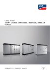
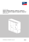
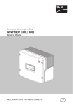
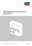
Central Inverter SUNNY CENTRAL Inverters of the HE-20 and CP Series Unpacking and Transport Manual SCxxxCP_HE20-AP-IEN114110 | 98-4104310 | Version 1.0 EN SMA Solar Technology AG Table of Contents Table of Contents 1 Information on this Manual. . . . . . . . . . . . . . . . . . . . . . . . . 5 2 2.1 2.2 Safety . . . . . . . . . . . . . . . . . . . . . . . . . . . . . . . . . . . . . . . . . . 7 Safety Precautions. . . . . . . . . . . . . . . . . . . . . . . . . . . . . . . . . . . . 7 Qualification of Skilled Workers. . . . . . . . . . . . . . . . . . . . . . . . . 7 3 Storage . . . . . . . . . . . . . . . . . . . . . . . . . . . . . . . . . . . . . . . . . 7 4 4.1 Unpacking the Inverter . . . . . . . . . . . . . . . . . . . . . . . . . . . . 8 Unpacking the Inverter after Air and Sea Transport . . . . . . . . . . 8 4.1.1 Checking for Transport Damages . . . . . . . . . . . . . . . . . . . . . . . . . . . . . . . . . . .8 4.1.2 Parts of the Transport Case and Centre of Gravity . . . . . . . . . . . . . . . . . . . . . .9 4.1.3 Symbols on the Transport Case . . . . . . . . . . . . . . . . . . . . . . . . . . . . . . . . . . 10 4.1.4 Removing the Transport Case . . . . . . . . . . . . . . . . . . . . . . . . . . . . . . . . . . . . 11 4.1.5 Removing the Transport Protection Cover . . . . . . . . . . . . . . . . . . . . . . . . . . . 12 4.1.6 Unscrewing the Inverter from the Wooden Pallet . . . . . . . . . . . . . . . . . . . . . 13 4.2 Unpacking the Inverter after Carriage by Land . . . . . . . . . . . . 14 4.2.1 Removing the Transport Protection Cover . . . . . . . . . . . . . . . . . . . . . . . . . . . 14 4.2.2 Removing the Packing Bands . . . . . . . . . . . . . . . . . . . . . . . . . . . . . . . . . . . . 14 4.2.3 Removing the Shipping Packaging . . . . . . . . . . . . . . . . . . . . . . . . . . . . . . . . 15 5 5.1 5.2 5.3 Transporting the Inverter. . . . . . . . . . . . . . . . . . . . . . . . . . 16 Safety during Transport. . . . . . . . . . . . . . . . . . . . . . . . . . . . . . . 16 Centre of Gravity of the Inverter . . . . . . . . . . . . . . . . . . . . . . . . 16 Transporting the Inverter with Transport Case. . . . . . . . . . . . . . 17 5.3.1 Transporting the Transport Case using a Crane Fork . . . . . . . . . . . . . . . . . . 17 5.3.2 Transporting the Transport Case using a Forklift Truck . . . . . . . . . . . . . . . . . 17 5.3.3 Transporting the Transport Case using a Crane . . . . . . . . . . . . . . . . . . . . . . 18 5.3.4 Transporting the Transport Case by Pulling. . . . . . . . . . . . . . . . . . . . . . . . . . 19 Unpacking and Transport Manual SCxxxCP_HE20-AP-IEN114110 3 Table of Contents SMA Solar Technology AG 5.4 Transporting the Inverter without Transport Packaging . . . . . . . 20 5.4.1 Transporting the inverter using a crane fork . . . . . . . . . . . . . . . . . . . . . . . . . 20 5.4.2 Transporting the Inverter using a Forklift Truck . . . . . . . . . . . . . . . . . . . . . . . 20 5.4.3 Transporting the Inverter using a Pallet Truck . . . . . . . . . . . . . . . . . . . . . . . . 21 5.4.4 Transporting the Inverter using a Crane . . . . . . . . . . . . . . . . . . . . . . . . . . . . 21 5.4.5 Transporting the Sunny Central HE using a Crane . . . . . . . . . . . . . . . . . . . . 27 6 6.1 6.2 6.3 Unpacking the Inverter Components . . . . . . . . . . . . . . . . 28 Design of the Inverter . . . . . . . . . . . . . . . . . . . . . . . . . . . . . . . . 28 Position of the Keys . . . . . . . . . . . . . . . . . . . . . . . . . . . . . . . . . . 28 Unpacking the Filter Plate and Kick Plates . . . . . . . . . . . . . . . . 29 6.3.1 Unpacking the Filter Plate and Kick Plates of the Sunny Central CP . . . . . . . . . . . . . . . . . . . . . . . . . . . . . . . . . . . . . . . . . . . . . 29 6.3.2 Unpacking the Kick Plates of the Sunny Central HE . . . . . . . . . . . . . . . . . . . 29 6.4 6.5 Unpacking the Accessories . . . . . . . . . . . . . . . . . . . . . . . . . . . . 29 Removing the Touch Display Packaging . . . . . . . . . . . . . . . . . . 30 7 Scope of Delivery . . . . . . . . . . . . . . . . . . . . . . . . . . . . . . . . 31 8 Transport Packaging Dimensions . . . . . . . . . . . . . . . . . . . 33 9 Contact . . . . . . . . . . . . . . . . . . . . . . . . . . . . . . . . . . . . . . . . 34 4 SCxxxCP_HE20-AP-IEN114110 Unpacking and Transport Manual SMA Solar Technology AG 1 1 Information on this Manual Information on this Manual Validity This manual applies to the following device types: • SC 500HE (SC 500HE-20) • SC 630HE (SC 630HE-20) • SC 720HE (SC 720HE-20) • SC 760HE (SC 760HE-20) • SC 800HE (SC 800HE-20) • SC 500CP • SC 630CP • SC 720CP • SC 760CP • SC 800CP Target Group This manual is intended for skilled persons. Only qualified personnel with the relevant skills are allowed to perform the tasks set forth in this manual (see section 2.2 "Qualification of Skilled Workers", page 7). Additional Information Additional information is available at www.SMA.de/en. Document Title Document Type Installation Requirements - Important information on transportation Technical Information and installation for Sunny Central 500HE/630HE/720HE/ 760HE/800HE Installation Requirements - Important information on transportation Technical Information and installation for Sunny Central 500CP/630CP/720CP/ 760CP/800CP Unpacking and Transport Manual SCxxxCP_HE20-AP-IEN114110 5 SMA Solar Technology AG 1 Information on this Manual Symbols Symbol Explanation %"/(&3 Indicates a hazardous situation which, if not avoided, will result in death or serious injury. 8"3/*/( Indicates a hazardous situation which, if not avoided, could result in death or serious injury. $"65*0/ Indicates a hazardous situation which, if not avoided, could result in minor or moderate injury. /05*$& Indicates a situation which, if not avoided, can result in property damage. Indicates information that is important for a specific topic or objective, but is not safety-relevant. ☐ Indicates a requirement for meeting a specific goal. ☑ Desired result ✖ A problem that could occur. Nomenclature In this manual, the Sunny Central 500HE/630HE/720HE/760HE/800HE and Sunny Central 500CP/630CP/720CP/760CP/800CP are referred to as inverters. 6 SCxxxCP_HE20-AP-IEN114110 Unpacking and Transport Manual SMA Solar Technology AG 2 2 Safety Safety 2.1 Safety Precautions Inverter damage Information labels on the inverter can be damaged during unpacking and transportation. • Check the information labels on the inverter for damage after unpacking and transportation. • Replace any damaged information label. Order new information labels from the SMA Service Line (see 9 "Contact", page 34). 2.2 Qualification of Skilled Workers The tasks described in this manual may only be performed by skilled persons. Skilled persons must have the following qualifications: • Knowledge of and adherence to this manual and all safety precautions 3 Storage /05*$& Penetrating moisture can damage the inverter. • Do not store the inverter in the transport case for longer than 6 months. • Close the inverter before storage. • Only store in a dry, covered location. Ensure that the IP21 degree of protection requirements are met. • The temperature at the storage location must be between ‒20°C ... +50°C. /05*$& An uneven surface can damage the frame construction. • The surface must be suitable for the weight of the inverter of 1 900 kg. • The unevenness of the surface must be lower than 0.25%. Unpacking and Transport Manual SCxxxCP_HE20-AP-IEN114110 7 4 Unpacking the Inverter 4 SMA Solar Technology AG Unpacking the Inverter 4.1 Unpacking the Inverter after Air and Sea Transport 4.1.1 Checking for Transport Damages Two impact indicators are affixed to the transport case to aid with checking for transport damages. The impact indicators show whether the inverter has suffered an impact during transport that could have damaged the inverter. Figure 1: Impact indicators • Check the impact indicators upon delivery. How the impact indicator shows irregular transport of the transport case is either displayed on the impact indicator or in an impact indicator manual included in the delivery. 8 SCxxxCP_HE20-AP-IEN114110 Unpacking and Transport Manual SMA Solar Technology AG 4 Unpacking the Inverter 4.1.2 Parts of the Transport Case and Centre of Gravity The inverter is packed in a transport case for air and sea transport. The transport case is made up of 6 parts. • Front panel • Back panel • Left-hand side panel • Right-hand side panel • Base • Roof Figure 2: Transport case Unpacking and Transport Manual SCxxxCP_HE20-AP-IEN114110 9 4 Unpacking the Inverter SMA Solar Technology AG 4.1.3 Symbols on the Transport Case The following symbols are affixed to the transport case: Symbol Designation Transport the transport case with this side above. The transport case content is fragile. Do not use any sharp tools to open the transport case. Do not place anything on the transport case. Transport case centre of gravity Position for transport using a crane. 10 SCxxxCP_HE20-AP-IEN114110 Unpacking and Transport Manual SMA Solar Technology AG 4 Unpacking the Inverter 4.1.4 Removing the Transport Case $"65*0/ Danger of crushing due to heavy, bulky transport case side panels. The transport case side panels and roof are heavy and bulky. • Always dismantle the side panels and the roof with 2 people. The transport case is closed with Torx screws. On the right-hand side panel of the transport case is a flap, behind which a bit is stored. Preparing the tool: 1. Push the flap to the left. 2. Pull out the bag with bit from the flap. 3. Take the bit out of the bag. 4. Insert the bit into the power screwdriver. ☑ The tool is prepared. Unpacking and Transport Manual SCxxxCP_HE20-AP-IEN114110 11 SMA Solar Technology AG 4 Unpacking the Inverter Removing the transport case parts: The screw points on the transport case are marked in red. Figure 3: Identification of the screw points 1. Remove the Torx screws from the roof. 2. Remove the roof. 3. Remove the Torx screws from the back panel. 4. Remove the back panel. 5. Remove the Torx screws from the front panel. 6. Remove the front panel. 7. Remove the Torx screws from the right-hand side panel. 8. Remove the right-hand side panel. 9. Remove the Torx screws from the left-hand side panel. 10. Remove the left-hand side panel. ☑ The transport case has been removed. 4.1.5 Removing the Transport Protection Cover 1. Open the transport protection cover using a knife or a pair of scissors. 2. Remove the transport protection cover from the inverter. 3. Cut through the adhesive tapes on the shipping carton for the filter plates. Hold the shipping carton tightly whilst doing so. 12 SCxxxCP_HE20-AP-IEN114110 Unpacking and Transport Manual SMA Solar Technology AG 4 Unpacking the Inverter 4.1.6 Unscrewing the Inverter from the Wooden Pallet 8"3/*/( Danger of crushing through the inverter tipping Once the screws have been removed the inverter is no longer secured and can tip from the pallet during transport. • Do not transport the inverter on the pallet once the screws have been removed. The inverter is attached to the wooden pallet with screws. Figure 4: Position of the screws on the Sunny Central of the HE production series Figure 5: Position of the screws on the Sunny Central of the CP production series • Remove the screws from the wooden pallet. Unpacking and Transport Manual SCxxxCP_HE20-AP-IEN114110 13 SMA Solar Technology AG 4 Unpacking the Inverter 4.2 Unpacking the Inverter after Carriage by Land 4.2.1 Removing the Transport Protection Cover 1. Open the transport protection cover using a knife or a pair of scissors. 2. Remove the transport protection cover from the inverter. 4.2.2 Removing the Packing Bands $"65*0/ Cuts due to the packing bands springing out The packing bands are under tension and spring out when cut. • Wear personal protective equipment. • Maintain a safe distance from the packing bands. For surface transport of the inverter the shipping packaging is attached to the wooden pallet using packing bands. Figure 6: Packing bands on the packed inverter 1. Cut through the packing bands using a knife. 2. Remove the packing bands. 14 SCxxxCP_HE20-AP-IEN114110 Unpacking and Transport Manual SMA Solar Technology AG 4 Unpacking the Inverter 4.2.3 Removing the Shipping Packaging $"65*0/ Crushing through falling shipping carton for the filter plate Shipping carton can fall when being removed from the inverter. • Wear personal protective equipment. • Hold the shipping carton tightly when removing. /05*$& Damage to the inverter finishing or display through sharp objects The inverter finishing or display can be damaged during opening of the shipping packaging using a sharp object. Damage to the inverter finishing or the display • Do not cut deeply into the shipping packaging. 1. Cut through the adhesive tapes on the shipping carton for the filter plates. Hold the shipping carton tightly whilst doing so. 2. Remove the shipping carton for the filter plates from the wooden pallet of the inverter. 3. Remove the cover of the inverter shipping packaging. 4. Remove the shipping packaging: • For the Sunny Central HE, cut through the adhesive tapes using a knife or a pair of scissors and remove the shipping packaging from the Sunny Central. • For the Sunny Central CP, remove the 6 clips from the holes in the shipping packaging and remove the shipping packaging from the Sunny Central. 5. Unscrew the inverter from the wooden pallet (see section 4.1.6 "Unscrewing the Inverter from the Wooden Pallet", page 13). Unpacking and Transport Manual SCxxxCP_HE20-AP-IEN114110 15 5 Transporting the Inverter 5 SMA Solar Technology AG Transporting the Inverter 5.1 Safety during Transport Crushing Danger of crushing through tipping, falling or swinging of raised or hanging Sunny Central The inverter can tip or fall as a result of careless or too-fast lifting and transporting. • Always transport the inverter as close to the floor as possible. • Use all attachment points for transporting. • Only use transport material and lifting tools that are designed for the weight of the inverter of 1 900 kg. • Avoid fast and jerky movements during transport. • Always maintain a sufficient safety distance from the inverter during transport. Inverter damage Damage to the inverter due to inappropriate transport. • Only place the inverter on secure, level surfaces. Uneven surfaces can lead to the inverter buckling and the doors no longer closing correctly. As a result moisture and dust can penetrate the interior of the inverter. 5.2 Centre of Gravity of the Inverter The centre of gravity of the inverter is not in the middle of the inverter. Take this into consideration during transport. The centre of gravity of the inverter is marked with the centre of gravity symbol on the transport case, the packaging and on the enclosure. Figure 7: 16 Centre of gravity symbol SCxxxCP_HE20-AP-IEN114110 Unpacking and Transport Manual SMA Solar Technology AG 5 Transporting the Inverter 5.3 Transporting the Inverter with Transport Case 5.3.1 Transporting the Transport Case using a Crane Fork Requirements: ☐ The crane and crane fork are designed for the weight of the inverter. ☐ The crane fork is correctly connected to the crane. 1. Drive the forks of the crane fork under the transport case at the positions marked. Observe the centre of gravity of the transport case when doing so. 2. Slowly lift the transport case using the crane fork. 3. Secure the transport case against tipping. 4. Transport the transport case to the location of installation and place on a fortified and level surface. 5.3.2 Transporting the Transport Case using a Forklift Truck Requirements: ☐ The forklift truck is designed for the weight of the inverter. 1. Drive the forklift truck completely under the transport case at the marked positions. When doing so observe the centre of gravity of the transport case and drive the forklift truck completely under the transport case. 2. Slowly lift the transport case. 3. Secure the transport case against tipping. 4. Transport the transport case to the location of installation and place on a fortified and level surface. Unpacking and Transport Manual SCxxxCP_HE20-AP-IEN114110 17 SMA Solar Technology AG 5 Transporting the Inverter 5.3.3 Transporting the Transport Case using a Crane Requirements: ☐ The crane and lifting gear are designed for the weight of the inverter. ☐ The lifting gear is correctly connected to the crane. ☐ The inverter roof is dismantled. 1. Push the crane chains under the transport case at the positions marked. Observe the centre of gravity of the transport case when doing so. 2. Hang the crane chains in the crane hook. 3. Slowly lift the crane hook until the lifting gear is under tension. 4. Ensure that the lifting gear is correctly attached. 5. Lift the transport case slightly. 6. Transport the transport case as close to the floor as possible. 7. Transport the transport case to the installation site and place on a fortified and level surface. 18 SCxxxCP_HE20-AP-IEN114110 Unpacking and Transport Manual SMA Solar Technology AG 5 Transporting the Inverter 5.3.4 Transporting the Transport Case by Pulling /05*$& Damage to the inverter due to inappropriate transport Jerking of the inverter when pulling the transport case over uneven floors. • Only pull the transport case over even floors. • Pull the transport case slowly. Eyes are attached below the right-hand and left-hand side panels for transporting the transport case. Figure 8: Transport eyes 1. Attach transport hooks to the eyes. 2. Pre-tense the transport material. 3. Transport the transport case. Unpacking and Transport Manual SCxxxCP_HE20-AP-IEN114110 19 SMA Solar Technology AG 5 Transporting the Inverter 5.4 Transporting the Inverter without Transport Packaging 5.4.1 Transporting the inverter using a Crane Fork Requirements: ☐ The crane and crane fork are designed for the weight of the inverter. ☐ The crane fork is correctly connected to the crane. 1. Drive the forks of the crane fork from the front side or from the back side of the inverter under the inverter. When doing so observe the centre of gravity of the inverter and drive with the forks completely under the inverter. SUN NY CEN TRAL 800CP SMA 2. Slowly lift the inverter using the crane fork. 3. Transport the inverter to the location of installation and place on a fortified and level surface. 5.4.2 Transporting the Inverter using a Forklift Truck Requirements: ☐ The forklift truck is designed for the weight of the inverter. 1. Drive the forklift truck from the front side or from the rear side of the inverter under the inverter. When doing so observe the centre of gravity of the inverter and drive with forklift truck completely under the inverter. 2. Secure the inverter against tipping, e.g. using tension belts. 3. Lift the inverter slightly. 4. Transport the inverter to the location of installation and place on a fortified and level surface. 20 SCxxxCP_HE20-AP-IEN114110 Unpacking and Transport Manual SMA Solar Technology AG 5 Transporting the Inverter 5.4.3 Transporting the Inverter using a Pallet Truck Requirements: ☐ The pallet truck is designed for the weight of the inverter. 1. If the inverter is to be transported on a wooden pallet, drive the pallet truck from the side under the inverter. 2. If the inverter is to be transported without a wooden pallet, only drive the pallet truck from the front side of the inverter cabinet under the inverter. Ensure that the kick plates of the inverter are not damaged by the forks whilst doing so. 3. Secure the inverter against tipping, e.g. using tension belts. 4. Lift the inverter slightly. 5. Transport the inverter to the location of installation and place on a fortified and level surface. 5.4.4 Transporting the Inverter using a Crane Transporting the Sunny Central CP with a crane Removing the inverter roof $"65*0/ Danger of crushing due to heavy, bulky roof. The inverter roof weighs 30 kg and is bulky. Trying to move the roof on your own can cause crushing. • 2 people are necessary for the removal of the roof. /05*$& Property damage by pulling out the PE cable. The roof is connected to the inverter by a PE cable. • When dismantling the panels, ensure that the PE cable is not damaged. Unpacking and Transport Manual SCxxxCP_HE20-AP-IEN114110 21 5 Transporting the Inverter SMA Solar Technology AG 1. Remove the screws of the right-hand ventilation grid. 2. Pull the lower side of the right-hand ventilation grid to the front. Remove the ventilation grid. 3. Remove the screws of the left-hand ventilation grid. 22 SCxxxCP_HE20-AP-IEN114110 Unpacking and Transport Manual SMA Solar Technology AG 5 Transporting the Inverter 4. Pull the lower side of the left-hand ventilation grid to the front. Remove the ventilation grid. 5. Pull the front edge of the roof to the front and push upwards. 6. Push the roof slightly to the rear. In doing so you push the roof out of the rails. 7. Remove the PE cable from the inverter. 8. Remove the inverter roof and place on a suitable surface. Unpacking and Transport Manual SCxxxCP_HE20-AP-IEN114110 23 SMA Solar Technology AG 5 Transporting the Inverter Transporting the Inverter Requirements: ☐ The crane and lifting gear are designed for the weight of the inverter. ☐ The lifting gear is correctly connected to the crane. ☐ The inverter roof is dismantled. 1. Hang the lifting gear in all 4 crane eyes on the inverter. 2. Slowly lift the crane hook until the lifting gear is under tension. 3. Ensure that the lifting gear is correctly attached. 4. Lift the inverter slightly. 5. Transport the inverter as close to the floor as possible. 6. Transport the inverter to the installation site and place on a fortified and level surface. Mounting the inverter roof $"65*0/ Danger of crushing due to heavy, bulky roof The inverter roof weighs 30 kg and is bulky. Trying to move the roof on your own can cause crushing. • Move the roof with at least 2 people. 1. Lay the roof on the inverter. 24 SCxxxCP_HE20-AP-IEN114110 Unpacking and Transport Manual SMA Solar Technology AG 5 Transporting the Inverter 2. Screw the PE cable onto the inverter (torque: 14.2 Nm). 3. Push the roof into the rail on the inverter and pull to the front. 4. Push the roof downwards. 5. Insert the left-hand ventilation grid. Unpacking and Transport Manual SCxxxCP_HE20-AP-IEN114110 25 5 Transporting the Inverter SMA Solar Technology AG 6. Screw the left-hand ventilation grid into place (torque: 20 Nm). 7. Insert the right-hand ventilation grid. 8. Screw the right-hand ventilation grid into place (torque: 20 Nm). 26 SCxxxCP_HE20-AP-IEN114110 Unpacking and Transport Manual SMA Solar Technology AG 5 Transporting the Inverter 5.4.5 Transporting the Sunny Central HE using a Crane 1. Hang the load hooks of the steel cables, steel chains or the shackles of the lifting hook in all 4 crane eyes on the inverter. 2. If the inverter is to be transported using the crane fork, drive the crane fork on the front side under the inverter. HE 3. Slowly lift the crane hook until the steel cables or steel chains are under tension. 4. Ensure that all steel cables and load hooks or load beams and shackles are correctly attached. 5. Lift the inverter slightly. 6. Transport the inverter to the location of installation and place on a fortified and level surface. Unpacking and Transport Manual SCxxxCP_HE20-AP-IEN114110 27 6 Unpacking the Inverter Components 6 SMA Solar Technology AG Unpacking the Inverter Components 6.1 Design of the Inverter Figure 9: Design of the inverter using a Sunny Central CP as an example Position A B C D Designation Inverter cabinet Connection cabinet Display Front panel of the connection cabinet 6.2 Position of the Keys /05*$& Damage to the inverter through manipulation after unauthorised access If the key remains in the door lock, the inverter can be opened by unauthorised persons. • Remove the keys from the door locks and from the key switch. • Store the keys in a safe place. The keys are in a bag attached to the door of the connection cabinet. The bag contains: • 2 keys for the key switch under the display • 2 keys for the inverter doors 28 SCxxxCP_HE20-AP-IEN114110 Unpacking and Transport Manual SMA Solar Technology AG 6 Unpacking the Inverter Components 6.3 Unpacking the Filter Plate and Kick Plates 6.3.1 Unpacking the Filter Plate and Kick Plates of the Sunny Central CP 1. Open the filter plate shipping carton. 2. Remove the filter plate and kick plates. 6.3.2 Unpacking the Kick Plates of the Sunny Central HE The Sunny Central HE kick plates are stored in the connection cabinet. 6.4 Unpacking the Accessories The accessories shipping carton is stored in the inverter connection cabinet. 1. Remove the screws of the front panel of the connection cabinet. 2. Pull off the front panel to the front. 3. Cut through and remove the cable tie used to attach the accessories shipping carton in the inverter. 4. Remove the shipping carton from the connection cabinet. 5. Unpack the accessories. 6. Remount the front panel of the connection cabinet Unpacking and Transport Manual SCxxxCP_HE20-AP-IEN114110 29 6 Unpacking the Inverter Components SMA Solar Technology AG 6.5 Removing the Touch Display Packaging /05*$& Damage to the touch display through sharp objects The touch display can be scratched by sharp objects during removal of the packaging. • Only remove the display packaging once all assembly work and installation work on the inverter is finished. 1. Remove the adhesive tapes. 2. For the Sunny Central CP, push the cover upwards. 3. Pull the protective foil from the display. 30 SCxxxCP_HE20-AP-IEN114110 Unpacking and Transport Manual SMA Solar Technology AG 7 7 Scope of Delivery Scope of Delivery Check the delivery for completeness and any visible external damage. In the event of an incomplete delivery or damage, contact your specialty retailer. Sunny Central CP Figure 10: Component parts of the delivery Position Quantity Designation A 1 Sunny Central B 1 Installation manual, user manual, circuit diagram, commissioning report C 1 Air baffle with filter frame D 5 Kick plate E 1 LV/HRC fuse handle** F 1 Cleaning cloth G 34/6* Screw H 34/6* Nut I 68/12* Fender washer K 68/12* Spring washer L 80 Cable tie M 3 Rubber seal (9.5 mm ... 16 mm) * Quantity for the Optiprotect order option ** With DC fuse order option Unpacking and Transport Manual SCxxxCP_HE20-AP-IEN114110 31 SMA Solar Technology AG 7 Scope of Delivery Sunny Central HE Figure 11: Component parts of the delivery Position Quantity Designation A 1 Sunny Central B 1 Installation manual, user manual, circuit diagram, commissioning report C 6 Kick plate D 1 LV/HRC fuse handle* E 1 Cleaning cloth F 34 Screw G 34 Nut H 68 Fender washer I 68 Spring washer K 80 Cable tie L 3 Rubber seal (9.5 mm ... 17 mm) * With the DC fuses order option, the LV/HRC fuse handle is to be found in the inside of the right-hand door of the connection cabinet. 32 SCxxxCP_HE20-AP-IEN114110 Unpacking and Transport Manual SMA Solar Technology AG 8 8 Transport Packaging Dimensions Transport Packaging Dimensions The dimensions are given in width x height x depth. Sunny Central HE Transport case 2 900 mm x 1 150 mm x 2 580 mm Wooden pallet 2 890 x 1 115 x 179 mm Shipping packaging Lid Transport protection cover 4 659 x 2 295 x 5 mm 2 635 x 1 060 x 100 mm 3 600 x 1 050 x 2 300 mm Weight of the inverter 1 900 kg Weight of the packed inverter with transport case 2 280 kg Sunny Central CP Transport case 2 900 mm x 1 150 mm x 2 580 mm Wooden pallet 2 890 x 1 115 x 179 mm Shipping packaging Lid Transport protection cover 4 626 x 2 295 x 5 mm 3 263 x 1 649 x 300 mm 3 600 x 1 050 x 2 300 mm Weight of the inverter 1 800 kg Weight of the packed inverter with transport case 2 180 kg Unpacking and Transport Manual SCxxxCP_HE20-AP-IEN114110 33 SMA Solar Technology AG 9 Contact 9 Contact If you have technical problems concerning our products, contact the SMA Service Line. We require the following information in order to provide you with the necessary assistance: • Device type and serial number of the inverter (see the inverter installation manual). SMA Solar Technology AG Sonnenallee 1 34266 Niestetal www.SMA.de SMA Service Line Tel. +49 561 9522 299 Fax: +49 561 9522 3299 E‑Mail: [email protected] 34 SCxxxCP_HE20-AP-IEN114110 Unpacking and Transport Manual SMA Solar Technology AG Legal Restrictions The information contained in this document is the property of SMA Solar Technology AG. Publishing its content, either partially or in full, requires the written permission of SMA Solar Technology AG. Any internal company copying of the document for the purposes of evaluating the product or its correct implementation is allowed and does not require permission. Exclusion of liability The general terms and conditions of delivery of SMA Solar Technology AG shall apply. The content of these documents is continually checked and amended, where necessary. However, discrepancies cannot be excluded. No guarantee is made for the completeness of these documents. The latest version is available online at www.SMA.de or from the usual sales channels. Guarantee or liability claims for damages of any kind are excluded if they are caused by one or more of the following: • Damages during transportation • Improper or inappropriate use of the product • Operating the product in an unintended environment • Operating the product whilst ignoring relevant, statutory safety regulations in the deployment location • Ignoring safety warnings and instructions contained in all documents relevant to the product • Operating the product under incorrect safety or protection conditions • Altering the product or supplied software without authority • The product malfunctions due to operating attached or neighboring devices beyond statutory limit values • In case of unforeseen calamity or force majeure The use of supplied software produced by SMA Solar Technology AG is subject to the following conditions: • SMA Solar Technology AG rejects any liability for direct or indirect damages arising from the use of software developed by SMA Solar Technology AG. This also applies to the provision or non-provision of support activities. • Supplied software not developed by SMA Solar Technology AG is subject to the respective licensing and liability agreements of the manufacturer. SMA Factory Warranty The current guarantee conditions come enclosed with your device. These are also available online at www.SMA.de and can be downloaded or are available on paper from the usual sales channels if required. Trademarks All trademarks are recognized even if these are not marked separately. Missing designations do not mean that a product or brand is not a registered trademark. The Bluetooth® word mark and logos are registered trademarks owned by Bluetooth SIG, Inc. and any use of such marks by SMA Solar Technology AG is under license. SMA Solar Technology AG Sonnenallee 1 34266 Niestetal Germany Tel. +49 561 9522-0 Fax +49 561 9522-100 www.SMA.de E-Mail: [email protected] © 2004 to 2012 SMA Solar Technology AG. All rights reserved Unpacking and Transport Manual SCxxxCP_HE20-AP-IEN114110 35 4."4PMBS5FDIOPMPHZ XXX4."4PMBSDPN 4."4PMBS5FDIOPMPHZ"( XXX4."EF 4.""NFSJDB--$ XXX4.""NFSJDBDPN 4."5FDIOPMPHZ"VTUSBMJB1UZ-UE XXX4.""VTUSBMJBDPNBV 4."#FOFMVY413XXX4."#FOFMVYDPN 4."#FJKJOH$PNNFSDJBM$P-UE XXX4."$IJOBDPN 4."$[FDI3FQVCMJDTSP XXX4."$[FDIDPN 4."'SBODF4"4 XXX4."'SBODFDPN 4.")FMMBT"& XXX4.")FMMBTDPN 4."*C©SJDB5FDOPMPHB4PMBS4- XXX4."*CFSJDBDPN 4."*UBMJB4SM XXX4."*UBMJBDPN 4."5FDIOPMPHZ,PSFB$P-UE XXX4.",PSFBDPN