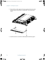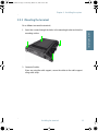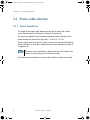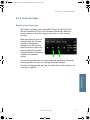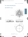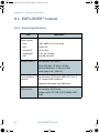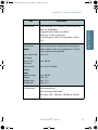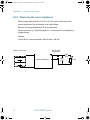
1
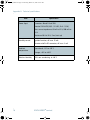
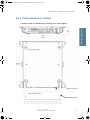
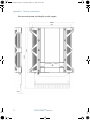
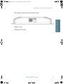
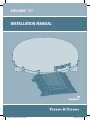
Explorer® 727
Installation manual
17865-TT Installation manual A5.indd 1
03/04/08 13:17:58
E727_IM.book Page i Thursday, March 27, 2008 10:01 AM
Thrane & Thrane A/S
EXPLORER®727
Installation manual
Document number: TT98-126844-B
Release date: March 27, 2008
E727_IM.book Page ii Thursday, March 27, 2008 10:01 AM
Information in this document is subject to change without notice and does not represent
a commitment on the part of Thrane & Thrane A/S. We recommend downloading the
latest version of the manual from the Thrane & Thrane A/S web site www.thrane.com.
Copyright © 2008 Thrane & Thrane A/S. All rights reserved.
Trademark acknowledgements
•
Thrane & Thrane is a registered trademark of Thrane & Thrane A/S in the European
Union and the United States.
•
EXPLORER is a registered trademark of Thrane & Thrane A/S in the European Union
and the United States.
•
Windows and Outlook are registered trademarks of Microsoft Corporation in the
United States and other countries.
•
Inmarsat is a registered trademark of International Maritime Satellite Organisation
(IMSO) and is licensed by IMSO to Inmarsat Limited and Inmarsat Ventures plc.
•
Inmarsat’s product names are trademarks or registered trademarks of Inmarsat.
•
Other product and company names mentioned in this manual may be trademarks or
trade names of their respective owners.
Company addresses
www.thrane.com
Denmark
Company headquarters
Denmark
Thrane & Thrane A/S
Lundtoftegårdsvej 93 D
DK-2800 Kgs. Lyngby
Denmark
Thrane & Thrane Aalborg A/S
Porsvej 2
DK-9200 Aalborg SV
Denmark
USA
China
Thrane & Thrane, Inc.
509 Viking Drive, Suites K, L and M
Virginia Beach, VA 23452
USA
Thrane & Thrane Shanghai
Unit 602 - Building 4,
289 Bisheng Rd.
Zhangjiang High-tech Park,
Pudong
201204 Shanghai
P. R. China
E727_IM.book Page iii Thursday, March 27, 2008 10:01 AM
Safety summary
1
The following general safety precautions must be observed during all
phases of operation, service and repair of this equipment. Failure to comply
with these precautions or with specific warnings elsewhere in this manual
violates safety standards of design, manufacture and intended use of the
equipment. Thrane & Thrane A/S assumes no liability for the customer's
failure to comply with these requirements.
Observe marked areas
Under extreme heat conditions do not touch
areas of the terminal or antenna that are
marked with this symbol, as it may result in
injury.
Microwave radiation hazards
During transmission the antenna in this system radiates microwave power.
This radiation may be hazardous to humans close to the antenna. When the
system is powered, make sure that nobody gets closer than the
recommended minimum safety distance.
The minimum safety distance is 1 m to the side
and above the antenna when the EXPLORER 727
is powered. The safety distance of 1 m does not
apply directly below the antenna, as the
radiation forms a hemisphere above the antenna.
Service
User access to the interior of the system units is prohibited. Only a
technician authorized by Thrane & Thrane A/S may perform service - failure
to comply with this rule will void the warranty.
Do not service or adjust alone
Do not attempt internal service or adjustments unless another person,
capable of rendering first aid resuscitation, is present.
iii
E727_IM.book Page iv Thursday, March 27, 2008 10:01 AM
Power supply
The voltage range is 10.5 - 32 V DC; 14 A - 5.5 A. Be aware of high start-up
peak current: 20 A at 24 V, 5 ms.
Do not operate in an explosive atmosphere
Do not operate the equipment in the presence of flammable gases or fumes.
Operation of any electrical equipment in such an environment constitutes a
definite safety hazard.
Keep away from live circuits
Operating personnel must not remove equipment covers. Component
replacement and internal adjustment must be made by qualified
maintenance personnel. Do not replace components with the power cable
connected. Under certain conditions, dangerous voltages may exist even
with the power cable removed. To avoid injuries, always disconnect power
and discharge circuits before touching them.
Install and use the antenna with care
Thrane & Thrane A/S assumes no liability for any damage caused by the
antenna falling off the vehicle or stressing the mounting base. It is the
responsibility of the customer to ensure a safe and correct installation of the
antenna. The instructions in this manual are only guidelines.
Failure to comply with the rules above will void the warranty!
iv
E727_IM.book Page v Thursday, March 27, 2008 10:01 AM
About the manual
2
Intended readers
This is an installation manual for the EXPLORER 727 system. The
readers of the manual include installers of the system and service
personnel. Personnel installing or servicing the system must be
properly trained and authorized by Thrane & Thrane. It is
important that you observe all safety requirements listed in the
beginning of this manual, and install the system according to the
guidelines in this manual.
Manual overview
Note that this manual does not cover general use of the system nor
does it cover how to use the IP handset that comes with the
system. For this information, refer to the user manual for this
system and the user manual for the IP handset, both listed in the
next section.
This manual has the following chapters:
•
System units contains a short description of each main unit in
the system.
•
Installing the system describes where to place the system units,
how to mount them, distance to other equipment etc.
•
Connecting power explains how to connect the terminal to
power and gives recommendations for cables.
•
Hardware interfaces describes each interface on the terminal
and shows pin-out for the connectors.
•
Starting up the system explains how to insert the SIM card,
power up the system and enter the PIN. It also gives a short
overview of how to use the system.
•
Troubleshooting describes the function of the Reset button and
the light indicators on the terminal. It also describes event
messages that may appear in the web interface.
v
E727_IM.book Page vi Thursday, March 27, 2008 10:01 AM
This manual may not always reflect the latest software
functionality of your EXPLORER system. To obtain the latest version
of the manual, please enter the Thrane & Thrane web site
www.thrane.com and download the latest version, or acquire it
from your distributor.
Related documents
The below list shows the documents related to this manual and to
the EXPLORER 727 system.
Title and description
Document
number
EXPLORER 727 User Manual
TT98-126882
Explains how to set up and use the EXPLORER
system.
EXPLORER 727 Quick Guide
TT98-126881
A short guide to the most important functions
of the EXPLORER systems.
EXPLORER 727 Getting Started
TT98-126880
Explains how to start up your EXPLORER 727
system and make the first call or data session.
Thrane & Thrane IP Handset, User Manual
Explains the features and functions of the
Thrane & Thrane IP handset. The IP handset
works as a standard IP handset, but also
serves as a user interface for the EXPLORER
systems.
vi
TT98-126059
E727_IM.book Page vii Thursday, March 27, 2008 10:01 AM
Typography
In this manual, typography is used as indicated below:
Bold is used for the following purposes:
•
To emphasize words.
Example: “Do not touch the antenna”.
•
To indicate what the user should select in the user interface.
Example: “Select Settings > LAN”.
Italic is used to emphasize the paragraph title in crossreferences.
Example: “For further information, see Connecting Cables on
page...”.
vii
E727_IM.book Page viii Thursday, March 27, 2008 10:01 AM
viii
E727_IM.book Page ix Thursday, March 27, 2008 10:01 AM
Table of contents
Chapter 1
Chapter 2
System units
1.1
Introduction ............................................................... 1
1.2
EXPLORER® terminal ........................................... 1
1.3
EXPLORER®727 antenna ....................................2
1.4
IP handset and cradle ................................................3
Installing the system
2.1
Unpacking .................................................................5
2.2 Placing the antenna ...................................................6
2.3 Installing the antenna ................................................7
2.4 Placing the terminal .................................................16
2.5 Installing the terminal ..............................................17
Chapter 3
Connecting power
3.1
Power source ............................................................21
3.2 Power cable selection .............................................. 22
3.3 To connect power ....................................................26
Chapter 4
Hardware interfaces
4.1
The connector panel ................................................29
4.2 Antenna interface on terminal .................................30
4.3 DC power input .........................................................31
4.4 Analog Phone/Fax interface .....................................33
4.5 ISDN interface ..........................................................34
4.6 LAN interface ...........................................................36
ix
E727_IM.book Page x Thursday, March 27, 2008 10:01 AM
Table of contents
4.7 Discrete I/O interface ................................................38
Chapter 5
Starting up the system
5.1
Using the SIM card ................................................... 41
5.2 Powering the system ................................................43
5.3 Entering the SIM PIN for the terminal ......................45
5.4 Operating the system ...............................................47
Chapter 6
Troubleshooting
6.1
Reset button ............................................................49
6.2 Status signaling .......................................................52
6.3 Logging of events .................................................... 58
App. A
Part numbers
A.1 System units ............................................................59
A.2 Spare parts, EXPLORER®727 ............................ 60
A.3 Options and accessories ........................................... 61
App. B
Technical specifications
B.1 Overview ..................................................................63
B.2 EXPLORER®727 antenna ...................................63
B.3 EXPLORER® terminal ........................................ 68
Glossary
.........................................................................................75
Index
.........................................................................................79
x
E727_IM.book Page 1 Thursday, March 27, 2008 10:01 AM
11111
Chapter 1
System units
System units
1
1.1 Introduction
The basic system consists of three units: The terminal, the antenna and the IP
handset with cradle.
1.2 EXPLORER® terminal
The terminal, which contains the primary electronic parts, is designed for wall
or desktop installation.
The terminal supplies 23.0 - 30.0 V DC to the antenna through a single coaxial
cable.
The DC input for the terminal is designed for both 24 V DC and 12 V DC power
supply.
1
E727_IM.book Page 2 Thursday, March 27, 2008 10:01 AM
Chapter 1: System units
1.3 EXPLORER®727 antenna
The EXPLORER 727 antenna is a mechanical tracking antenna, consisting of a
2-axis stabilized antenna with RF-unit, antenna control unit and GPS antenna.
The antenna is dedicated to the Inmarsat BGAN (Broadband Global Area
Network) system and is designed for roof mounting on a vehicle. All
communication between the antenna and terminal passes through a single
coaxial cable.
2
EXPLORER®727 antenna
E727_IM.book Page 3 Thursday, March 27, 2008 10:01 AM
11111
Chapter 1: System units
System units
1.4 IP handset and cradle
1.4.1 Thrane & Thrane IP handset
Besides the normal functions of an IP handset, the Thrane & Thrane IP
handset also provides a user interface for the EXPLORER system. The IP
handset connects to the LAN interface of the terminal, and is power supplied
with Power over Ethernet (PoE) through the LAN interface.
For further information on the IP handset, refer to the user manual for the
Thrane & Thrane IP handset.
IP handset and cradle
3
E727_IM.book Page 4 Thursday, March 27, 2008 10:01 AM
Chapter 1: System units
1.4.2 Thrane & Thrane IP cradle
The IP cradle serves as a holder for the IP handset. It is power supplied from
the terminal using Power over Ethernet (PoE). The cradle connects to the
handset with a coil cord and to the terminal with a standard LAN cable.
4
IP handset and cradle
E727_IM.book Page 5 Thursday, March 27, 2008 10:01 AM
22222
Chapter 2
Installing the system
2
Installing the system
2.1 Unpacking
Unpack your EXPLORER system and check that the following items are
present:
•
TT-3736A EXPLORER terminal
•
TT-3053B EXPLORER 727 antenna
•
TT-3670A IP handset and cradle
•
Basic cable support kit including an I/O connector
•
Power cable
•
Antenna cable
•
LAN cable
•
Installation manual (this manual)
•
Getting Started kit including:
•
Getting Started leaflet
•
Quick Guide
•
EXPLORER 727 CD including electronic versions of User manual,
Installation manual, Quick Guide and Getting Started guide.
Inspect all units and parts for possible transport damage.
Note
For information on how to install the IP handset and cradle, refer to
the user manual for the handset.
5
E727_IM.book Page 6 Thursday, March 27, 2008 10:01 AM
Chapter 2: Installing the system
2.2 Placing the antenna
2.2.1 Obstructions
Obstructions can cause signal degradation.
The amount of degradation depends on the size of the obstruction and the
distance from the antenna. As a rule of thumb any obstruction that subtends
an angle of less than 3° at the antenna has limited effect. The table below
gives a guideline for obstruction sizes that will cause limited degradation.
Distance of Obstruction
Size of Obstruction
3m
16 cm
5m
26 cm
10 m
52 cm
20 m
104 cm
2.2.2 Radiation hazard
The EXPLORER 727 antenna radiates up to 18 dBW EIRP. This translates to a
minimum safety distance of 1 m from the antenna while it is transmitting. Note
that the safety distance applies to a hemisphere above the antenna. The
antenna does not radiate power directly below the antenna.
2.2.3 Interference
Do not place the antenna close to interfering signal sources or receivers. We
recommend that no other antennas are located within three meters of the
antenna. If other equipment is installed near the EXPLORER 727 we
recommend testing the total system by operating all equipment
simultaneously and verifying that there is no interference.
6
Placing the antenna
E727_IM.book Page 7 Thursday, March 27, 2008 10:01 AM
22222
Chapter 2: Installing the system
2.3.1 Antenna cables
Guidelines
A coaxial cable for connection between the antenna and terminal is delivered
with the system. If you need a different cable, make sure that the cable meets
the requirements. Preferably choose one of the cable types in Recommended
antenna cables on page 7.
The maximum allowed RF-loss in the antenna cable is 20 dB at 1660 MHz. This
is to ensure the performance of the system.
Recommended antenna cables
The table below shows recommended cable types and maximum cable lengths
for EXPLORER 727.
Cable Type
Absolute maximum length
RG-223_U-01
14 m
RG-214_U-01
50 m
S-10162-B-11
92 m
Check in the data sheet from the cable supplier that both the RF- attenuation
and the DC-resistance are kept within the maximum specified values:
•
Antenna cable RF-attenuation at 1660 MHz: max. 20 dB incl. connector.
•
Antenna cable modem-attenuation at 54 MHz: max. 4 dB.
Antenna cable modem-attenuation at 36 MHz: max. 3 dB.
•
Antenna cable loop DC-resistance max: 0.6 Ω.
Installing the antenna
7
Installing the system
2.3 Installing the antenna
E727_IM.book Page 8 Thursday, March 27, 2008 10:01 AM
Chapter 2: Installing the system
Also ensure that the specified minimum bending radius is respected. If this is
not the case, the loss in the cable will increase. Check the instruction from the
cable supplier. The bending radius for the coax cable delivered with the
system is min. 110 mm.
2.3.2 Important mounting notes
Line of sight
Place the antenna with free line of sight in all directions to ensure proper
reception of the satellite signal. Do not place the antenna close to large
objects that may block the signal.
After installing and starting up the EXPLORER 727, we recommend checking
the signal strength while driving the vehicle in a 360° circle to ensure a clear
line of sight in all directions.
Condensation
In some cases there will be condensation inside the antenna. Gaskets in the
bottom of the EXPLORER 727 antenna are designed to lead any water away
from the antenna.
Make sure these draining gaskets are not blocked.
Important
Make sure there is always a distance of min. 10 mm between
any part of the antenna bottom and the mounting surface. Use
10 mm spacers (or higher if necessary) at each bolt.
See the drawing in Mounting the antenna directly on the vehicle roof on
page 15.
8
Installing the antenna
E727_IM.book Page 9 Thursday, March 27, 2008 10:01 AM
22222
Chapter 2: Installing the system
Safety
It is the responsibility of the customer to ensure a safe
installation! See guidelines below.
Under normal driving circumstances the magnetic force of the magnetic
mount kit for the antenna should be sufficient to hold the antenna. However,
the magnets may not be able to hold the antenna in place, if:
•
the vehicle is involved in an accident,
•
the magnets are not mounted properly,
•
the roof is not plain or made of a material that will not stick properly to the
magnets,
•
the speed of the vehicle is too high and/or
•
the road is very bumpy.
We recommend mounting the antenna on the roof rails or directly on the roof
instead of using the magnetic mount kit. Make sure that all mounting bolts
and nuts are secured properly, and that the material of the mounting surface
is strong enough to hold the antenna during the intended use.
Installing the antenna
9
Installing the system
Caution!
E727_IM.book Page 10 Thursday, March 27, 2008 10:01 AM
Chapter 2: Installing the system
2.3.3 Mounting the antenna
The antenna can now be installed on the roof of the vehicle with three
stainless steel bolts. You may choose between three methods:
•
Attach the antenna to the roof rails on your vehicle using the dedicated
mounting brackets delivered with your EXPLORER 727 system.
•
Attach the antenna using the magnetic mount kit from Thrane & Thrane.
Mount the magnetic feet on the antenna and the magnetic force will keep
the antenna fixed to the vehicle roof. Note that this method requires a
vehicle roof made of magnetizable material.
•
Mount the antenna directly on the roof of the vehicle. This method
requires that you drill holes in the roof of the car. Remember to leave min.
10 mm space between the antenna and the roof.
Refer to the previous section, Safety on page 9!
10
Installing the antenna
E727_IM.book Page 11 Thursday, March 27, 2008 10:01 AM
22222
Chapter 2: Installing the system
Overview
Using dedicated brackets you can attach the antenna to the roof rails on your
vehicle. For ordering information, see Roof rail mount kit on page 60.
Installing the antenna on the roof rails
Do as follows:
1. Mount the brackets from the roof rail mount kit on the 3 “legs” of the
antenna, using the bolts, nuts and washers from the kit.
2. Drill 3 holes in the roof rails, matching the position of the 3 brackets.
Installing the antenna
11
Installing the system
2.3.4 Mounting the antenna on the roof rails on the vehicle
E727_IM.book Page 12 Thursday, March 27, 2008 10:01 AM
Chapter 2: Installing the system
3. Mount the antenna with the brackets onto the roof rails of the vehicle,
placing the bolts, nuts and washers from the kit as shown on the drawing.
4. Tighten all bolts and nuts firmly to secure the antenna to the roof rails.
12
Installing the antenna
E727_IM.book Page 13 Thursday, March 27, 2008 10:01 AM
22222
Chapter 2: Installing the system
2.3.5 Magnetic mount
Overview
Installing the system
For temporary use – or to avoid drilling holes – you may use a magnetic
mount installation kit. For ordering information, see Magnetic mount kit on
page 61.
The Magnet Mount kit consists of 3 individual high intensity magnets with
rubber coating. Each magnet has an adhesive force of at least 420 N and is
mounted with a stainless steel M5 center bolt.
Installing the magnetic mount kit
Note
Make sure the roof of the vehicle is made of a magnetizable
material. Wipe the surface clean before placing the antenna on the
roof, in order to make a better connection between the magnets and
the roof and to avoid scratches in the surface.
To use the magnetic mounts, do as follows:
1. First attach the magnets to the antenna.
Important
The antenna must have a clearance of 10 mm above the
base plane. If the base plane is curved, it may be necessary
to place extra spacers to ensure the clearance of 10 mm.
There are 3 “legs” on the antenna. Place one magnet under each leg as
shown on the drawing on the next page.
Installing the antenna
13
E727_IM.book Page 14 Thursday, March 27, 2008 10:01 AM
Chapter 2: Installing the system
2. Place the antenna with magnets on the roof of the car. Remember that the
magnets only work on a roof made of magnetizable material!
Detaching the antenna
Grab the antenna near one of the magnets and lift it. When one magnet is
loose, the other two are easy to “break off”. In some situations the magnetic
force may be so great that it is necessary to unscrew the antenna first and
remove the magnets separately.
14
Installing the antenna
E727_IM.book Page 15 Thursday, March 27, 2008 10:01 AM
22222
Chapter 2: Installing the system
2.3.6 Mounting the antenna directly on the vehicle roof
Important
There must always be a clearance of min. 10 mm between the
bottom of the antenna and the mounting surface.
Mounting accessories are included with the antenna.
Note the individual position of washers and spacers.
M5 bolt
M5 washer
Rubber washer
Rubber washer
Spacer - min. 10 mm
M5 nut
Installing the antenna
15
Installing the system
The antenna may be mounted directly on the roof of your car, using three M5
bolts, spacers and rubber washers. This solution requires that you drill three
holes in the roof of the car.
E727_IM.book Page 16 Thursday, March 27, 2008 10:01 AM
Chapter 2: Installing the system
2.4 Placing the terminal
2.4.1 Where to place the terminal
General
The terminal is designed for installation inside a vehicle. It is not suited for
outdoor installation.
Temperature conditions
The terminal must be placed in a ventilated area with free space around all
sides of the unit, except the bottom side.
Ambient temperature range is –25° to +55°C.
If the terminal is installed in a location where the ambient temperature may
exceed 50°C, we recommend placing the terminal where unintentional contact
is avoided. If the maximum ambient temperature does not exceed 50°C, the
terminal can be placed in a public area.
16
Placing the terminal
E727_IM.book Page 17 Thursday, March 27, 2008 10:01 AM
22222
Chapter 2: Installing the system
2.5 Installing the terminal
Installing the system
2.5.1 Mounting the Basic cable support
The Basic cable support comes with the terminal as part of the delivery.
When mounted on the terminal the Basic cable support offers a number of
holders to which you can secure the cables from the terminal, using cable
strips.
To mount the Basic cable support, do as follows:
1. Remove the two rubber feet from the bottom of the terminal at the
connector panel end. The mounting bushes are underneath the rubber
feet.
Installing the terminal
17
E727_IM.book Page 18 Thursday, March 27, 2008 10:01 AM
Chapter 2: Installing the system
2. Fasten the Basic cable support to the two mounting bushes close to the
connector panel on the terminal, using two M4 x 6 mm countersunk
screws.
3. Install the terminal as described in Mounting the terminal on page 19.
18
Installing the terminal
E727_IM.book Page 19 Thursday, March 27, 2008 10:01 AM
22222
2.5.2 Mounting the terminal
Do as follows to mount the terminal:
1. Insert four screws through the holes in the mounting bracket and into the
mounting surface.
2. Connect all cables.
If you are using the cable support, secure the cables to the cable support
using cable strips.
Installing the terminal
19
Installing the system
Chapter 2: Installing the system
E727_IM.book Page 20 Thursday, March 27, 2008 10:01 AM
Chapter 2: Installing the system
20
Installing the terminal
E727_IM.book Page 21 Thursday, March 27, 2008 10:01 AM
3.1 Power source
33333
Connecting power
Chapter 3
3
Note
Do not use the cigarette lighter socket in the vehicle to supply power
for the EXPLORER 727. Connect directly to the 12 or 24 V supply
instead.
Note that the maximum allowed source impedance is much lower for a 12 V DC
supply than for a 24 V DC supply. Also, the total output power available for
PoE is limited when the power supply is 12 V DC.
Be aware of high start-up peak current: 20 A at 24 V, 5 ms.
The terminal is equipped with an internal 20 A Fuse, so no external fuse is
necessary in order to protect the terminal. However, in order to avoid short
circuit in the power cable/connector, the DC outlet of the vehicle should be
protected by a 30 A fuse or circuit breaker.
21
Connecting power
The 12 or 24 V DC supply of the vehicle provides power for the terminal.
E727_IM.book Page 22 Thursday, March 27, 2008 10:01 AM
Chapter 3: Connecting power
3.2 Power cable selection
3.2.1 Source impedance
The length of the power cable depends on the type of cable used and the
source impedance of the DC power installation in the vehicle.
The maximum allowed source impedance depends on the utilization of the
power range of the terminal DC input (10.5 - 32 V DC; 14 - 5.5 A).
Select a power outlet from the DC system and measure the source impedance
of the installation as described in Measuring the source impedance on page 74
in Appendix B.
Note
If the total source impedance is higher than the limits stated in this
section, the terminal may start to on/off oscillate.
For further recommendations on power cable selection, see the next section.
22
Power cable selection
E727_IM.book Page 23 Thursday, March 27, 2008 10:01 AM
33333
Chapter 3: Connecting power
3.2.2 Power cable recommendations
Overview
Connecting power
The terminal is delivered with a power cable, which can be extended
according to the recommendations below:
Red: +
Black: -
When extending the power cable, positive and negative supply wires must be installed
closely together side by side to keep cable inductance low.
Ensure that cable inductance for the selected cable at the desired length is below the
50 μH requirement.
If you are going to use the Remote on/off function, also extend the two wires (green
and orange) used for this function. For further information, see Connecting a Remote
on/off switch on page 27.
Power cable selection
23
E727_IM.book Page 24 Thursday, March 27, 2008 10:01 AM
Chapter 3: Connecting power
Calculating the maximum power cable extension
For 24 V DC operation, the total impedance must be max. 500 mΩ, including
the source impedance in the vehicle installation.
For 12 V DC operation, the total impedance must be max. 85 mΩ, including
the source impedance in the vehicle installation.
The total impedance is made up of the following:
•
the source impedance in the vehicle installation
•
the cable impedance of the supplied power cable, including the
impedance in the joint of the two cables. In the following example, the
impedance of the cable and joint is set to 50 mΩ (6 m power cable). Note
that if the cable length or type is changed, the impedance will change
accordingly.
•
the extension cable impedance.
To calculate the maximum cable extension, do as follows:
1. First measure the source impedance in the vehicle installation as shown in
Measuring the source impedance on page 74.
2. Then find the resistance per meter for the cable type you are going to use.
For 4 mm2/AWG 11, the value is 4 mΩ/m at 20°C
For 1.5 mm2/AWG 15, the value is 10 mΩ/m at 20°C
For other cable types, refer to the data sheet for the cable.
3. Calculate the maximum allowed impedance in the extension cable as
follows:
Max. allowed impedance in extension cable = max. total impedance (measured source impedance + impedance of the supplied cable).
4. Then calculate the max. extension cable length as follows:
Max. impedance in extension cable (from step 3)
Max. length = 0.5 x
impedance/meter (from step 2)
The length is multiplied by 0.5 above because there are two conductors in
the cable.
24
Power cable selection
E727_IM.book Page 25 Thursday, March 27, 2008 10:01 AM
33333
Chapter 3: Connecting power
Example:
Note
The following example may not be applicable to your installation!
For example, the source impedance of the vehicle power supply
varies depending on the type of battery and the temperature.
Vehicle supply voltage: 12 V DC
Extension cable type: 4 mm2 (AWG 11)
Max. cable extension = 0.5 x
85 mΩ - (15 mΩ + 50 mΩ)
4 mΩ/m
Connecting power
Vehicle source impedance (measured): 15 mΩ
= 2.5 m
In this case, the power cable can be extended with up to 2.5 m.
If you need more length, you can double the maximum allowed length by
connecting two cables in stead of one, or you can use a cable with a larger
diameter.
Power cable selection
25
E727_IM.book Page 26 Thursday, March 27, 2008 10:01 AM
Chapter 3: Connecting power
3.3 To connect power
3.3.1 Connecting the power cable
Do as follows:
1. Connect the power cable to the DC supply according to the
recommendations in the previous section.
Note
If you need a remote on/off function, connect the wires from pin
2 (green wire) and 5 (orange wire) in the power connector to a
switch or similar which can connect/disconnect these two pins.
See Connecting a Remote on/off switch on page 27 for details.
2. Connect the D-sub connector on the power cable to the DC input connector
on the terminal.
For information on pin-out, see DC power input on page 31.
For specifications of the DC input on the terminal, see EXPLORER®
terminal on page 68.
26
To connect power
E727_IM.book Page 27 Thursday, March 27, 2008 10:01 AM
33333
Chapter 3: Connecting power
3.3.2 Connecting to the ignition
The terminal has an ignition function. When this function is used, the
EXPLORER 727 switch on/off when you start/stop the engine of your vehicle
(provided the power switch on the terminal is on).
To implement the ignition function, connect the appropriate pin in the I/O
connector to the ignition key switch:
•
If the ignition signal is active high, connect pin 8 to the ignition input and
pin 5 to ground.
•
If the ignition signal is active low, connect pin 5 to the ignition input and
pin 8 to DC.
Pin-out and default functions: Discrete I/O interface on page 38.
Standby current when the ignition power is off: Standby current on page 70 .
3.3.3 Connecting a Remote on/off switch
The terminal has a remote on/off function. When the terminal power switch is
in the “on” position you can remote-control the power function.
By installing a switch that can short-circuit the “Remote on/off” pins (2 and 5)
in the power connector you can power the terminal on or off with this remote
switch.
When pins 2 and 5 are not short-circuited and valid input power is present,
the terminal is powered on, provided the Power switch is in the “on” position.
For pin-out for the power connector and a description of the wire colors in the
power cable, see Pin-out on page 32.
For information on the standby current when the remote on/off switch is off,
refer to Standby current on page 70 in the General specifications.
To connect power
27
Connecting power
Use the SETTINGS > Discrete I/O page in the web interface to configure the
ignition function according to your needs. Select if the Ignition pin should be
active high or low and set up a delay determining how long the terminal will
stay on after switching the ignition off. For further information on the web
interface, see the EXPLORER 727 user manual.
E727_IM.book Page 28 Thursday, March 27, 2008 10:01 AM
Chapter 3: Connecting power
28
To connect power
E727_IM.book Page 29 Thursday, March 27, 2008 10:01 AM
44444
Chapter 4
Hardware interfaces
4.1 The connector panel
4
Port 1
Hardware interfaces
The connector panel is placed at one end of the terminal and has the following
connectors:
Port 2
•
1 L-Band connector (not currently used)
•
1 Antenna connector (TNC)
•
2 Phone/Fax connectors (Port 1 is closest to the antenna connector)
•
1 ISDN connector
•
4 LAN connectors with Power over Ethernet (PoE)
•
1 DC power input connector for connection to 10.5-32 V DC, with optional
remote on/off
•
1 Input/Output connector with 5 inputs/outputs for external control or
signaling
•
1 ground stud with wing nut
For information on how to connect to a specific interface, see the next
sections.
29
E727_IM.book Page 30 Thursday, March 27, 2008 10:01 AM
Chapter 4: Hardware interfaces
4.2 Antenna interface on terminal
4.2.1 Overview
The antenna interface on the terminal connects to the TT-3053B antenna in
the EXPLORER 727 system.
The antenna connector on the terminal is a TNC female connector placed in
the connector panel.
For information on cables and how to install and connect the antenna, see
Installing the antenna on page 7.
4.2.2 Pin-out
The below drawing shows the TNC female connector in the terminal.
Signal
GND
30
Antenna interface on terminal
E727_IM.book Page 31 Thursday, March 27, 2008 10:01 AM
44444
Chapter 4: Hardware interfaces
4.3 DC power input
4.3.1 Overview
Hardware interfaces
The DC power input for the terminal is a 10.5 - 32 V DC; 14 - 5.5 A input with a
remote on/off function. The input is protected against reverse polarity. For
information on power recommendations and how to connect, see Connecting
power on page 21. The power connector is a D-sub connector placed in the
connector panel.
DC power input
31
E727_IM.book Page 32 Thursday, March 27, 2008 10:01 AM
Chapter 4: Hardware interfaces
4.3.2 Pin-out
The power connector is a Mixed D-Sub connector 7W2, control pin male /
power pin male. The below table shows the pin-out for the connector and the
colors of the corresponding wires.
Pin
number
32
Pin function
Color of wire in
power cable
A1
Vin+
Red
A2
Vin-
Black
1
not connected
(Black)
2
Remote on/off
Green
3
not connected
(Brown)
4
not connected
(Red)
5
Remote on/off
Orange
DC power input
Mixed D-Sub connector,
7W2, male
A2
5 4 3
2 1
A1
E727_IM.book Page 33 Thursday, March 27, 2008 10:01 AM
44444
Chapter 4: Hardware interfaces
4.4 Analog Phone/Fax interface
4.4.1 Overview
Phone/Fax 1
Hardware interfaces
The terminal has two RJ-11 ports, which can be used for connection of analog
phones, fax machines or analog modems.
Phone/Fax 2
4.4.2 Pin-out
The Phone/Fax connectors are RJ-11, 6/4 female connectors. The table and
figure below show the pin-out for the connectors.
Pin number
Pin function
1
-
2
not connected
3
Tip
4
Ring
5
not connected
6
-
RJ-11 female connector
1 2 3 4 5 6
Analog Phone/Fax interface
33
E727_IM.book Page 34 Thursday, March 27, 2008 10:01 AM
Chapter 4: Hardware interfaces
4.5 ISDN interface
4.5.1 Overview
The terminal has one ISDN connector for connecting an ISDN phone or an
ISDN modem. The ISDN interface supports 56/64 kbps data rate. It is
configured as the network side, i.e. Rx is an input and Tx is an output.
34
ISDN interface
E727_IM.book Page 35 Thursday, March 27, 2008 10:01 AM
44444
Chapter 4: Hardware interfaces
4.5.2 Pin-out
The figure and table below show the connector outline and pin assignments.
Pin function
1
not connected
2
not connected
3
Rx+ (c) input
4
Tx+ (d) output
5
Tx- (e) output
6
Rx- (f) input
7
not connected
8
not connected
ISDN interface
RJ-45 female connector
Hardware interfaces
Pin number
35
E727_IM.book Page 36 Thursday, March 27, 2008 10:01 AM
Chapter 4: Hardware interfaces
4.6 LAN interface
4.6.1 Overview
The terminal has four Ethernet LAN ports with Power over Ethernet (PoE). The
Ethernet ports are standard IEEE 802.3 af ports using RJ-45 connectors.
4.6.2 Power over Ethernet (PoE)
One power supply powers all four interfaces with a floating 48 V DC supply
(44 - 57 V DC). Therefore, the interfaces are not galvanically separated from
each other. All Tx signals are DC connected to the Positive PoE Voltage and all
Rx signals to the Negative PoE Voltage.
The total output power from all 4 interfaces is 64 W at 24 V DC power supply,
so all interfaces can support devices of power class 1, 2 and 3 (4, 7 and 15.4
Watt). At 12 V DC power supply the total output power for PoE is 32 W. This
means you cannot use power class 3 devices on all four LAN interfaces.
In case of power hold-up (failure on input power), PoE will be turned off.
36
LAN interface
E727_IM.book Page 37 Thursday, March 27, 2008 10:01 AM
44444
Chapter 4: Hardware interfaces
4.6.3 Pin-out
The figure and table below show the connector outline and pin assignments.
Pin function
1
TxD+ input
(positive PoE)
2
TxD-input
(positive PoE)
3
RxD+ output
(negative PoE)
4
not connected
5
not connected
6
RxD- output
(negative PoE)
7
not connected
8
not connected
RJ-45 female connector
Hardware interfaces
Pin number
4.6.4 Connecting an IP handset
To connect the Thrane & Thrane IP handset to the terminal, do as follows:
Connect the cable from the IP cradle to one of the LAN connectors on the
terminal. For information on how to install the IP handset, refer to the user
manual for the handset.
The cable between IP cradle and terminal must be maximum 80 m.
Note
If you insert a switch or similar between the cradle and the terminal,
make sure that it conforms to the industry standard IEEE 802.3 af
(using data pairs).
LAN interface
37
E727_IM.book Page 38 Thursday, March 27, 2008 10:01 AM
Chapter 4: Hardware interfaces
4.7 Discrete I/O interface
4.7.1 Overview
The terminal has an I/O connector with 5 configurable inputs/outputs.
The connector is a WieCon Type 8513S connector.
A mating I/O connector is included in the delivery.
38
Discrete I/O interface
E727_IM.book Page 39 Thursday, March 27, 2008 10:01 AM
44444
Chapter 4: Hardware interfaces
4.7.2 Pin-out
The figure and table below show the connector outline and pin assignments.
WieCon Type 8513S connector
2
3
4
Pin number
5
6
7
Connection
8
Default configurationa
1
GPIO 1
Ringer output, active high
2
GPIO 2
Warning/Error output
3
GPIO 3
Mute output
4
GPIO 4
Radio silence input
5
GPIO 5
Ignition input
6
Chassis GND
Chassis GND
7
DC out
9-15 V DC, 50 mA
8
DC in
(ignition input)
Hardware interfaces
1
a. The default functions of the I/O pins are described in the next section.
Discrete I/O interface
39
E727_IM.book Page 40 Thursday, March 27, 2008 10:01 AM
Chapter 4: Hardware interfaces
4.7.3 Default configuration of I/O pins
The built-in web interface of the terminal offers a page for configuring the I/O
pins.
The default configuration of the I/O pins is as follows:
•
Pin 1: Ringer output.
This pin changes state from low to high when the terminal is notified of an
incoming call from the satellite interface. When the call is answered, or
the caller gives up and releases the call, the pin changes back to low.
•
Pin 2: Warning/Error output
This pin provides an external signal that indicates active warning/error
condition(s). The signal stays active until all warnings/errors are cleared.
•
Pin 3: Mute output.
The mute output pin provides an external signal that is active during a
phone call. The signal can be used to mute external equipment, such as a
car-radio.
•
Pin 4: Radio silence input.
When active the terminal observes Radio Silence. The terminal gracefully
closes all open connections, and deregisters from the BGAN network. No
transmission is allowed until the pin is deactivated.
•
Pin 5/8: Ignition input.
The ignition function uses pin 5 together with pin 8 (DC in). Connect the
appropriate pin to the ignition key switch of the vehicle.
If the input should be active high, connect pin 5 to Ground, and use pin 8
to switch on the terminal by pulling it high (10-32 V DC).
If the input should be active low, connect pin 8 to positive DC voltage, and
use pin 5 to switch on the terminal by pulling it low (< 1.2 V DC).
Pin 7 (non-configurable): Apart from the 5 configurable inputs/outputs, the DC
connector has an additional output pin, pin 7 DC output, which can be
connected to a ringer, relay or similar. The output voltage is 9-15 V, 50 mA.
For information on how to configure the I/O pins, see the user manual for the
EXPLORER 727 system.
40
Discrete I/O interface
E727_IM.book Page 41 Thursday, March 27, 2008 10:01 AM
55555
Chapter 5
Starting up the system
5.1 Using the SIM card
5.1.1 Inserting the SIM card
5
1. Open the SIM cover in the left
side of the connector panel.
Starting up the system
The SIM card is provided by your Airtime Provider. Insert the SIM card as
follows:
2. Insert the SIM card into the SIM
slot.
Place the card with the chip side
facing up as shown.
3. Press gently until it clicks.
4. Slide the lock in front of the
SIM card.
5. Close the cover for the SIM slot.
41
E727_IM.book Page 42 Thursday, March 27, 2008 10:01 AM
Chapter 5: Starting up the system
Removing the SIM card
Note
When the SIM card is removed, you cannot use the BGAN menu of
the IP handset nor make calls or start data sessions.
Only emergency calls are allowed, and only if permitted by the
network.
However, if you have an administrator user name and password, you
can upload software using the web interface without having a SIM
card. For further information, see the user manual.
Remove the SIM card as follows:
1. Open the SIM cover in the left
side of the connector panel.
2. Slide the lock aside.
3. Gently push the SIM card and
let it pop out.
4. Remove the SIM card and
close the cover for the SIM
slot.
42
Using the SIM card
E727_IM.book Page 43 Thursday, March 27, 2008 10:01 AM
55555
Chapter 5: Starting up the system
5.2 Powering the system
5.2.1 Switching the terminal on
To switch on the terminal, use
the Power switch in the
connector panel It normally
takes one or two seconds for the
terminal to switch on.
When the system is powered on, stay clear of the
antenna! The antenna emits radio frequency energy, not
only when the system is used. Always keep a minimum
distance of 1 m from the EXPLORER 727 antenna.
5.2.2 Switching the terminal off
To switch off the terminal, change the position of the Power switch again.
Note
Wait at least 5 seconds after power off, before trying to power on the
system again.
5.2.3 Ignition
You may use the ignition system of your vehicle to power the EXPLORER 727
system. When the ignition function is used, the EXPLORER 727 will start up
when you turn the ignition key of the vehicle.
Note
In some cases, the system may reboot after power-on because of the
high start-up current.
For further information, see Connecting to the ignition on page 27.
Powering the system
43
Starting up the system
Caution!
E727_IM.book Page 44 Thursday, March 27, 2008 10:01 AM
Chapter 5: Starting up the system
5.2.4 Remote on/off
Alternatively, you may use the Remote on/off function. In this case, leave the
power switch in the On position and switch off the terminal remotely using a
switch or similar connected to the Remote on/off pins in the DC power
interface. For further information, see Connecting a Remote on/off switch on
page 27.
44
Powering the system
E727_IM.book Page 45 Thursday, March 27, 2008 10:01 AM
55555
Chapter 5: Starting up the system
5.3 Entering the SIM PIN for the terminal
5.3.1 Overview
If your SIM card requires a PIN, you have to enter a PIN to use the system. You
can enter the PIN using a standard or ISDN phone, the IP handset or the web
interface.
For information on how to connect the handset or computer you are going to
use, refer to the user manual.
5.3.2 Entering the PIN using a phone or IP handset
To enter the PIN
Do as follows:
•
For an analog or ISDN phone:
Pick up the phone. When the terminal is waiting for a PIN, you will hear 2
beeps - pause - 2 beeps - etc.
Dial <PIN> followed by #.
When you hear a “busy” tone or a dialing tone, the PIN has been accepted
and you can hang up or dial a number.
•
For an IP handset:
Select the BGAN menu, select ENTER PIN and enter the user name and
password for the terminal. Then enter the PIN for the terminal.
Note
The ENTER PIN menu item is only available if your SIM card
requires a PIN, and the PIN has not yet been entered and
accepted in the terminal.
Entering the SIM PIN for the terminal
45
Starting up the system
If you have a phone connected to the terminal, you can use it to enter the PIN
at start up.
E727_IM.book Page 46 Thursday, March 27, 2008 10:01 AM
Chapter 5: Starting up the system
Wrong PIN
Analog phone or ISDN phone:
If, instead of the busy tone or dialing tone, you continue to hear 2 beeps pause - 2 beeps - etc., it means the PIN was not accepted. Check that you have
the correct PIN and try again.
If a wrong PIN has been entered three times, you will hear 3 beeps - pause - 3
beeps - etc. This means you have to enter the PUK (PIN Unblocking Key)
provided with your SIM card.
After entering the PUK, you must enter a new PIN of your own choice (4 to 8
digits long).
Dial the following:
<PUK> * <New PIN> * <New PIN> followed by # or off-hook key.
Example: If the PUK is 87654321 and the new PIN is 1234, dial
87654321 * 1234 * 1234 followed by # or off-hook key.
If you enter 10 wrong PUKs, the SIM card will no longer be functional. Contact
your Airtime Provider for a new SIM card.
IP handset:
After having entered the user name and password for the terminal You have 3
attempts to enter the terminal PIN, before you are asked to enter the PUK (Pin
Unblocking Key). The PUK is supplied with your terminal SIM card.
Enter the PUK followed by a new PIN of your own choice. The PIN must be
from 4 to 8 digits long.
If you enter a wrong PUK 10 times, the SIM card will no longer be functional,
and you have to contact your BGAN Airtime Provider for a new SIM card.
5.3.3 Entering the PIN using the web interface
If yoru SIM card requires a PIN and the PIN has not yet been entered when
you start up the web interface, the start-up page will be the PIN page. Enter
the PIN and click OK.
For further information on web interface, see the user manual.
46
Entering the SIM PIN for the terminal
E727_IM.book Page 47 Thursday, March 27, 2008 10:01 AM
55555
Chapter 5: Starting up the system
5.4 Operating the system
5.4.1 General use
The user manual for the EXPLORER 727 system describes general use of the
system and goes through all the functions of the web interface. It also contains
a brief description of how to use the Thrane & Thrane IP handset with the
terminal.
5.4.2 User interfaces
Overview
•
the built-in web interface
•
the Thrane & Thrane IP handset
Built-in web interface
The built-in web interface is used for easy configuration and daily use. You
access the web interface from a computer connected to the terminal, using an
Internet browser. No installation of software is needed.
An Administrator password is required to access advanced configuration of
the system.
For further information on the web interface, refer to the user manual for the
EXPLORER 727 system.
IP handset
Apart from the standard functions of an IP handset, the Thrane & Thrane IP
handset contains a display menu for the EXPLORER 727 system. For further
information on the Thrane & Thrane IP handset, refer to the user manual for
the IP handset.
Operating the system
47
Starting up the system
The main user interfaces for operation of the system are
E727_IM.book Page 48 Thursday, March 27, 2008 10:01 AM
Chapter 5: Starting up the system
48
Operating the system
E727_IM.book Page 49 Thursday, March 27, 2008 10:01 AM
6.1 Reset button
66666
Troubleshooting
Chapter 6
6
6.1.1 How to access the Reset button
Troubleshooting
The terminal has a Reset button placed next to the SIM slot behind the SIM
cover. The functions of this button is described in the next section.
To press the Reset button, use a pointed device.
49
E727_IM.book Page 50 Thursday, March 27, 2008 10:01 AM
Chapter 6: Troubleshooting
6.1.2 Function of the Reset button
The Reset button on the terminal has the following functions:
50
Action
Function
With the terminal
running, press the
Reset button
normally.
The terminal IP address and IP netmask are
temporarily set to the default value (default IP
address: 192.168.0.1).
With the terminal
running, press
and hold the Reset
button for 30
seconds, until the
Power indicator
on the terminal is
flashing orange.
The terminal restores factory settings and reboots the
system.
With this function, even if the IP address has been
changed and you do not remember the new IP
address, you can still access the web interface and
see your current configuration. The default value is
not saved in the configuration, but is only valid until
next reboot.
Reset button
E727_IM.book Page 51 Thursday, March 27, 2008 10:01 AM
66666
Chapter 6: Troubleshooting
Action
Function
While the terminal
is booting, press
and hold the Reset
button.
For service use only!
The bootloader initiates software upload. This
firmware upload procedure is only to be used if the
other procedures fail due to missing or corrupted
firmware.
This setup uploads software to the terminal from a
TFTP server via the LAN connection. The procedure is
as follows:
1. Activate or install a TFTP server on a PC.
2. Locate the correct software image (xxx.dl) for the
terminal and place it in the TFTP server directory.
3. Rename the image to ttexp.dl.
4. Reconfigure the PC LAN interface to use the static
address 192.168.0.2/255.255.255.0.
5. Power off the terminal.
6. Connect the PC LAN Interface to the terminal.
7. Press and hold down the Reset button.
9. Monitor the TFTP server window. When the
upload starts you can release the Reset button.
10. When the TFTP upload finishes the terminal boots
up using the new image.
Reset button
51
Troubleshooting
8. Keep the Reset button pressed while powering on
the terminal, and through the next step.
E727_IM.book Page 52 Thursday, March 27, 2008 10:01 AM
Chapter 6: Troubleshooting
6.2 Status signaling
6.2.1 Overview
The EXPLORER 727 system uses event messages and light indicators to display
the status of the system.
6.2.2 Light indicators
Overview
The terminal has a number of light indicators, placed in the panel at the top of
the terminal:
52
•
a green/orange Power indicator,
•
a green/red/orange Terminal indicator,
•
a green/red/orange Antenna indicator,
•
a green Message indicator and
•
3 LAN indicators for each LAN interface, showing Activity (Green),
Link/Speed (Green/Yellow) and PoE (Green/Red).
Status signaling
E727_IM.book Page 53 Thursday, March 27, 2008 10:01 AM
66666
Chapter 6: Troubleshooting
General status indicator functions
Power indicator
Behavior
Meaning
Steady green
Power OK.
Flashing green
The terminal is powering up.
Flashing orange
The terminal is closing down.
Off
No power.
Behavior
Meaning
Steady green
Ready. BGAN registration completed.
Flashing green
Please wait - process in progress.
BGAN registration ongoing.
Orange
Warning - temporary malfunction. User action is
required.
Status signaling
Troubleshooting
Terminal indicator
53
E727_IM.book Page 54 Thursday, March 27, 2008 10:01 AM
Chapter 6: Troubleshooting
Behavior
Red
Meaning
Critical error.
Check the event log. If the problem is in the
EXPLORER system and you cannot solve it, contact
your distributor and return the unit for repair if
necessary.
Antenna indicator
Behavior
Meaning
Steady green
Tracking. The antenna is ready for use.
Flashing green
Please wait - process in progress.
Slow flashing: The antenna is starting up
Rapid flashing: Sky scan
Orange
Warning - temporary malfunction. User action is
required.
Red
Critical error.
Check the event log. If the problem is in the
EXPLORER system and you cannot solve it, contact
your distributor and return the unit for repair if
necessary.
54
Status signaling
E727_IM.book Page 55 Thursday, March 27, 2008 10:01 AM
66666
Chapter 6: Troubleshooting
Message indicator
Behavior
Meaning
A new SMS message has arrived.
Off
No new messages, or the unit is off.
Troubleshooting
Flashing green
Status signaling
55
E727_IM.book Page 56 Thursday, March 27, 2008 10:01 AM
Chapter 6: Troubleshooting
LAN indicator functions
Activity indicator
Behavior
Flashing green
Meaning
The LAN port is active.
Link/Speed indicator
Behavior
Meaning
Green
Link speed is 100 Mbps.
Yellow
Link speed is 10 Mbps.
Off
The link is down.
PoE indicator
Behavior
56
Meaning
Green
The terminal is supplying power to the LAN port.
Red
The connected device requires more power than
the terminal can supply to the LAN port.
Off
The terminal is not supplying power to the port.
Status signaling
E727_IM.book Page 57 Thursday, March 27, 2008 10:01 AM
66666
Chapter 6: Troubleshooting
6.2.3 Event messages
Display of event messages
The terminal can detect events during POST (Power On Self Test), PAST
(Person Activated Self Test) or CM (Continuous Monitoring). When the
terminal detects an event that requires your action, it issues an event
message.
When your terminal issues an
event message, the Terminal
indicator or the Antenna
indicator in the LED panel on
top of the terminal signals the
event, according to the tables
Terminal indicator and Antenna
indicator in the previous
section.
You can see the active event messages in the web interface by clicking the
warning symbol in the icon bar at the top in the web interface.
Troubleshooting
All events are logged in the event log. For information on the event log, see
Event log on page 58.
Status signaling
57
E727_IM.book Page 58 Thursday, March 27, 2008 10:01 AM
Chapter 6: Troubleshooting
6.3 Logging of events
6.3.1 Diagnostic report
When contacting Thrane & Thrane for support, please include a diagnostic
report.
The diagnostic report contains information relevant for the service personnel
during troubleshooting.
To generate the diagnostic report, access the web interface and select Help
Desk. Then click Generate report.
6.3.2 Event log
The event log holds information of all registered events in the terminal or
antenna that are also shown in the Antenna and Terminal LEDs on the
terminal.
The log includes the time of the occurrence, a short description, location of the
error etc. This information can help troubleshooting errors in the system. You
can see the event log in the web interface. For further information on the web
interface, see the user manual.
58
Logging of events
E727_IM.book Page 59 Thursday, March 27, 2008 10:01 AM
Part numbers
A
A.1 System units
A.1.1 TT-3722A EXPLORER®727 system
Item
Part number
EXPLORER 727 antenna
403053B
EXPLORER terminal
403736A
A.1.2 TT-3670A IP handset and cradle
Item
Part number
Thrane & Thrane IP Handset
403672A
Thrane & Thrane IP Cradle
403674A
59
Part numbers
AAAAA
Appendix A
E727_IM.book Page 60 Thursday, March 27, 2008 10:01 AM
Appendix A: Part numbers
A.2 Spare parts, EXPLORER®727
A.2.1 Antenna spare parts
Item
Part number
HPA module
S-62-124671
GPS module
S-60-124765
A.2.2 Roof rail mount kit
Item
Roof rail mount kit
Part number
S-41-127102-A
A.2.3 Cables
Item
60
Part number
Antenna cable, 2.7 m
S-37-123410-A
Antenna cable, 8 m
S-37-126878-A
Power cable
S-37-125999
LAN cable
S-37-204649-005
Spare parts, EXPLORER®727
E727_IM.book Page 61 Thursday, March 27, 2008 10:01 AM
AAAAA
Appendix A: Part numbers
Item
Getting Started kit
Part numbers
A.2.4 Other spare parts
Part number
S-673736A
A.3 Options and accessories
A.3.1 Cables
Item
Part number
Antenna cable RG214/U, 50 m.
403722A – option 947
Antenna cable RG223/U, 14 m.
403722A – option 943
Antenna cable S-10162-B-11, 92 m
403722A – option 955
DC cable, 6 m.
403722A – option 009
A.3.2 Magnetic mount kit
Item
Magnetic mount kit
Part number
403722A-920
Options and accessories
61
E727_IM.book Page 62 Thursday, March 27, 2008 10:01 AM
Appendix A: Part numbers
62
Options and accessories
E727_IM.book Page 63 Thursday, March 27, 2008 10:01 AM
Technical specifications
B
B.1 Overview
This chapter contains specifications for the EXPLORER 727 system including
the terminal and antenna.
Note
For specifications and outline drawings for the Thrane & Thrane IP
handset, refer to the manual for the IP handset.
B.2 EXPLORER®727 antenna
B.2.1 General specifications
Item
Specification
Type
BGAN Class 10, land-vehicular mechanical
tracking antenna
Polarization
RHCP
Rx Freq. Band
1525.0 - 1559.0 MHz
Tx Freq. Band
1626.5 - 1660.5 MHz
GPS
1575.42 MHz
Channel Spacing
1.25 kHz
63
Technical specifications
BBBBB
Appendix B
E727_IM.book Page 64 Thursday, March 27, 2008 10:01 AM
Appendix B: Technical specifications
Item
Specification
Antenna element
Gain (RX-band, min.): 12.7 dBi
Gain (TX-band, min.): 13.26 dBi
G/T
G/T ≥ -12.5 dBK
EIRP
Min. EIRP: 8 dBW
Max. EIRP: 18 dBW
Return loss
Better than -10 dB/50 Ω
Cable losses
RF attenuation:
at 1660 MHz: max. 20 dB
at 54 MHz: max. 4 dB
at 36 MHz: max. 3 dB
DC resistance (loop): max. 0.6 Ω
Max. cable length between terminal and antenna:
64
•
RG-223_U-01: 14 meter
•
RG-214_U-01: 50 meter
•
S-07262-BD: 70 meter
•
S-10162-B-11: 92 meter
Antenna power
supply
23.0 - 30.0 V DC, 47 W max. continuous (without
cable loss). Measured at ATB input.
Total antenna weight
6 kg
EXPLORER®727 antenna
E727_IM.book Page 65 Thursday, March 27, 2008 10:01 AM
BBBBB
Appendix B: Technical specifications
B.2.2 Environmental specifications
Specification
Water and dust
IP-56 dust and water jet proof.
Ambient
Temperature
Operational: -25° to +55°C
Operating humidity
100%, condensing
Rain
Up to 100 mm/h, 0.5-4.5 droplets at 200 km/h
Ice, survival
Up to 25 mm of ice (non-operational)
Wind
Normal operation with relative average wind
velocity up to 200 km/h (56 m/s, 108 knots).
Vibration,
operational
Random spectrum 1.05 g rms x 3 axes:
Technical specifications
Item
Storage: -40° to +80°C
5 to 20 Hz: 0.02 g2/Hz
20 to 150 Hz: -3 dB/octave
Vibration, nonoperational
Random spectrum 1.7 g rms 2 h x 3 axes 6 h total):
5 to 20 Hz: 0.05 g2/Hz
20 to 150 Hz: -3 dB/octave
Vehicle motiona
Turning rate: 60°/s
Turning acceleration: 50°/s2
Induced acceleration: 0.5 g
Velocity: Max. 200 km/h (see note below!)
Shock
Half sine, 20 g/11 ms
EXPLORER®727 antenna
65
E727_IM.book Page 66 Thursday, March 27, 2008 10:01 AM
Appendix B: Technical specifications
Item
Specification
Solar radiation
1120 W/m2 according to MIL-STD-810F 505.4
Air Pressure,
transport
4572 m AMSL MIL-SPEC 810E 500.4
a. Note that these specifications only apply for the antenna alone. The values will
differ depending on the mounting method. Especially the max. velocity is lower
when the antenna is mounted with brackets or magnetic mount.
66
EXPLORER®727 antenna
E727_IM.book Page 67 Thursday, March 27, 2008 10:01 AM
BBBBB
Appendix B: Technical specifications
B.2.3 Antenna outline dimensions
Technical specifications
EXPLORER®727 antenna
A: 3 pcs. ø6.0 mm
TNC-(V) connector
EXPLORER®727 antenna
67
E727_IM.book Page 68 Thursday, March 27, 2008 10:01 AM
Appendix B: Technical specifications
B.3 EXPLORER® terminal
B.3.1 General specifications
Item
Specification
Global services
Voice
4 kbps AMBE+2 or 3.1 KHz Audio
Data
64 kbps UDI
Standard IP
432/432 kbps
Streaming IP
32, 64, 128, 256 kbps
SMS
Up to 160 characters
Antenna interface
One connector, TNC-female
1525 to 1559 MHz: -94 dBm to -64 dBm
1626.5 to 1660.5 MHz: -9 dBm to +11 dBm
Power supply: 23.0 - 30.0 V DC,
2-wire telephone
interface
Two connectors: RJ-11 female. 600 Ω ITU-T Rec. G.
473, standard DTMF telephone.
Supported cable length: up to 100 meters.
ISDN interface
One connector: RJ-45 female.
Conforms with CCITT I.430, ETSI ETS300012, ANSI
T1.605.
68
EXPLORER® terminal
E727_IM.book Page 69 Thursday, March 27, 2008 10:01 AM
BBBBB
Appendix B: Technical specifications
Item
Four connectors: RJ-45 female. Conforms with IEEE
802.3 af, 10/100 Mbps.
Supported cable length: up to 100 m
Technical specifications
LAN interface
Specification
PoE (max. 15.4 W) on each port,
Total PoE power: 64 W at 24 V operation, 32 W at
12 V.
I/O interface
One connector with 5 configurable inputs/outputs.
Output:
Open collector, Short circuit protected at 1.5 A and
reverse polarization protected.
Open switch holdoff voltage
max. 32 V
Open circuit
resistance
min. 130 KΩ
Closed switch
voltage
max. 1 V DC at 50 mA
Input:
Input resistance
Voltage
Voltage High
Voltage Low
min. 130 KΩ
Max. 32 V
Min. 2.2 V
Max. 1.2 V
L-Band output
Not currently used
One connector: SMA female.
Rx output, 1525 - 1559 MHz: -105 dBm to -80 dBm
EXPLORER® terminal
69
E727_IM.book Page 70 Thursday, March 27, 2008 10:01 AM
Appendix B: Technical specifications
Item
Power Input
Specification
Connector: Mixed D-Sub 7W2
Nominal 12/24 VDC (10.5 - 32 V DC; 14 A - 5.5 A)
Max. source impedance: 85 mΩ at 12 V, 500 mΩ at
24 V
Maximum 20 A at 24 V, 5 ms (start up)
Standby current
Ignition function, off: max. 15 mA
Remote on/off in DC connector, off: max. 2 mA
70
Ambient
temperature:
Operational: -25° to +55°C
Relative Humidity
95% non-condensing at +40°C
Storage: -40° to +80°C
EXPLORER® terminal
E727_IM.book Page 71 Thursday, March 27, 2008 10:01 AM
BBBBB
Appendix B: Technical specifications
B.3.2 Outline dimensions, terminal
42.5
Technical specifications
Connector panel and bottom view, including Basic cable support.
252
191.5
200
250
M4 x 6 mm (4 pcs.)
Ø6 x 6 mm (4 pcs.)
Ø4.5 x 6 mm (2 pcs.)
Basic cable support
EXPLORER® terminal
71
E727_IM.book Page 72 Thursday, March 27, 2008 10:01 AM
Appendix B: Technical specifications
Side view and top view, including Basic cable support.
264.5
366.5
273
231
9.75
72
EXPLORER® terminal
E727_IM.book Page 73 Thursday, March 27, 2008 10:01 AM
BBBBB
Appendix B: Technical specifications
Technical specifications
End view with serial number label and heat label.
Weight: 2.5 kg.
Dimensions are in mm.
EXPLORER® terminal
73
E727_IM.book Page 74 Thursday, March 27, 2008 10:01 AM
Appendix B: Technical specifications
B.3.3 Measuring the source impedance
Select a power outlet from the 24 V DC or 12 V DC system, and measure the
source impedance of the installation as described below.
Measure the voltage without load (R.var disconnected).
Set the current to e.g. 1 A by adjusting R.var - and measure the corresponding
voltage change.
Example:
1 A and 50 mV. Source impedance: 50 mV/1 Amp = 50 mΩ.
Battery 12/24 V DC
Battery 24 VDC
Ship Installations
Power outlet
BDU
Power
for terminal
outlet
Vehicle installations
74
EXPLORER® terminal
A
V
R.var
E727_IM.book Page 75 Thursday, March 27, 2008 10:01 AM
A
CCCCC
Glossary
Glossary
AMSL
Above Mean Sea Level
ATB
Antenna Tracking Board
AWG
American Wire Gauge. A means of specifying wire diameters.
C
BGAN
Broadband Global Area Network. A mobile satellite service that
offers high-speed data up to 492 kbps and voice telephony. BGAN
enables users to access e-mail, corporate networks and the
Internet, transfer files and make telephone calls.
C
CD
Compact Disc
CM
Continuous Monitoring
D
DC
Direct Current (or Continuous current). In direct current, the
electric charges flow in the same direction, distinguishing it from
alternating current (AC).
DTMF
Dual Tone Multi Frequency. The keypad signaling technology that
generates two distinct tones when each key is pressed. This
system allows navigation of voice menus and other advanced
calling services. All wireless phones use DTMF dialing.
75
Glossary
B
E727_IM.book Page 76 Thursday, March 27, 2008 10:01 AM
Glossary
E
EIRP
Effective Isotropically-Radiated Power. The amount of power that
would have to be emitted by an isotropic antenna (that evenly
distributes power in all directions) to produce the peak power
density observed in the direction of maximum antenna gain.
G
G/T
A figure of merit of an antenna and low noise amplifier
combination expressed in dB. "G" is the net gain of the system
and "T" is the noise temperature of the system. The higher the
number, the better the system.
GPIO
General Purpose Input/Output
GPS
Global Positioning System. A system of satellites, computers, and
receivers that is able to determine the latitude and longitude of a
receiver on Earth by calculating the time difference for signals
from different satellites to reach the receiver.
H
HPA
High Power Amplifier
I
I/O
Input/Output
IMSO
International Maritime Satellite Organisation. An
intergovernmental body established to ensure that Inmarsat
continues to meet its public service obligations, including
obligations relating to the GMDSS.
IP
Internet Protocol. The method or protocol by which data is sent
from one computer to another on the Internet.
76
E727_IM.book Page 77 Thursday, March 27, 2008 10:01 AM
Integrated Services Digital Network. A circuit-switched telephone
network system, designed to allow digital transmission of voice
and data over ordinary telephone copper wires, resulting in
higher quality and speed than are available with analog.
K
kbps
kilobits per second
L
Local Area Network
Glossary
LAN
CCCCC
ISDN
Glossary
M
Mbps
Megabit per second
P
PAST
Person Activated Self Test. A test similar to the POST test, but
activated by the user. The PAST causes the system to reset.
PC
Personal Computer
PIN
Personal Identification Number. A secret numeric password
shared between a user and a system, used to authenticate the
user to the system.
PoE
Power over Ethernet. A standard for combining power supply with
transmission of data over the Ethernet. The source unit "injects"
power into the Ethernet cable and the power is "picked up" at the
connected device.
POST
Power On Self Test. A test sequence that runs every time the
system is powered up or reset.
PUK
Pin Unblocking Key
77
E727_IM.book Page 78 Thursday, March 27, 2008 10:01 AM
Glossary
R
RF
Radio Frequency. Electromagnetic wave frequencies between
about 3 kilohertz and about 300 gigahertz including the
frequencies used for communications signals (radio, television,
cell-phone and satellite transmissions) or radar signals.
RHCP
Right-Hand Circular Polarization.
S
SIM
Subscriber Identity Module.The SIM provides secure storing of the
key identifying a mobile phone service subscriber but also
subscription information, preferences and storage of text
messages.
SMA
SubMiniature version A. A coaxial RF connector developed as a
minimal connector interface for coaxial cable with a screw type
coupling mechanism. The connector has a 50 Ohm impedance.
SMS
Short Message Service
T
TFTP
Trivial File Transfer Protocol. A very simple file transfer protocol,
with the functionality of a very basic form of FTP. Since it is so
simple, it is easy to implement in a very small amount of memory.
TNC
Threaded Neill-Concelman. A type of RF connector used for
terminating coaxial cables. The TNC connector is a threaded
version of the BNC connector. The connector has a 50 Ohm
U
UDI
78
Unrestricted Digital Information. A transparent 64 kbps data
channel.
E727_IM.book Page 79 Thursday, March 27, 2008 10:01 AM
DDDDD
Index
A
E
alarms, 57
analog phone/fax interface, 33
antenna
cables, 7
dimensions, 67
EXPLORER 727, 2
installation location, 6
installing, 7
interference, 6
magnetic mount, 13
obstructions, 6
outline, 67
radiation, 6
roof rail mount, 11
error messages, 57
events
in LED panel, 57
logging, 58
cable support, 17
cables
antenna, 7
power, 22
condensation, 8
D
delivery
items included, 5
diagnostic report, 58
dimensions
antenna, 67
terminal, 71
discrete I/O interface, 38
document number
this manual, i
drainage, 8
D
handset description, 3
hardware interfaces, 29
I
I/O interface, 38
ignition, connecting to, 27
indicators, function, 52
installation
antenna, 7
terminal, 17
interfaces on terminal
analog phone/fax interface, 33
antenna, 30
DC power input, 31
discrete I/O, 38
ISDN, 34
LAN, 36
overview, 29
interference, 6
IP handset
connecting, 37
entering PIN with, 45
short description, 3
ISDN interface, 34
items included in delivery, 5
Index
C
H
Index
79
E727_IM.book Page 80 Thursday, March 27, 2008 10:01 AM
Index
L
LAN interface, 36
light indicators, function, 52
M
magnetic mount for antenna, 13
manual
document number, i
measuring source impedance, 74
microwave radiation, iii
O
obstructions
distance and size, 6
outline
antenna, 67
terminal, 71
P
part numbers, 59
Phone/Fax interface, 33
PIN
entering in the web interface, 46
entering with a phone, 45
entering with IP handset, 45
pin-out
analog phone/fax interface, 33
antenna interface, 30
DC power input, 32
discrete I/O interface, 39
ISDN interface, 35
LAN interface, 37
placing the antenna, 6
placing the terminal, 16
80
power
cable, 22
cable extension, 24
connecting, 26
remote on/off, 27
sources, 21
switching on, 43
power input on terminal, 31
PUK code, 46
R
radiation level, iii, 6
remote on/off, 27
reset button
accessing, 49
functions, 50
roof rail mount for antenna, 11
S
safety summary, iii
SIM card
inserting, 41
removing, 42
source impedance
measuring, 74
spare parts, 60
specifications, 63
system units
EXPLORER 727 antenna, 2
IP handset, 3
terminal, 1
T
technical specifications, 63
temperature, 16
E727_IM.book Page 81 Thursday, March 27, 2008 10:01 AM
user interfaces, 47
Index
U
DDDDD
terminal
cable support, 17
installation location, 16
installing, 17
outline and dimensions, 71
tools for operation, 47
troubleshooting, 49
typography used in this manual, vii
Index
81
TT98-126844-B 04.08 Brandhouse
Thrane & Thrane A/S • [email protected] • www.thrane.com
17865-TT Installation manual A5.indd 2
01/04/08 15:43:23