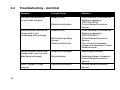
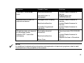
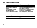
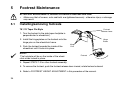
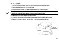
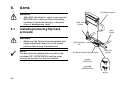
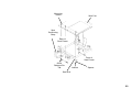
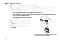
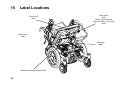
1
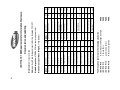
Invacare® XTERRA GT
Power Chair
User Manual
2
114.5kg
25deg
Overall Width
Folded Length
Folded Width
Folded Height
Total Mass (Weight)
Mass (Weight) of
the Heaviest Part
Static Stability Downhill
Static Stability Sideways
Energy Consumption (Range)
Dynamic Stability Uphill
Obstacle Climbing
Maximum Speed Forward
Minimum Braking Distance
from Maximum Speed
ISO 7176 Pt 5
ISO 7176 Pt 5
ISO 7176 Pt 5
ISO 7176 Pt 5
ISO 7176 Pt 5
C.E.N.
ISO 7176 Pt 1
ISO 7176 Pt 1
ISO 7176 Pt 4
ISO 7176 Pt 2
ISO 7176 Pt 10
ISO 7176 Pt 6
ISO 7176 Pt 3
2260mm
11.8km
80mm
3
22.8km
29deg
28deg
114.5kg
118.5kg
N/A
N/A
N/A
657mm
1065mm
Max.
Requirement
Seat Surface Height
at Front Edge
ISO 7176 Pt 7
ISO 7176 Pt 5
ISO 7176 Pt 5
Static, Impact and Fatigue Strength
Climatic Tests
power and Controls
Resistance to Ignition
ISO 7176 Pt 8
ISO 7176 Pt 9
ISO 7176 Pt 15
ISO 7176 Pt 16
PASS
PASS
PASS
PASS
Turn Around Width Between
Limiting Walls
Minimum Turning Radius
Horizontal Location of Axle
Handrim Diameter
ISO 7176 Pt 7
ISO 7176 Pt 7
Front Location of
Armrest Structure
(Front Armrest to Backrest)
Armrest to Seat Distance
ISO 7176 Pt 7
ISO 7176 Pt 7
Leg to Seat Surface Angle
Footrest to Seat Distance
ISO 7176 Pt 7
ISO 7176 Pt 7
Backrest Height
ISO 7176 Pt 7
Backrest Angle
Effective Seat Width
ISO 7176 Pt 7
ISO 7176 Pt 7
Effective Seat Depth
Seat Plane Angle
ISO 7176 Pt 7
ISO 7176 Pt 7
ISO Test
Method
The Wheelchair conforms to the following standards:
2260mm
11.8km
40mm
3
22.8km
27deg
118.5kg
N/A
N/A
N/A
657mm
1065mm
Overall Length with Legrest
ISO 7176 Pt 5
Min.
Requirement
ISO Test
Method
Maximum Occupant Mass (Weight): 114kg (250lbs)
Model Designation: XTERRA GT Mid wheel drive power chair
Address: South Road, Bridgend Industrial Estate, Bridgend. CF31 3PY
Manufacturer: Invacare Limited
Documentation and Labelling
1250mm
577mm
120mm
N/A
365mm
190mm
85deg
436mm
335mm
12deg
523mm
515mm
500mm
5deg
Min.
Max.
577mm
120mm
N/A
365mm
190mm
85deg
436mm
335mm
12deg
523mm
515mm
500mm
5deg
1250mm
ISO 7176-15: 1996 Requirements for Information Disclosure,
Warranty Terms & Conditions
Standard INVACARE terms
This is to certify that your XTERRA GT power chair is warranted by INVACARE Ltd., for a period of 1
year.
1. Only INVACARE chairs purchased at full price are warranted against defective workmanship and
materials.
2. If a defect or fault is discovered the INVACARE dealer from whom the appliance was obtained
should be notified immediately.
3. The manufacturer will not accept responsibility for damage caused by misuse or non-observance
of the instructions set out in the users manual.
4. During the period of the Warranty, any parts that have become defective due to faulty workmanship or materials, will be renewed or repaired without charge by the INVACARE dealer.
5. The Warranty will be forfeited should any unauthorised alteration be made to the equipment.
6. The Purchaser’s statutory rights under the Consumer Protection Act are not affected.
3
Limitation of liability
This Warranty does not extend to the consequential costs resulting from fault clearance, in particular
freight and travel costs, loss of earnings, expenses etc.
4
•
natural wear and tear
•
inappropriate or incorrect use
•
defective assembly or setting-up by the purchaser or third parties
•
defective or neglectful treatment
•
use of unsuitable spares
Contacting Invacare
For questions or support, please contact your authorised INVACARE Dealer. He has the necessary
know-how and equipment plus the special knowledge concerning your wheelchair which enables
him to offer you all-round satisfactory service.
Should you wish to contact us directly, we are at your service under the following addresses and
phone numbers.
United Kingdom
INVACARE Ltd.
South Road Bridgend Mid Glamorgan - CF31-3PY
Tel (Customer Service): 01656 - 647 327 Fax (Customer Service): 01656 - 649 016
France
INVACARE POIRIER S.A.
Les Roches F-37230 Fondettes
Tel (Service Après-Vente): 02 47 - 62 64 15 Fax (Service Après-Vente): 02 47 - 62 64 64
Deutschland
INVACARE Deutschland GmbH
Dehmer Str. 66 D-32549 Bad Oeynhausen
Tel (Kundendienst): 05731 - 754 210 Fax (Kundendienst): 05731 - 754 216
5
The Netherlands
INVACARE BV
Celsiusstraat 46
NL-6716 BZ Ede
Tel : +31 - (0) 318 - 550 056 Fax: +31 - (0) 318 - 555 054
Sverige
INVACARE AB
Fagerstagatan 9, S-163 91 Spånga.
Spain
INVACARE SA
c/Areny, s/n, Poligon Industrial de celrà, 17460 Celrà (girona) - España
Tel. 0972 - 49 32 00 Fax: 0972 - 49 32 20
Italy
Mecc San S.R.L.
Via Dei Pini, 35 I - 36016 Thiene (VI) - Italia
Tel: 0445 - 380059 Fax: 0445 - 380034
Portugal
INVACARE PORTUGAL Lda
Rua Senhora de Campanhâ, 105 4369-001 Porto - Portugal
Tel. 02 - 510 57 39 Fax: 02 - 510 50 20
6
Contents
ISO 7176-15: 1996 Requirements for Information Disclosure,
Documentation and Labelling ......................................................................... 2
Warranty Terms & Conditions .......................................................................... 3
Standard INVACARE terms ......................................................................................................... 3
Limitation of liability ..................................................................................................................... 4
1
Contacting Invacare ......................................................................................... 5
Introduction..................................................................................................... 10
1.1
1.2
2
Safety Notes .................................................................................................... 14
2.1
2.2
2.3
2.4
3
4
Important symbols in this manual .................................................................................... 12
Type classification and area of use .................................................................................. 13
Repair or service information ..........................................................................................
General safety notes .......................................................................................................
Safety information on electromagnetic interference .........................................................
Safety precautions/safe operation ...................................................................................
14
14
17
18
Some Useful Tips ............................................................................................ 21
Safety Inspection Checklist ........................................................................... 26
4.1
4.2
4.3
4.4
Troubleshooting - mechanical .........................................................................................
Troubleshooting - electrical ..............................................................................................
Checking battery charge level .........................................................................................
Care and maintenance ....................................................................................................
29
30
32
33
7
5
Footrest Maintenance .................................................................................... 34
5.1
5.2
5.3
5.4
5.5
5.6
5.7
5.8
5.9
5.10
5.11
6.
Arms ................................................................................................................ 50
6.1
6.2
7
Replacing seat positioning strap ...................................................................................... 54
Batteries .......................................................................................................... 56
8.1
8.2
8.3
8
Installing/removing flip back armrests ............................................................................. 50
Adjusting flip back armrests ............................................................................................ 52
Van Seat .......................................................................................................... 54
7.1
8
Installing/removing footrests ........................................................................................... 34
Footrest height adjustment .............................................................................................. 36
Adjusting/replacing telescopic front rigging support ........................................................ 38
Installing adjustable angle flip-up footplate hinge ............................................................. 39
Installing/adjusting adjustable angle flip-up footplates ..................................................... 40
Adjustable angle flip-up footplate angle adjustment ......................................................... 42
Adjustable angle flip-up footplate alignment and/or angle adjustment .............................. 43
Composite/articulating footplate heel loop replacement .................................................. 44
Installing/removing elevating legrests .............................................................................. 45
Raising/lowering elevating legrests and/or adjusting calfpads ......................................... 47
Removing/installing/adjusting the cage footrest ............................................................... 48
Removing/installing batteries ........................................................................................... 56
Connecting battery cables ............................................................................................... 63
Batteries and battery charging ........................................................................................ 71
10
Motor Locks/Forks ......................................................................................... 75
10.1 Disengaging/engaging motor lock levers ......................................................................... 75
10.2 Adjusting forks ................................................................................................................. 76
11
Controls and Operating your Power Chair ................................................... 77
11.1 Operation ........................................................................................................................ 77
12
Troubleshooting .............................................................................................. 80
12.1 Power chair will not drive, ON/OFF light does not come on, when ON/OFF switch is
pressed. .......................................................................................................................... 80
12.2 Power chair pulls to one side. .......................................................................................... 80
12.3 Power chair will not drive - ON/OFF light flashing. ........................................................... 81
13
14
15
Transportation ................................................................................................ 82
Technical Specifications ................................................................................ 84
Label Locations .............................................................................................. 86
9
1
Introduction
Dear User
First of all we wish to thank you for your confidence in our products! We hope you will enjoy your
new Powerchair.
This manual contains important hints and information on:
•
Safety
•
Operation
•
Care and maintenance
Please familiarise yourself thoroughly before making your first trip.
The information contained in this document is subject to change without notice.
As a manufacturer of wheelchairs, Invacare endeavours to supply a wide variety of wheelchairs to
meet many needs of the end user. However, final selection of the type of wheelchair to be used by
an individual rests solely with the user and his/her healthcare professional capable of making such a
selection.
Do not operate this equipment without first reading and understanding this manual. If you are unable
to understand the warnings, cautions, and instructions, contact your dealer otherwise injury or
damage may result.
10
NOTE:
Not all of the components within this manual will necessarily be available with your XTERRA GT
power wheelchair. This manual is a multinational operator’s manual and any references not applicable to your product should be ignored.
11
1.1
Important symbols in this manual
WARNING: THIS SYMBOL WARNS YOU OF DANGER!
•
Follow the instructions to avoid injury to the user or damage to the product!
NOTE:
This symbol indicates hints and suggestions which should help make operating the product easier
and point out special functions.
Requirements:
•
12
This symbol indicates a list of the different tools and other requirements you will need to do
certain maintenance work.
1.2
Type classification and area of use
The XTERRA GT is available with 2 maximum speed options.
•
The 4mph model is a Class 2 vehicle. The ACS Remote has 4 preset drive programs.
•
The 7.5mph model is a Class 3 vehicle and as such is equipped with lights and a rear view
mirror fitted as standard. In addition to the same 4 preset drive programs as the 4mph model
setting 5 gives the additional top speed.
WARNING:
•
Under no circumstances must the top speed of the Class 2 XTERRA GT be increased, to do so
will infringe Road Traffic Act Regulations.
The Class 3 XTERRA is of course fully compliant and may be used on roads with the exceptions of
motorways, unrestricted dual carrigeways, cycle lanes and bus lanes.
When used on footpath, pavements, bridleways and pedestrian areas speed must be restricted to
4mph (setting 5 must not be used in these areas).
Persons under the age of 14 years must not use a Class 3 vehicle.
13
2
Safety Notes
2.1
Repair or service information
Setup of the Electronic Control Unit is to be performed ONLY by individuals certified by Invacare.
The final tuning adjustments of the controller may affect other activities of the wheelchair. Damage to
the equipment could occur under these circumstances. If non-certified individuals perform any work
on these units, the warranty is void.
2.2
General safety notes
GENERAL WARNINGS
14
•
Performance adjustments should only be made by professionals of the healthcare field or
persons fully conversant with this process and the driver's capabilities. Incorrect settings could
cause injury to the driver, bystanders, damage to the chair and to surrounding property.
•
After the wheelchair has been setup, check to make sure that the wheelchair performs to the
specifications entered during the setup procedure. If the wheelchair does NOT perform to
specifications, turn the wheelchair OFF immediately and re-enter setup specifications. Repeat
this procedure until the wheelchair performs to specifications.
•
DO NOT climb, go up or down ramps or traverse slopes greater than 9°.
•
DO NOT attempt to move up or down an incline with a water, ice or oil film.
•
DO NOT attempt to drive over curbs or obstacles greater than 50mm (2in) in height. Doing so
may cause your wheelchair to turn over and cause bodily harm or damage to the chair.
•
Always stop before climbing an obstacle. Approach slowly until castors contact the obstacle.
Apply power and the action of the Sure-Step™ feature will lift the castors over the obstacle.
Weight is transferred to the drive wheels providing traction and motor strength to power the
chair over the obstacle.
•
DO NOT use parts, accessories, or adapters other than those authorised by Invacare.
•
DO NOT stand on the frame of the wheelchair.
TYRE PRESSURE
•
DO NOT use your wheelchair unless it has the proper tyre pressure (P.S.I.). DO NOT
overinflate the tyres. Failure to follow these suggestions may cause the tyre to explode and
cause bodily harm. The recommended tyre pressure is listed on the side wall of the tyre.
BATTERIES
•
The warranty and performance specifications contained in this manual are based on the use of
deep cycle gel cell batteries. Invacare strongly recommends their use as the power source for
this unit.
•
Carefully read battery/battery charger information prior to installing, servicing or operating your
wheelchair.
ELECTRICAL
•
Extreme care should be exercised when using oxygen in close proximity to electrical circuits.
Contact your oxygen supplier for instructions in the safe use of oxygen.
15
RAIN TEST
•
INVACARE has tested its power wheelchairs in accordance with ISO 7176 Part 9 “Rain Test”.
This provides the end user or his/her attendant sufficient time to remove his/her power wheelchair from a rain storm and retain wheelchair operation.
•
DO NOT leave power wheelchair in a rain storm of any kind.
•
DO NOT use power wheelchair in a shower or leave it in a damp bathroom while taking a
shower.
•
DO NOT leave power wheelchair in a damp area for any length of time.
•
Direct exposure to rain or dampness will cause the chair to malfunction electrically and mechanically and may cause the chair to rust prematurely.
•
Check to ensure that the battery covers are secured in place.
•
DO NOT use the joystick if the boot is torn or cracked. If the joystick boot becomes torn or
cracked, replace IMMEDIATELY.
WEIGHT TRAINING
•
Invacare DOES NOT recommend the use of its wheelchairs as a weight training apparatus.
Invacare wheelchairs have NOT been designed or tested as a seat for any kind of weight
training. If occupant uses said wheelchair as a weight training apparatus, Invacare shall NOT
be liable for bodily injury and the warranty is void.
WEIGHT LIMITATION
•
16
The XTERRA GT has a maximum user weight limitation of 114kg (18stone).
2.3
Safety information on electromagnetic interference
This electric vehicle was successfully tested in accordance with international standards as to its
compliance with Electromagnetic Interference (EMI) regulations. However, electromagnetic fields,
such as those generated by radio and television transmitters, and cellular phones, can influence the
functions of electric vehicles. Also, the electronics used in our vehicles can generate a low level of
electromagnetic interference, which however will remain within the tolerances permitted by law. For
these reasons we ask you to please observe the following precautions:
WARNING: DANGER OF MALFUNCTION DUE TO ELECTROMAGNETIC INTERFERENCE!
•
Do not switch on or operate portable transceivers or communication devices (such as radio
transceivers or cellular phones) when the vehicle is switched on!
•
Avoid getting near strong radio and television transmitters!
•
In case the vehicle should be set in motion unintentionally or the brakes are released, switch it
off immediately!
•
Adding electrical accessories and other components or modifying the vehicle in any way can
make it susceptible to electromagnetic interference. Keep in mind that there is no sure way to
determine the effect such modifications will have on the overall immunity of the electronic
system!
•
Report all occurrences of unintentional movement of the vehicle, or release of the electronic
brakes to the manufacturer!
17
2.4
Safety precautions/safe operation
IMPORTANT WARNING
•
The day-to-day activities and the more advanced power chair techniques depend, on your
physical capabilities and your own specific circumstances. Our recommendations may occasionally differ from those of your Therapeutic Adviser or Physician, as they have a better
understanding of your abilities. Where this is the case, you MUST FOLLOW THEIR advice, they
are better placed to tell you what is suitable for you and what is not.
•
DO NOT use your power chair when your driving ability is impaired by medication or alcohol.
CAUTION
18
•
Avoid using your power chair on rough ground or in adverse weather conditions (snow or ice),
always steer clear of obstacles where possible, ensure your clothing and hands are kept clear
of all moving parts, ask for assistance when descending or ascending steep gradients. Never
attempt to negotiate stairs. Never use an escalator to move a power chair between floors. Due
to both the weight of a power chair and its occupant it is not advisable to attempt to be assisted
up and down stairs whilst the power chair is occupied.
•
If you are a user with limited mobility we advise that in the case of adverse weather conditions
i.e. extreme cold, DO NOT attempt a journey without an accompanying attendant. In the event
of a power failure you could become stranded in an isolated area, where there is the strong
possibility you will be unable to get immediate assistance.
•
Braking of your power chair is dependent on electromagnetic motor brakes. When these are
disengaged by declutching the motor gear box drive system, the chair is in freewheel mode,
this mode is for emergency use only and motor gear boxes should remain engaged at all other
times.
•
To avoid the power chair freewheeling, special care must be taken to engage motor brakes.
SAFETY INDOORS
•
When using your power chair indoors always consider the following potential hazards:
•
Beware of the fact that many of the premises where you are likely to use your power chair may
not have been designed with this consideration in mind. You should therefore have an awareness for safety when encountering the likes of narrow doorways, steps, high surfaces, protruding wall fittings and every day household items such as children’s toys, electrical appliances
etc. Take extra care in kitchen environments.
•
Consider the fire evacuation procedures for buildings you may be entering. Never put yourself
at risk and ensure that you can be easily evacuated in the event of an emergency.
NOTE
power chairs drive very quietly, generally travel faster than the average walking pace and are low to
the ground. Always consider these factors when using your powered Wheelchair in busy pedestrian
areas.
COPING WITH EVERYDAY OBSTACLES
•
Coping with the irritation of everyday obstacles can be alleviated somewhat by learning how to
manage your wheelchair. Keep in mind your centre of gravity to maintain stability and balance.
•
DO NOT attempt to lift the wheelchair by any removable (detachable) parts. Lifting by means of
any removable (detachable) parts of a wheelchair may result in injury to the user or damage to
the wheelchair.
•
Also, be aware of detachable parts such as armrests or legrests. These must NEVER be used
for hand-hold or lifting supports, as they may be inadvertently released, resulting in possible
injury to the user and/or assistant(s).
•
When learning a new assistance technique, have an experienced assistant help you before
attempting it alone.
19
SAFETY/HANDLING OF WHEELCHAIRS
20
•
Use this information only as a “basic” guide. The techniques that are discussed on the following
pages have been used successfully by many.
•
Individual wheelchair users often develop skills to deal with daily living activities that may differ
from those described in this manual. Invacare recognises and encourages each individual to try
what works best for him/her in overcoming environmental obstacles that they may encounter,
however ALL WARNINGS and CAUTIONS given in this manual MUST be followed. Techniques
in this manual are a starting point for all new wheelchair user and assistant with “safety” as the
most important consideration for all.
3
Some Useful Tips
Before you venture off on your first journey, ensure that everything is adjusted to your specific
needs, read this manual to familiarise yourself with the product and its functions. DO NOT attempt
to drive without attendant on hand until you are fully proficient in using and manoeuvring your power
chair.
Ensure power is switched off before entering or leaving your power chair. Before
switching on, check that both motors are engaged, tyres are inflated to the
correct pressure and are in good condition. When on the move DO NOT attempt
turns at full speed, especially while travelling downhill. Before changing from
forward to reverse, and vice versa, you must stop, failure to do so will cause
severe damage to the electronics. DO NOT use your power chair beyond its
limitations. Due to both the weight of a powered Wheelchair and its occupant it is
not advisable to attempt to be assisted up and down stairs whilst seated.
When entering or leaving your power chair, DO NOT stand on the footplates.
If you have to brake in an emergency, release the joystick. DO NOT switch off
power while the power chair is moving, it would cause an abrupt, sharp stop.
DO NOT use your power chair beyond the limitations set out in this manual
concerning kerb height, gradients, etc.
Stability and Balance
To ensure stability and safe control of your power chair you must at all times
maintain proper balance. The power chair is designed to remain stable and
21
upright during normal use, so long as you do not move your centre of gravity outside the normal
seating position.
REACHING - BENDING FORWARD
•
Ensure power is OFF. DO NOT lean your body forward out of the power chair
further than the length of the armrests.
•
DO NOT attempt to pick up objects from the floor by bending forward and
reaching between your knees.
•
DO NOT attempt to reach objects by sliding forward to the edge of the power
chair seat.
REACHING - BENDING BACKWARDS
22
•
Again ensure power is switched OFF.
•
DO NOT reach back any further than your arm will extend without changing
your sitting position.
•
DO NOT lean over the top of the backrest as it will shift the centre of gravity,
risking tipping over.
•
DO NOT hang heavy loads or objects on the backrest. They may make the power chair unstable, especially on an incline.
TRANSFERRING TO AND FROM OTHER SEATS
•
ALWAYS turn the wheelchair power OFF and engage the motor locks/clutches to prevent the
wheels from moving BEFORE attempting to transfer in or out of the wheelchair. Also, make
sure every precaution is taken to reduce the gap distance by turning both rear castors away
from the object you are transferring onto.
•
When transferring, position yourself as far back as possible in the seat. This will prevent broken
screws, damaged upholstery and the possibility of the
wheelchair tipping forward.
•
Note: This activity may be performed independently provided
you have adequate mobility and upper body strength.
•
Position the wheelchair as close as possible along side the
seat to which you are transferring, with the rear castors
pointing away from it.
•
Engage motor locks/clutches.
•
Shift body weight into seat with transfer.
•
During independent transfer, little or no seat platform will be
beneath you. Use transfer board if at all possible.
23
NEGOTIATING GRADIENTS/SLOPES
•
Never attempt to climb or descend an incline where the surface is
rough, wet or slippery (gravel, loose chippings, grass, rain, black
ice, snow etc.).
•
If you are in a situation where by the power chair fails to climb a
ramp and stalls midway through the manoeuvre, DO NOT attempt
to turn the power chair to drive back down in a forward facing
direction, always reverse slowly in a steady, flowing action and DO
NOT brake harshly, as this will upset balance in this situation. If
possible, always seek the assistance of an attendant.
NEGOTIATING KERBS
•
When approaching kerbs wherever possible
mount and dismount pavements via ramps.
Always approach the kerb head on, not at an
angle.
3
2
Direction of Travel
24
YOU, YOUR POWER CHAIR AND OTHERS
•
power chairs are strictly forbidden on motorways and their use is strongly discouraged on
highways with fast moving traffic.
•
On the Pavement, in Pedestrian Zones or in Supermarkets it is obvious that you must show as
much consideration and common sense to others as you expect from them.
•
When you cross the carriageway of a public road take extra care and allow time to cross,
observe the Highway code. Although you are not required by law to hold a driving license, you
are responsible and fully liable for proper operation. An important fact to bear in mind is that
you must not present a traffic hazard even in the event of a breakdown. The most common
cause may be discharged batteries. It is important to keep the batteries in a fully charged
condition, we can only repeat this warning at this stage. If you do suffer a breakdown for
whatever reason, you should immediately: seek the assistance of a passer-by. Explain where to
find the motor disengagement/declutching lever, ask him/her to switch to freewheel, so that the
power chair can be pushed by hand and moved. When in a safe place always ensure motor
gear boxes are re-engaged.
SAFEGUARDING OTHERS
•
If there are children in your family or household, keep the power chair away from them. It is not
intended to be used as a toy. It isn’t just about safeguarding the power chair, it is also about
protecting others and yourself from injury.
•
Finally, we want you to get the most out of your INVACARE power chair, ensuring that the
safety of yourself and others is never in jeopardy. If you are in any doubt about safe techniques,
handling or care of the power chair, contact a recognised expert before putting yourself and
others at risk.
25
4
Safety Inspection Checklist
Initial adjustments should be made to suit personal body structure/user capability and preference.
Thereafter follow these maintenance procedures:
Item
Initially
General
Wheelchair rolls straight
(no excessive drag or pull to one side).
X
Motor brushes & motor gearbox coupling
Clothing guards
Ensure all fasteners are secure.
Arms
Secure but easy to release;
adjustment levers engage properly.
Adjustable height arms operate
and lock securely.
Armrests
Inspect for rips in upholstery.
Arm rest pad sits flush against arm tube.
26
inspect/
adjust
weekly
inspect/
adjust
monthly
inspect/
adjust
periodically
X
X
X
X
X
X
X
X
X
X
X
X
Item
Initially
Seat and back upholstery
Inspect for rips or sagging.
Drive wheels
Axle nut and wheel mounting nuts are secure.
No excessive side movement or binding when
lifted and spun when disengaged
(free-wheeling).
Castors
Inspect wheel/fork assembly for proper tension
by spinning castor; castor should come to a
gradual stop.
Loosen/tighten locknut if wheel wobbles
noticeably or binds to a stop.
CAUTION: As with any vehicle, the wheels and
tyres should be checked periodically
for cracks and wear, and should be replaced.
Castor/wheel/fork/head tube
Ensure all fasteners are secure.
inspect/
adjust
weekly
inspect/
adjust
monthly
X
inspect/
adjust
periodically
X
X
X
X
X
X
X
X
X
X
X
27
Item
Tyres
Inspect for flat spots and wear.
If pneumatic tyres check for proper inflation.
CAUTION: As with any vehicle, the wheels
and tyres should be checked periodically for
cracks and wear, and should be replaced.
CLEANING
Clean upholstery and armrests.
Initially
inspect/
adjust
weekly
X
X
X
X
X
inspect/
adjust
monthly
inspect/
adjust
periodically
X
NOTE:
Every six (6) months take your wheelchair to a qualified dealer for a thorough inspection and
servicing. Regular cleaning will reveal loose or worn parts and enhance the smooth operation of
your wheelchair. To operate properly and safely, your wheelchair must be cared for just like any
other vehicle. Routine maintenance will extend the life and efficiency of your wheelchair.
28
4.1
Troubleshooting - mechanical
Chair Veers Sluggish Turn/
Left/Right
Performance
Castors
flutter
X
X
X
X
X
X
X
Looseness In Chair
Squeaks
and Rattles
X
X
Chair 3 Wheels
X
Solutions
If pneumatic, check tyres for correct
and equal pressure.
Check for loose stem nuts/bolts.
Check that both castors contact
ground at the same time.
Solutions
If pneumatic, check tyres for correct and
equal pressure.
X
Check for loose stem nuts/bolts.
29
4.2
Troubleshooting - electrical
Symptom
Probable Cause
Solutions
Batteries draw excessive
current when charging.
Battery failure.
Check batteries for shorted cell.
Replace if necessary
(PROCEDURE 8).
Contact Dealer/Invacare for
Service.
Electrical malfunction.
Battery indicator flashes the
charge level is low immediately after recharge.
Battery failure.
Malfunctioning battery
charger.
Electrical malfunction.
30
Check batteries for shorted cell.
Replace if necessary
(PROCEDURE 8).
Contact Dealer/Invacare for
Service.
Poor connections between
charger and wheelchair. Contact
Dealer/Invacare.
Battery indicator flashes the
charge level is low, too soon
after being recharged.
Batteries not charged.
Have charger checked.
Weak batteries.
Replace batteries if necessary.
Contact Dealer/Invacare for
Service.
Motor “chatters” or runs
irregular.
Electrical malfunction.
Contact Dealer/Invacare for
Service.
Symptom
Probable Cause
Solutions
Only one (1) drive wheel
turns.
Electrical malfunction.
Contact Dealer/Invacare for
Service.
Engage motor lock
(PROCEDURE 9).
One motor lock is
disengaged.
Joystick erratic or does not
respond as desired.
Damaged motor coupling.
Electrical malfunction.
Controller Programmed
improperly.
Wheelchair does not respond
to commands. power
indicator OFF - even after
recharging.
Poor battery terminal
connection.
Electrical malfunction.
Blown Fuse
Contact Dealer/Invacare for
Service.
Contact Dealer/Invacare for
Service.
Contact Dealer/Invacare for
Service.
Clean terminals (PROCEDURE
8).
Contact Dealer/Invacare for
Service.
Replace the fuse in Procedure
10.
NOTE:
For additional troubleshooting information and explanation of electrical symptoms, refer to additional sections in this procedure of the manual.
31
4.3
Checking battery charge level
The following “Do’s” and “Don’ts” are provided for your convenience and safety.
32
Don’ts
Do’s
Don’t perform any installation or
maintenance without first reading this
manual.
Read and understand this manual and any service
information that accompanies a battery and charger
before operating the wheelchair.
Don’t make it a habit to discharge
batteries to the lowest level.
Recharge as frequently as possible to maintain a
high charge level and extend battery life.
Don’t use randomly chosen batteries or
chargers.
Follow recommendations in this manual when
selecting a battery or charger.
Don’t put new batteries into service before
charging.
Fully charge a new battery before using.
Don’t tap on clamps and terminals with
tools.
Push battery clamps on the terminals. Spread
clamps wider if necessary.
Don’t mismatch your battery and
chargers.
Use ONLY a GEL charger for a GEL or sealed
battery.
4.4
Care and maintenance
NOTE:
Have your vehicle checked once a year by an authorised Invacare dealer in order to maintain its
driving safety and roadworthiness.
Cleaning the vehicle
When cleaning the vehicle, pay attention to the following points:
•
Only use a damp cloth and gentle detergent.
•
Do not use any scrubbing agents.
•
Do not subject the electronic components to any direct contact with water.
•
Do not use high-pressure cleaning devices.
33
5
Footrest Maintenance
AFTER ANY ADJUSTMENTS, REPAIR OR SERVICE AND BEFORE USE:
•
5.1
Make sure that all screws, nuts and bolts are tightened securely - otherwise injury or damage
may result.
Installing/eemoving footrests
70°/ 70° Taper Pin Style
Footrest
Release Lever
1. Turn the footrest to the side (open footplate is
perpendicular to wheelchair).
Hinge
Plates
2. Install the hinge plates on the footrest onto the
hinge pins on the wheelchair frame.
3. Push the footrest towards the inside of the
wheelchair until it locks into place.
NOTE:
The footplate will be on the inside of the wheelchair when locked in place.
Hinge
Pins
Footrest
4. Repeat STEPS 1-3 for other footrest assembly.
5. To remove the footrest, push the footrest release lever inward, rotate footrest outward.
6. Refer to FOOTREST HEIGHT ADJUSTMENT in this procedure of the manual.
34
60°, 70°, 70° Taper
1. Turn the footrest to the side (open footplate is perpendicular to wheelchair itself).
2. Insert footrest mounting pin into mounting tube.
3. Push the footrest towards the inside of the wheelchair until it locks into place.
NOTE:
The footplate will be on the inside of the wheelchair when locked in place.
4. Repeat STEPS 1- 3 for the other footrest assembly.
5. To remove the footrest, push the footrest release lever inward, rotate footrest outward.
6. Refer to FOOTREST HEIGHT ADJUSTMENT in this procedure of the manual.
Footrest
Mounting Pin
Mounting Tube
Footrest
Release Lever
Footplate
35
5.2
Footrest height adjustment
60°, 70°, PW93
1. Remove any accessory from the footrest(s).
Upper Footrest Support
2. Remove the footrest from the wheelchair. Refer to INSTALLING/REMOVING FOOTRESTS in this procedure of
the manual.
NOTE:
Lay the footrest on a flat surface to simplify this procedure.
3. Remove the mounting screw, washers and locknut that
secure the lower footrest to the footrest support.
Mounting Screw
Locknut
Washer
Lower
Footrest
Assembly
4. Reposition the lower footrest to the desired height.
90o Footrest
5. Reinstall the mounting, washers and locknut that
secure the lower footrest to the footrest support and
tighten securely.
Washer
6. Repeat STEPS 1-5 for the opposite side of the wheelchair footrest, if necessary.
7. Reinstall the footrest(s) onto the wheelchair. Refer to
INSTALLING/REMOVING FOOTRESTS in this procedure of the manual.
8. Reinstall any accessory onto the footrest(s).
36
Locknut
Mounting
Tube
Mounting
Screw
70° Taper
1. Remove any accessory from the footrest(s).
2. Remove the footrest from the wheelchair. Refer to INSTALLING/REMOVING FOOTRESTS in this
procedure of the manual.
NOTE:
Lay the assembly on a flat surface to simplify this procedure.
Note the position of spacers before disassembly.
3. Remove the mounting screw and coved spacer that secures the lower footrest assembly.
4. Position the footrest assembly to the desired height.
5. Secure lower footrest assembly with existing mounting screw and coved spacer. Securely tighten.
NOTE:
Make sure spacers are positioned properly when reassembling so not to damage frame mounting
tubes.
6. Reinstall the footrest(s) onto the wheelchair. Refer to INSTALLING/
REMOVING FOOTRESTS in this procedure of the manual.
7. Reinstall any accessory onto the footrest(s).
37
5.3
Adjusting/replacing telescopic front rigging support
1. Remove the two (2) mounting screws, spacers and locknuts that secure the telescopic front
rigging support to the seat frame.
2. Perform one (1) of the following:
•
Slide existing telescopic front rigging support to one (1) of three (3) depth positions.
•
Remove existing telescopic front rigging support and install NEW telescopic front rigging
support.
3. Secure telescopic front rigging at desired depth with existing two (2) mounting screws, spacers,
and locknuts. Securely tighten.
NOTE:
The two (2) telescopic front rigging supports can be positioned at different depths depending on
the need of the user.
Seat
Frame
Mounting
Screws
Spacers
Locknut
38
Telescopic
Front Tube
5.4
Installing adjustable angle flip-up footplate hinge
1. Position adjustable angle flip-up footplate (footplate) hinge on the footrest support tube at the
desired height.
2. Position mounting screw, washers, spacer, and locknut on the footrest support as shown.
3. Flip the footplate hinge to the UP position.
NOTE:
The footplate hinge will fall to the DOWN position.
4. Tighten the mounting screw, washer, and locknut that secure the footplate hinge to the footrest
support until the footplate hinge remains in the UP position.
5. Check the up and down motion of the footplate hinge to make sure the user of the wheelchair
can operate the footplates easily.
NOTE:
If footplate's motion is too tight, loosen the mounting screw and locknut approximately 1/4-turn
counter clockwise.
If the footplate's motion is too loose, tighten
mounting screw and locknut approximately 1/4turn clockwise.
6. Adjust footplate. Refer to INSTALLING/ADJUSTING ADJUSTABLE ANGLE FLIP-UP FOOTPLATES in this procedure of the manual.
Mounting Screw
Footplate
Hinge
Washers
Locknut
Footrest Support
Spacer
39
5.5
Installing/adjusting adjustable angle flip-up footplates
Installing
1. Slide the half clamp over the footplate hinge.
o
90 Footrest Support
2. Loosely tighten the two (2) flat screws that
secure the footplate to the half clamp.
3. Adjust the footplates to the necessary angle
and depth for the user. Refer to ADJUSTING
ADJUSTABLE FLIP-UP FOOTPLATES in this
procedure of the manual.
Flat Screws
Articulating
Footplate
Footplate Hinge
Nylon
Adjustment
Screw
Half
Clamp
Footplate Hinge
Washers
Half Clamp
Locknuts
40
Adjusting
1. Remove the two (2) flat screws, washers and locknuts that secure articulating footplate to the
half clamp.
90o Footrest Support
NOTE:
Observe the angle of the articulating footplate
for reinstallation.
2. Move articulating footplate to one (1) of four
(4) mounting positions.
Flat Screws
Articulating
Footplate
Footplate Hinge
Nylon
Adjustment
Screw
NOTE:
If desired depth is still not obtained, rotate the
half clamp on the footplate hinge 180°.
3. Retighten the two (2) flat screws, washers
and locknuts.
NOTE:
The settings for positioning the articulating
footplates on the half-clamps may vary for each
footplate.
Half
Clamp
4. Refer to Adjustable Angle Flip-up Footplate
Angle Adjustment or Adjustable Angle Flip-up
Footplate Alignment and/or Angle Adjustment
in this procedure of the manual.
Washers
Footplate Hinge
Half Clamp
Locknuts
41
5.6
Adjustable angle flip-up footplate angle adjustment
1. Loosen, but do not remove the two (2) flat screws, washer and locknuts that secure the footplate
to the footplate hinge.
90o Footrest Support
2. Position the articulating footplate to the
necessary angle to accommodate the user.
3. Retighten the two (2) flat screws, washers
and locknuts.
Flat Screws
Articulating
Footplate
Footplate Hinge
Nylon
Adjustment
Screw
Footrest Support
Articulating Footplate
Half
Clamp
Footplate Hinge
Washers
Half Clamp
Locknuts
42
5.7
Adjustable angle flip-up footplate alignment and/or angle
adjustment
90o Footrest Support
NOTE:
It is not necessary to remove the footplate to
perform this adjustment.
1. Insert a flathead screwdriver through the half
clamp on the articulating footplate.
Flat Screws
Articulating
Footplate
Footplate Hinge
Nylon
Adjustment
Screw
2. Slowly turn nylon adjustment screw in or out
until articulating footplate is aligned to the
footrest assembly or the desired angle is
obtained.
Half
Clamp
Footrest Support
Footplate Hinge
Footplate
Washers
Half Clamp
Locknuts
43
5.8
Composite/articulating footplate heel loop replacement
Disassembly
Composite
Mounting
Screw
1. Remove the mounting screw and coved washer that
secures the lower half of the footrest to the
swingaway footrest assembly.
Mounting
Screw
Spacer
Composite
Footplate
2. Remove the lower footrest assembly.
3. Remove the mounting screw and locknut that
secure the heel loop to the footrest.
Locknut
4. Slide heel strap over cane of footrest assembly.
Articulating
1. Remove the two (2) mounting screws that secure the heel
loop to the articulating footplate.
Reassembly
1. Replace heel strap/loop.
Mounting Screw
Heel Loop
Articulating Footplate
2. Reverse preceding steps to reassemble.
NOTE:
When securing heel loop to the footrest, tighten mounting screw until the spacer is secure.
44
5.9
Installing/removing elevating legrests
Installing
Calfpad
1. Turn legrest to side (open footplate is perpendicular to wheelchair) and position mounting
holes in the legrest hinge plates with hinge pins
on the wheelchair frame.
2. Install the legrest hinge plates onto the hinge
pins on the wheelchair frame.
3. Rotate legrest toward the inside of the wheelchair until it locks in place.
Hinge Pins
Hinge Plates
Legrest
NOTE:
The footplate will be on the inside of the wheelchair when locked in place.
4. Repeat STEPS 1-3 for the opposite legrest.
Legrest Release Handle
5. After seated in wheelchair, adjust footplate to
correct height by loosening nut and sliding the
lower footrest assembly up or down until
desired height is achieved.
Bolt/Nut
45
Removing
1. Push the legrest release handle toward the inside of the wheelchair (facing the front of the
wheelchair) and swing the legrest to the outside of the wheelchair.
2. Lift up on the legrest and remove from the wheelchair.
3. Repeat STEPS 1-2 for opposite side of wheelchair.
46
5.10
Raising/lowering elevating legrests and/or adjusting calfpads
Raising/Lowering Elevating Legrests
1. Perform one (1) of the following:
•
RAISING -
Pull back on the release lever until the leg is at the desired height.
•
LOWERING hand.
Support leg with one (1) hand and push release lever downward with other
Adjusting Calfpads
Legrest to Normal Position
1. Turn the calfpad towards the outside of the
wheelchair.
2. Slide the calfpad up or down until the
desired position is obtained.
NOTE:
If one (1) of the top two (2) calfpad adjustment positions is being used, the legrest will
need to be raised to avoid interference with
the front stabilizers while going over obstacles
or going up and down ramps. Refer to RAISING/LOWERING ELEVATING LEGRESTS in
this procedure of the manual.
3. Turn the calfpad towards the inside of the
wheelchair.
Adjust Calfpad
Secure Calfpad
47
5.11
Removing/installing/adjusting the cage footrest
Removing/installing/depth adjustment
1. Remove the cushion.
2. Remove the four (4) mounting screws, spacers, and locknuts that secure the cage footrest to the
seat frame.
3. Perform one (1) of the following:
•
To remove cage footrest, pull footrest out of the seat assembly.
•
To adjust depth, adjust mounting tubes to desired depth and reinstall mounting screws.
Securely tighten.
4. To install, slide footrest into seat assembly to desired depth and reinstall mounting screws.
Securely tighten.
5. Reinstall cushion.
Height adjustment
1. Remove the two (2) mounting screws, tube clamps, and locknuts that secure the anti-rattle, slide
tube and footrest to upright tubes.
2. Adjust the footrest to desired position.
3. Reinstall the two (2) mounting screws, tube clamps, and locknut that secure the anti-rattle, slide
tube and footrest to upright tubes. Securely tighten.
48
Mounting Screws
Spacers
Locknut
Tube Clamp
Locknuts
Mounting
Screw
Upright
Tube
Anti-Rattle
Slide Tube
Footrest
49
6.
Arms
Flip Back Armrest
WARNING
•
6.1
After ANY adjustments, repair or service and
BEFORE use, make sure that all attaching
hardware is tightened securely - otherwise
injury or damage may result.
Rear Arm
Socket
Installing/removing flip back
armrests
Seat
Frame
WARNING
•
Make sure the flip back armrest release and
height adjustment levers are in the locked
position before using the wheelchair.
NOTE:
Flip back armrest release lever must be in the
unlocked (UP- HORIZONTAL) position when
placing the armrest into the arm sockets.
Quick Release
Pin
Flip Back Armrest Release Lever
Locked
(VERTICAL)
Unlocked
(HORIZONTAL)
50
Front Arm
Socket
Installing
1. Visually inspect to ensure flip back armrest release lever is in the unlocked HORIZONTAL
position.
2. Slide the flip back armrest into the arm sockets on the seat frame.
3. Install the quick release pin through the rear arm socket and flip back armrest.
4. Lock the flip back armrest by pressing the flip back armrest release lever into the VERTICAL
position.
5. Repeat STEPS 1-4 for the opposite flip back armrest.
Removing
1. Unlock the flip back armrest by positioning the flip back armrest release lever into the HORIZONTAL position.
2. Remove the quick release pin that secures the flip back armrest to the rear arm socket.
3. Pull up on the flip back armrest and remove the armrest from the arm sockets.
4. Repeat STEPS 1-3 for the opposite flip back armrest, if necessary.
51
6.2
Adjusting flip back armrests
WARNING
•
Make sure the flip back armrest release and
height adjustment levers are in the locked
position before using the wheelchair.
Positioning Flip Back Armrests for User Transfer
1. Unlock the flip back armrest by pulling the armrest release lever into the HORIZONTAL position.
WARNING
•
Armrest release lever must remain in the
horizontal position during transfer, otherwise
injury may result.
2. Pull up on the flip back armrest and remove the
armrest from the front arm socket.
3. Continue to pull up on the flip back armrest until
the armrest is out of the way.
4. Repeat STEPS 1-3 for opposite flip back armrest,
if necessary.
52
Flip Back
Armrest
Height
Adjustment
Lever
Front Arm
Socket
Locked
(VERTICAL)
Unlocked
(HORIZONTAL)
Armrest Release Lever
Locked
(VERTICAL)
Unlocked
(HORIZONTAL)
Positioning Flip Back Armrests for Use
1. Make sure the flip back armrest release lever is in the HORIZONTAL position.
2. Install the flip back armrest into the front arm socket.
3. Lock flip back armrest by pressing flip back armrest release lever into the VERTICAL position.
4. Lift up on flip back armrest to make sure the armrest is locked in place.
5. Repeat STEPS 1-4 for opposite flip back armrest, if necessary.
Adjusting
1. Unlock top of flip back armrest by pulling height adjustment lever into the HORIZONTAL position.
2. Adjust top of the flip back armrest to the desired height.
3. Lock top of flip back armrest by pushing height adjustment lever into the VERTICAL position.
53
7
Van Seat
WARNING
•
7.1
After ANY adjustments, repair or service and BEFORE use, make sure that all attaching
hardware is tightened securely - otherwise injury or damage may result.
Replacing seat positioning strap
Standard/Adjustable Seat frames
1. Remove the seat cushion from the seat pan.
2. Move the flip back armrests out of the way. Refer to USING/ADJUSTING FLIP BACK ARMRESTS in PROCEDURE 5 of this manual.
3. Remove the two (2) mounting screws, quick release pin tabs, spacers, and locknuts that secure
the seat pan and seat positioning straps to the seat frame.
4. Remove the two (2) halves of the seat positioning strap from the rear seat frame.
NOTE:
Quick release pin tabs are positioned underneath the seat positioning strap.
5. Reposition the two (2) new seat positioning strap halves underneath seat rails.
6. Reinstall the two (2) mounting screws, quick release pin tabs, spacers, and locknuts that secure
the seat pan and seat positioning straps to the seat frame and torque to 75-inch pounds.
7. Reinstall the seat cushion onto the seat pan.
54
Mounting
Screw
Seat Pan
Seat
Positioning
Strap
Rear of
Seat Frame
Front of
Seat Frame
Quick
Release Pin
Tab
Locknut
Spacer
Seat Rail
55
8
Batteries
WARNING
8.1
•
Make sure power to the wheelchair is OFF before performing this procedure.
•
The use of rubber gloves and chemical goggles is recommended when working with batteries.
•
Invacare strongly recommends that battery installation and battery replacement always be
done by a qualified technician.
•
After ANY adjustments, repair or service and BEFORE use, make sure all attaching hardware
is tightened securely - otherwise injury or damage may result.
•
This procedure MUST be performed while the wheelchair is unoccupied.
Removing/installing batteries
WARNING
56
•
Each battery weighs 16kg. Use proper lifting techniques (lift with your legs) to avoid injury.
•
Failure to use the correct battery size and/or voltage may cause damage to your wheelchair
and give you unsatisfactory performance.
•
Always use a battery lifting strap when lifting a battery. It also helps to prolong the life of the
battery.
Removing
1. Place the wheelchair in a well ventilated area where work can be performed without risking
damage to carpeting or floor covering.
2. Ensure the Joystick is switched off.
3. Pull release lever located underneath the front of the seat to disengage.
4. Tilt seat backward and lock seat in upward position with seat prop.
5. Disconnect the battery wiring
harness from the front battery.
Release Lever
6. Disconnect battery wiring
harness from the rear battery.
7. Disconnect the battery retention strap.
Seat Prop
Battery Retention
Battery
8. Lift the front battery out of the
base frame.
9. Slide rear battery forward and
lift out of base frame.
57
Installing
1. Install the rear battery into the base frame in the orientation shown before .
2. Slide the rear battery rearward.
3. Install the front battery into the base frame in the orientation shown .
4. Connect the battery retention strap.
5. Connect the battery wiring harness to the rear battery.
6. Connect the battery wiring harness to the front battery.
WARNING
•
When lowering the seat, ensure that hands and fingers are clear from underneath seat before
lowering, otherwise, injury may result.
•
After lowering seat, ensure that seat is locked securely in place before operating chair, otherwise serious personal injury, damage to the wheelchair and/or damage to surrounding property
may occur.
7. To lower seat: Lift up on seat with one hand. While holding seat, pull prop toward the front of the
seat. Lower seat.
58
Front Battery
Rear Battery
59
Direct mount method
Disconnecting Battery Cables (figure 3)
WARNING
•
•
NEVER allow any of your tools and/or battery cable(s) to
contact BOTH battery terminal(s)/ post(s) at the same
time. An electrical short may occur and serious personal
injury or damage may occur.
NEGATIVE
(-) Battery
RED
Terminal/ Battery
Post
Terminal
Cap
POSITIVE
(+) Battery
Terminal/
Post
TieWrap
The use of rubber gloves and chemical goggles is recommended when working with batteries.
NOTE:
Perform this procedure on one (1) battery and battery box at a
time. Repeat procedure for other battery box.
TieWrap
50Ah Battery
BLACK Battery
Terminal Cap
1. Disconnect the strap that secures the lid to the battery.
POSITIVE (+)
Red
Battery Cable
2 Lift up on battery box lid to expose underlying cables.
3. Cut the tie wraps that secure the battery covers to the terminals.
4. Perform one (1) of the following:
•
Direct Mount Method - Peel back battery covers to expose
ring terminal on each battery cable as follows:
RED battery cover from red battery cable.
BLACK battery cover from Black battery cable.
60
1/4-20
Hex
Flange
Locknut
1/4-20
Hex
Flange
Screw
Group 50Ah
Battery
NEGATIVE (-)
Black Battery
Cable
•
Battery Clamp Method - Peel back battery covers to
expose battery clamp on each battery cable as follows:
RED battery clamp cover from red battery cable.
BLACK battery clamp cover from Black battery cable.
3. Perform one (1) of the following:
•
Battery clamp method
RED Battery
Clamp Cover POSITIVE (+) Battery
Terminal/Post
NEGATIVE (-)
Battery
Terminal/Post
Tie-Wrap
Direct Mount Method
Remove the hex screw and locknut that secures the
NEGATIVE (-) black battery cable to the negative
battery terminal/post.
Remove the hex screw and locknut that secures the
POSITIVE (+) red battery cable to the positive battery
terminal/post.
BLACK Battery
Positive (+) RED
Battery Cable
Battery
Clamp
Hex Screw
•
Battery Clamp Method
Remove the hex screw that secures the NEGATIVE (-)
black battery cable to the battery clamp of the positive
battery terminal/post.
Remove the hex screw that secures the POSITIVE (+)
red battery cable to the battery clamp of the positive
battery terminal/post.
Mounting Plate
Negative (-)
BLACK
Battery Cable
POSITIVE (+)
Battery
Terminal/Post
50Ah
61
Tie-Wrap
NOTE:
To transfer battery clamps to new battery, perform the following:
Remove the hex screw and locknut that secures the battery clamp to the negative battery
terminal/post. Remove battery clamp.
Remove the hex screw and locknut that secures the battery clamp to the positive battery
terminal/post. Remove battery clamp.
62
8.2
Connecting battery cables
WARNING
•
NEVER allow any of your tools and/or battery cable(s) to contact BOTH battery terminal(s)/
post(s) at the same time. An electrical short may occur and serious personal injury or damage
may occur.
•
The use of rubber gloves and chemical goggles is recommended when working with batteries.
Perform one (1) of the following methods for connecting the battery cable(s):
•
For group 22 NF Batteries that have mounting holes in the battery terminal(s)/post(s) - Use
direct mount method.
•
For group 22 NF Batteries that do not have mounting holes in the battery terminal(s)/post(s) Use battery clamp method.
Direct Mount method (FIGURES 4 and 5)
1. Install battery terminal cap(s) onto battery cable(s) as follows:
•
RED battery terminal cap onto red battery cable.
•
BLACK battery terminal cap onto Black battery cable.
CAUTION
•
When connecting the battery cables to the battery(ies), the battery cable(s) MUST be connected to the battery terminal(s)/post(s) depending on battery type, otherwise damage to the
battery cable may result when installing battery terminal caps.
63
2. Connect battery cable(s) to battery(ies) terminal(s)/post(s) as follows (depending on battery
type):
•
Negative (-) BLACK battery cable to NEGATIVE (-) battery terminal/post.
•
Positive (+) RED battery cable to POSITIVE (+) battery terminal/post.
3. Secure the battery cable(s)/ring terminal(s) to the battery terminal(s)/post(s), BLACK to NEGATIVE (-) and RED to POSITIVE (+), with the provided 1/4-20 x 7/8-inch hex flange screw and hex
flange locknut. Securely tighten. (depending on battery type).
4. Verify all battery cable(s)/ring terminal(s) are correctly installed and securely tightened.
5. Slide terminal cap(s) down battery cable(s) and onto battery clamps.
6. Secure each terminal cap in place with a tie-wrap (Use tie-wraps 11-1/2-inches long).
NOTE:
It will be necessary to trim excess tie-wrap in order to install the battery box top(s).
7. Install the battery with lid into the wheelchair. Refer to INSTALLING/REMOVING BATTERIES in
this procedure.
NOTE:
New Battery(ies) MUST be fully charged BEFORE using, otherwise the life of the battery(ies) will
be reduced.
8. If necessary, charge the battery(ies). Refer to CHARGING BATTERIES in this procedure.
64
POSITIVE (+) Red
Battery Cable
POSITIVE (+)
Battery Terminal/Post
1/4-20 x 7/8-Inch
Hex Flange Screw
NEGATIVE (-)
Battery
Terminal/
Post
RED
Battery
Terminal
Cap
POSITIVE (+) Battery
Terminal/Post
TieWrap
1/4-20 Hex
Flange
Locknut
Group 50Ah
Battery
TieWrap
NEGATIVE (-) Battery
Terminal/Post
50Ah Battery
NEGATIVE (-) Black
Battery
Cable
Connect battery cable to
battery terminal as shown.
BLACK BatteryTerminal Cap
INSTALLING BATTERY TERMINAL Caps
Battery Cable
Battery Terminal Cap
NOTE: Only one (1) battery cable and terminal cap
shown for clarity. Both caps install in the same manner.
65
Battery Clamp Method
CAUTION
•
The battery clamps MUST be mounted in the positions shown, otherwise the battery box top
cannot be installed properly.
1. Perform one (1) of the following:
•
If the battery clamp of the POSITIVE (+) battery terminal/post is NOT mounted in the orientation shown, perform the following:
Loosen the hex nut that secures the battery clamp to the POSITIVE (+) battery terminal/post.
CAUTION
•
When tightening the clamps, always use a box wrench. Pliers will “round off” the nuts. NEVER
wiggle the battery terminal(s)/post(s) when tightening. The battery may become damaged.
Remove the battery clamp from the POSITIVE (+) battery terminal/post.
Reposition the battery clamp on the POSITIVE (+) battery terminal/post as shown in.
Securely tighten the hex nut that secures the battery clamp to the positive (+) battery terminal/post.
•
66
If the battery clamp on the POSITIVE (+) battery terminal/post is positioned as shown in
FIGURE 6, proceed to STEP 2.
2. Install battery clamp covers onto battery cables as follows:
•
RED battery clamp cover onto red battery cable.
•
BLACK battery clamp cover onto Black battery cable.
NOTE:
Only one (1) battery cable and battery clamp covdr are shown for clarity. Both battery clamp covers
install in the same manner.
POSITIVE (+) Battery Terminal/Post
(Note position of battery clamp)
INSTALLING BATTERY TERMINAL Caps
Battery Cable
Hex
Nut
NEGATIVE (-) Battery
Terminal/Post and Battery Clamp
Battery Terminal Cap
NOTE: Only one (1) battery cable and terminal cap
shown for clarity. Both caps install in the same manner.
50Ah Battery
67
CAUTION:
•
When connecting the battery cable/ring terminal(s) to the battery(ies) clamp(s), the battery
cable(s) must be connected in the position shown, otherwise damage may occur to the battery
cable and/or battery clamp covers.
3. Connect battery cable(s) to battery(ies) terminal(s)/post(s) as follows:
•
Negative (-) BLACK battery cable/ring terminal between the mounting plate and battery clamp
of NEGATIVE (-) battery terminal/post.
•
Positive (+) RED battery cable/ring terminal between the mounting plate and battery clamp
battery clamp of POSITIVE (+) battery terminal/post.
4. Secure the battery cable(s)/ring terminal(s) to the battery clamp(s), BLACK to NEGATIVE (-) and
RED to POSITIVE (+), with existing hex screws. Securely Tighten.
5. Verify battery cable ring terminal(s) are correctly installed and securely tightened.
6. Slide battery clamp covers down battery cables and onto battery terminals.
7. Secure each terminal cap in place with a tie-wrap (Use tie-wraps 11-1/2-inches long).
NOTE:
It will be necessary to trim excess tie-wrap in order to install the battery box top(s).
8. Install the battery with lid into the wheelchair. Refer to INSTALLING/REMOVING BATTERIES W/
LID INTO WHEELCHAIR in this procedure.
68
NOTE:
New Battery(ies) MUST be fully charged BEFORE using, otherwise the life of the battery(ies) will
be reduced.
9. If necessary, charge the battery(ies). Refer to CHARGING BATTERIES in this procedure.
Positive (+) RED
Battery Cable
POSITIVE (+) Battery
Terminal/Post and
Battery Clamp
Hex Screw
Mounting Plate
22NF Battery
Battery Clamp
NEGATIVE (-) Battery
Terminal/Post and Battery
Clamp
Negative (-) BLACK
Battery Cable
Positive (+) RED
Battery Cable
Negative (-) BLACK
Battery Cable
50Ah Battery
NEGATIVE (-) Battery
Terminal/Post
POSITIVE (+) Battery
Terminal/Post
NOTE: Battery clamps exploded away
for clarification purposes only.
EXPLODED VIEW
Fuse Box
TOP VIEW
69
RED Battery Clamp Cover
POSITIVE (+) Battery Terminal/Post
NEGATIVE (-) Battery Terminal/Post
Tie-Wrap
Tie-Wrap
BLACK Battery Clamp Cover
70
8.3
Batteries and battery charging
IMPORTANT WARNINGS
•
The battery charger supplied with your power chair is for indoor use only, it must be protected
from moisture and external heat sources.
•
Handle the battery charger with care, if it has been dropped or damaged, do not use it.
•
Do not use an extension lead for connection from the mains to the charger unless absolutely
necessary. If you do use one ensure it is in good condition.
•
Only use the charger supplied with your power chair.
•
Batteries are heavy, if you have to remove them, ensure you adopt the correct lifting posture to
avoid injury. Ask for assistance if necessary.
Batteries
Your power chair is equipped with GEL type batteries (Acid free) which require only regular charging.
To ensure trouble free operation of your power chair it is imperative to monitor the battery charge
condition continuously and to recharge the batteries in good time.
Intervals at which the batteries may need charging will vary and depend upon the conditions in
which the power chair is being used, the weight of the user and ambient operating temperature in
which the power chair is being operated.
New batteries need charging before your first journey and will not perform to their peak until the first
six to ten charging cycles have been completed.
71
To ensure long battery life DO NOT allow your batteries to become totally discharged. If your power
chair is not used for any length of time the batteries must receive a full charge once a month and
remain fully charged during storage.
For replacement batteries contact your local INVACARE supplier/dealer in order to ensure that the
new batteries are of the correct type and specification and are correctly installed and connected.
WHEN TO CHARGE
Keep an eye on the battery charge indicator on the joystick box - at full charge all ten lights will be
on (from right to left: green, amber, red). As the battery charge drops during power chair operation
successive lights will extinguish until eventually only the two red lights will be on. It means that you
must charge the Batteries without delay. We strongly advise you, however, not to wait until this
critical point has been reached but to charge the batteries as early and as often as possible after
you have used your power chair. If you ignore the warning (only two red lights on), and the battery
charge drops further to a level where it is no longer sufficient to allow safe driving, the controller will
automatically cut the power supply to the motors, so that the power chair comes to an abrupt halt,
and you may find yourself stranded in an unpleasant situation.
Also, if you run down the Batteries to such a low charge, you will have greatly reduced their potential
service life.
Except in emergencies, NEVER drive on discharged Batteries, this will add strain to them and
reduce their life.
We recommend batteries should be charged every time the power chair is used, independent of the
depth of discharge. Depending on this and their capacity, a full charge on completely discharged
Batteries can take up to approximately eight hours.
72
CHARGING PROCEDURES
IMPORTANT
•
Before you attempt charging, ensure you read and understand the instruction manual supplied
with the Battery Charger.
To charge Batteries:
•
Ensure power is switched off on the joystick control box.
•
Check that the ventilation slots on the charger are clean and unobstructed.
•
Plug the charger output lead into the socket on the joystick control box.
•
Connect the charger power supply cable to the mains socket and switch the power on. The
red “Mains ON” and the yellow “Charging” lights on the charger will come on.
•
It is recommended the charger is left connected as described until the green full charge light
illuminates to obtain optimum performance of the batteries.
•
When the green “Charge Complete” light illuminates, the batteries are fully charged and ready
for use.
NOTE
An "Overvoltage" condition may occur temporarily while you are descending a steep gradient with
fully charged batteries, when the motors virtually have the effect of a dynamo, adding to the
batteries.
73
When charging is complete switch off and disconnect from the mains.
If required, the charger can be left connected to the power chair and to the mains. This will keep the
batteries 100% charged and compensate for self-discharging over a long period. (You cannot
overcharge your batteries).
If you experience charging difficulties or require further advice, do not hesitate to contact your local
INVACARE supplier/dealer.
74
10
Motor Locks/Forks
WARNING
•
After ANY adjustments, repair or service and BEFORE use, make sure that all attaching
hardware is tightened securely - otherwise injury or damage may result.
CAUTION
•
10.1
As with any vehicle, the wheels and tyres should be checked periodically for cracks and wear,
and should be replaced.
Disengaging/engaging motor lock levers
WARNING
•
DO NOT engage or disengage motor locks until the power switch is in the OFF position.
NOTE:
Motor lock disengagement/engagement allows free wheeling or joystick controlled operation. Free
wheeling allows an assistant to manoeuvre the wheelchair without power.
4 Pole Motors
Motor Lock Lever
ENGAGE (Drive)
1. Perform one (1) of the following:
•
•
Disengage (PUSH) - push motor lock levers downward.
Engage (DRIVE) - pull motor lock levers upward
Motor Lock Lever
DISENGAGE
(Push)
75
10.2
Adjusting forks
1. Remove the headtube cover from the castor headtube.
2. To properly tighten castor journal system and guard against flutter, perform the following check:
•
Tip back the wheelchair to floor.
•
Pivot both forks and castors to top of their arc simultaneously.
•
Let castors drop to bottom of arc (wheels should swing once to one-side, then immediately
rest in a straight downward position).
•
Adjust locknuts according to freedom of
castor swing.
Locknut
3. Test wheelchair for manoeuvrability.
4. Readjust locknuts if necessary, and repeat
STEPS 1-3 until correct.
5. Snap headtube cover into the castor
headtube.
Fork
NOTE: Components exploded for clarity. There is no need
to remove the fork from the base frame.
76
11
Controls and Operating your Power Chair
For detailed description of joystick operation, refer to the Operating Manual supplied with the
joystick.
NOTE
Before you start using your power chair you must boost the battery charge by carrying out charging
procedures as described in "Battery Charging" and always check the following:
1. Freewheel is engaged in drive Position.
2. Adjustments have been made to suit your individual needs and fasteners securely tightened.
3. Tyres are in good condition and correctly inflated. Or as specified on the Tyre Side Walls.
4. Check the operation of all controls (lights and indicators if fitted) and they function correctly.
11.1
Operation
When seated in your power chair, press the ON/OFF Switch. The light switch will come on and
should be steady. All ten lights of the Battery Charge Indicator are also on, confirming that batteries are fully charged. In the Drive Mode Display Window a figure between 1 and 5 will appear. In
Drive Mode 1 speed and acceleration are very slow. In Drive Mode 5 the power chair will reach
maximum speed and acceleration. Each time you press the UP selector key you will see in the
window the next higher number, and each time you press the DOWN selector key you will see the
next lower figure. In this way you can select any intermediate drive mode between very low speed
and acceleration and maximum speed and acceleration, whichever suits best the given conditions
in which you drive and which you prefer at the time. As already indicated, the electronic controller
77
of your power chair is programmable. It means the way in which the power chair behaves in any of
these five drive modes can be changed and adjusted according to your requirements and wishes.
Contact your INVACARE supplier/dealer.
Freewheel Operation (see 10.1)
To push the power chair by hand in the event of a fault or battery failure, or simply to move it WITH
NO OCCUPANT in it, the two motor/gearbox units can be declutched from the rear wheels. First
ensure that power is switched OFF on the joystick box.
CAUTION
•
Freewheel operation is only intended for short-term use in SPECIAL CIRCUMSTANCES, NOT
as a regular or permanent mode of power chair movement. In freewheel mode the power chair
is NOT secured by the electromagnetic brakes, as both brake systems are out of action during
this time.
•
Before you attempt to drive the chair, ensure that BOTH declutch levers are FULLY returned to
normal operating position.
Driving Practice
With the joystick you now control speed (within the selected Drive Mode) and direction of the power
chair. The more you move it forward, the faster you travel. To reverse, pull the joystick backward. By
moving the joystick left or right (while the power chair is moving forward or backward) you steer the
power chair. Push the joystick full left or right, and the power chair will turn around within its smallest turning circle. To slow down, guide the joystick towards its centre (neutral) position. If you have
to stop in an emergency, simply release the joystick. It will automatically snap back to neutral and
the power chair will come to a smooth halt. As a last resort ONLY press the On/Off switch which
78
will serve as an emergency off switch. Once at a standstill, the power chair is instantly locked by the
electromagnetic parking brakes, so that it is perfectly safe while it is stationary, even on an incline.
Shutdown - Parking
For security shutdown, parking indicator lighting and the adjustments of electrical options, refer to
the Operating Manual supplied with the joystick.
79
12
Troubleshooting
The following check list is to assist you in locating and rectifying certain fault conditions. If the
problem persists after you have made the checks, contact your local INVACARE supplier/dealer.
12.1
Power chair will not drive, ON/OFF light does not come on, when
ON/OFF switch is pressed.
1. power cable from battery boxes not properly connected to power Module. Check and make
proper connection.
2. Batteries completely flat. Charge batteries. If they do not accept charge, contact your local
INVACARE dealer.
3. Defective power supply cable or connector, contact your local INVACARE dealer.
12.2
Power chair pulls to one side.
1. Check that both motor/gearbox units are fully engaged (clutch levers in normal operating position).
2. Check that BOTH front wheels (castors) turn and swivel freely.
80
12.3
Power chair will not drive - ON/OFF light flashing.
If the light in the ON/OFF switch on the joystick box flashes, it indicates a fault in the power chair
electric/electronic system. This flashing occurs in "bursts" of flashes separated by a two second
pause. The number of flashes in each of these "bursts" indicates the nature and location of the fault.
Faults which affect the safety of the power chair will cause the power chair to stop, or prevent it from
starting.
For further details refer to Joystick Box Operating Manual supplied with your Joystick.
81
13
Transportation
INVACARE always advises that a power chair secured in a vehicle will not provide the equivalent
safety level and security as bespoke seating systems and recommends transfer to the vehicle
seating, but also recognises that it is not always practical for the user to be transferred.
In cases where transfer is not possible then the power chair should only be secured as follows:
NOTE
Your safety during transportation, largely depends upon the diligence of the person securing the
Tie-downs and passenger restraints, it is your responsibility to ensure that your power chair has
been secured safely.
1. The XTERRA GT has been crash tested and has met all pass requirements of ISO7176 Part19
and is suitable for transportation with an occupant in a vehicle.
2. Seek confirmation from the Transporter that the vehicle is suitably designed, insured and
equipped to transport a passenger seated in a power chair.
3. Any part of the power chair (accessories etc.) that can be easily detached should be removed
and stored in the vehicle luggage hold during transportation.
4. The power chair should always be transported in a forward facing direction. Rearward facing is
only acceptable if your head and back can be supported by a suitable bulkhead.
5. Invacare recommend the 4-Point Webbing Tie-Down System with Karabiner should be used to
secure your chair within the vehicle, these restraints are available from Koller Engineering (based
in the UK, Yeovil in Somerset).
82
6. When attaching the tie-downs to the power chair, it is imperative they are fixed onto the MAINFRAME only of the power chair and not onto any attachments or accessories (wheels, castors,
footrests, armrests, anti-tipping levers etc.).
7. The Tie-Downs should be secured, as close as possible, at an angle of 45° to ensure maximum
effectiveness of the restraint in all directions.
8. If your power chair has a headrest it should always be used during transportation, if not ask the
transporter if a universal headrest is available that will fit onto your power chair.
9. During transportation it is essential that you are secured by three point lap and diagonal occupant restraint system, which is anchored to the vehicle wall and floor rails. power chair lap belts
can be used in addition to the three point restraint system but must not be considered as an
alternative to the occupant restraint system.
83
14
Technical Specifications
Seat Width Range:
355mm to 510mm (14 to 20in)
Seat Depth Range:
355mm to 510mm (14 to 20in)
Back Height Range:
355mm to 560mm (14 to 22in)
Back Angle Range:
80o to 115o
Seat-to-Floor (approx.):
455mm (18in) @ 3o 435mm (17in) @ 0o
Overall Width of Base:
635mm
(w/o joystick)
Overall Height:
920mm (361/4in)
Overall Length:
36-1/2-inches (std) 40-inches (max.)
Weight 4-Pole Motor:
Without Batteries:
81kg (179 lbs)
With Batteries: 117kg (257 lbs)
Drive Wheels/Tyres:
(Foam Filled or Pneumatic) 16 x 3in (Pneumatic - std) 16 x
3in (flat free - opt)
Battery Type:
22NF batteries
Castors w/Precision Sealed Bearings Front:
Semi-Pneumatic:
Rear:
84
(25in)
8 x 2 - inches
6 x 2 - inches
Footrests:
Telescopic Front Rigging Supports, Swing-Away (Std),
Heavy Duty (Opt.), 2-in. and 4-in. longer Pivot Slide Tube
(Opt), Cage
Armrests:
Flip Back, Fixed or Adjustable Height (Desk and Full Length)
A.S.B.A.* Seat Angle Adjustment:
Adjustable (0o and 3o)
A.S.B.A.* Back Angle Adjustment:
Adjustable (80o to 115o in 5o increments)
A.S.B.A.* Seat Cushion:
Cushion (Optional)
A.S.B.A.*
Chair Upholstery Options:
Nylon and Vinyl.
VAN:
Cloth and Vinyl
Operating Temperature:
0 - 122 degrees F
Storage Temperature:
-10 - 152 degrees F
Kerb Climbing:
2-inches
Weight Limitations:
114kg.
Performance Rating: 114kg
Speed up to 7.5mph Range** up to 14 Miles
* A.S.B.A. Stands for Adjustable Seat and Back Angle.
**Range will vary with battery conditions, surface, terrain and operator’s weight.
85
15
Label Locations
Pinch point
label
Pinch point
label
(Note: Located on the
Opposite side of seat prop
label)
Pinch point
label
Seat prop
label
Battery removing/installing label
86
INVACARE INTERNATIONAL
Deutschland, Österreich, Switzerland: Dehmer Straße 66, D-32549 Bad Oeynhausen.
France: Les Roches, F-37230 Fondettes.
United Kingdom: South Road, Industrial Estate, Bridgend - UK - CF31 3PY.
España: c/ Areny, s/n, Polígon Industrial de Celrà, E-17460 Celrà (Girona).
Portugal: Rua Senhora de Campanhã, 105 P-4369-001 Porto.
Belgium: Autobaan 14, B-8210 Loppem, Brügge.
Denmark: Sdr. Ringvej 39, DK-2605 Brøndby.
Sweden: Fagerstagatan 9, S-163 91 Spånga.
Nederland: Celsiusstraat 46, NL-6716 BZ Ede.
Part No: 1426168 (GB)
Norge: Grensesvingen 9, Etterstad, N-0603 Oslo 6.