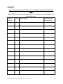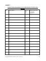
1
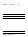
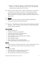
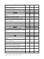
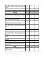
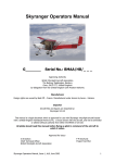
Skyranger Operators Manual G_______ Serial No.: BMAA/HB/_ _ _ Approving Authority British Microlight Aircraft Association The Bullring, Deddington, Banbury Oxon, OX15 0TT, United Kingdom by delegation from the United Kingdom Civil Aviation Authority Manufacturer Design rights are owned by Best Off – France. Manufactured under licence by Aeros – Ukraine. Importer Aircraft Kits and Spares are imported by: Skyranger UK Ltd This manual is a legal document which is approved for use with Skyranger microlight aircraft issued with a United Kingdom Homebuilt Permit to Fly. It must remain with the aircraft, and not be amended or altered without authority from either the BMAA or UK CAA. All pilots should read this manual before flying as pilot in command of the aircraft to which it refers. Approved for issue:B J Syson P M Dewhurst Chief Technical Officer Project Test Pilot British Microlight Aircraft Association Skyranger Operators Manual, Issue 3, Feb 2011 1 Contents 1. Introduction ................................................................................................................ 4 2. Description of the Aircraft ........................................................................................... 5 3. Limitations .................................................................................................................. 6 4. Flying the Skyranger.................................................................................................... 8 5. Performance .............................................................................................................. 18 6. Emergencies.............................................................................................................. 19 7. Rigging and De-rigging ............................................................................................ 21 8. Weight and Balance ................................................................................................... 22 9. Maintenance .............................................................................................................. 23 10. Repairs .................................................................................................................... 37 11. Vital Statistics ........................................................................................................ 38 Annex A The Microlight Airworthiness Approval Note recommending issue of a permit to fly Annex B Engine Manual Annex C Weight and balance report for this aircraft (form BMAA/AW/028). Annex D Minor modifications fitted to this aircraft (MinMods) Annex E Major modifications fitted to this aircraft (MAANs) Annex F Instructions and Manuals for other devices fitted to this aircraft Skyranger Operators Manual, Issue 3, Feb 2011 2 TABLE OF AMENDMENTS Amendment No Date incorporated Skyranger Operators Manual, Issue 3, Feb 2011 Signed 3 1. Introduction 1.1 The Skyranger is a three-axis microlight aeroplane, it was certified in the United Kingdom to the requirements of British Civil Airworthiness Requirements (BCAR) Section S issue 2; which at the time of writing is arguably the highest airworthiness standard in the world which is applied to microlight aircraft. 1.2 This manual is not intended to teach you to fly the aircraft, or to build it. Learning to fly should be accomplished under the supervision of a light aircraft or microlight flying instructor experienced on the type. At time of writing a flying instructor can only receive renumeration for flying instruction using an amateur built aircraft when teaching the sole owner (includes spouse and immediate family members) for the grant of a licence to fly. A separate build manual exists to instruct you in building a Skyranger from a kit. 1.3 What this manual will do, is provide the information which a qualified pilot requires to safely fly this aircraft (although a conversion by an instructor, familiar with the type is strongly recommended), and to carry out routine maintenance and minor repairs. Manuals exist for this aircraft for use overseas which also include guidance on fitting modifications to the Skyranger; all modifications to a British Skyranger must be approved by either the British Microlight Aircraft Association, or the UK Civil Aviation Authority. In general, the BMAA offers the cheapest and most straightforward route for approving modifications. 1.4 The licenses which would be required to fly this aircraft are either a JAR PPL SEP, UK PPL (A) with SEP or Microlight ratings. UK NPPL with microlight rating or NPPL SSEA with differences training for microlight aircraft. Pilots with microlight ratings trained for Flexwing aircraft should carry out differences training for 3 Axis control systems before attempting to fly this aircraft. Holders of the JAR or UK PPL(A) with Sep ratings are strongly recommended to carry out differences training for microlight aircraft. 1.5 This aircraft must be operated using two separate logbooks. One for the airframe and one for the engine (or the BMAA combined logbook, reference BMAA/AW/036). All entries must be made in the logbook in ink and within 7 days. If the aircraft is fitted with an in-flight Skyranger Operators Manual, Issue 3, Feb 2011 4 adjustable propeller, a separate logbook must also be held for that; it is recommended that CAP400, which is issued by the CAA and available from most pilot shops is used for this purpose. 2. Description of the Aircraft 2.1 Ancestry. The Skyranger was conceived by Philippe Prevot of Best Off Manufacturing, France, in 1991. The first 200 examples were manufactured under licence by Synairgie between 1994 and 1998. The manufacture of the Skyranger was moved to Aeros in the Ukraine in 1998, incorporating many developments in the design. 2.2 Construction. The Skyranger is predominately constructed of pinjointed straight aluminium tubes covered with pre-sewn polyester fabric. 2.3 Flying Controls 2.3.1 Pitch control is effected by fore-aft movement of the central stick, with movement transmitted to a conventional elevator through cables. 2.3.2 Pitch trimming is effected by a hand-operated lever mounted above the starboard seating position, with movement transmitted through cables to a trim-tab on the starboard elevator. 2.3.3 Roll control is effected by sideward movement of the central stick, with movement transmitted through cables to part-span, differentialmovement ailerons. 2.3.4 Yaw control is effected by dual-control foot pedals, with movement to the rudder transmitted through cables. 2.3.5 Braking is effected by hand-operated hydraulic disc brakes. 2.3.6 The undercarriage is of tricycle arrangement, with nosewheel steering effected by movement of the dual-control rudder pedals. 2.3.7 Flaps are lowered in two stages by lifting a hand-operated lever located between the seats whilst gripping an integral latching lever. Skyranger Operators Manual, Issue 3, Feb 2011 5 3. Limitations 3.1 Introduction This section includes the basic operating limitations for the Skyranger. The full limitations are contained in Homebuilt Aircraft Data Sheet (HADS) HM4, which is used by the Inspector at Annual Permit renewal to ensure, amongst other things, that the correct limitations are placarded in the cockpit. 3.2 Units When noting limitations, it is important to ensure that the limitations which you are using use the same units and calibrations as the instruments in the cockpit. The limitations shown below use knots CAS (Calibrated Airspeed); your aircraft may have an instrument in mph, and in any case will read IAS (Indicated Airspeed). The difference between IAS and CAS is basically the accuracy of your Pitot-static system. The IAS limits for your aircraft were determined when the aircraft was test flown, and are shown in Annex A to this manual. There will also be a placard in the cockpit, however space is allowed below for you to insert the IAS limitations and calibration details for your aircraft. IAS Calibration Card for Skyranger G-_______. Kn CAS 33 36 (Calibrated) Vso VS1 40 50 53 55 60 min climb approach Best speed Glide sink 65 66 72 Vfe Va 80 90 100 108 Vne IAS (Indicated) Unless all errors are less than 2 knots, a copy of this calibration card must be displayed in the cockpit near to the ASI. 3.3 Operational Limitations 3.3.1 The Skyranger must only be flown in day VMC conditions, with sight of the surface. It may not be flown over built up areas except in an emergency or on an approach to land at a government or licensed aerodrome in accordance with normal aviation practice. Skyranger Operators Manual, Issue 3, Feb 2011 6 3.3.2 The Skyranger is certified to a "permit to fly" standard. This prohibits aerial work. 3.3.3 This aircraft is certified to a UK only standard, this means that permission is required from the host country to fly it overseas. However a reciprocal agreement for homebuilt aircraft means that no permission is required for flights to other ECAC (European Civil Aviation Conference) member states. 3.3.4 The minimum instrumentation required will depend on the engine fitted. Details for each is specified in the type Homebuilt Aircraft Data Sheet (HADS) HM4. Latest issue of which is available on the BMAA website. 3.3.5 It is recommended that the Skyranger is not flown where a crosswind component above 15 knots is predicted. 3.3.6 Do not fly above 10,000ft standard pressure altitude without the use of personal oxygen. 3.3.7 Do not fly if any ice is present on the airframe. Performance, stability and handling will all be degraded with dangerous consequences. Do not fly the aircraft into known icing conditions. 3.4 Flight Limitations and key performance speeds 3.4.1 Never exceed speed, Vne, is 108 kn CAS [ IAS] 3.4.2 Manoeuvring speed, Va is 72 kn CAS [ IAS] 3.4.3 Flap limiting speed, Vfe is 66 kn CAS [ IAS] 3.4.4 Door open limit speed is 72 kn CAS [ IAS] 3.4.5 Speed for best rate of climb 53kn CAS [ IAS] 3.4.6 Speed for best climb angle 45kn CAS [ IAS] 3.4.7 Maximum Bank angles are 60° either way. 3.4.8 Maximum Pitch attitudes are 450 nose up and down from the horizontal 3.4.9 Normal acceleration limits are +4g / -2g. Skyranger Operators Manual, Issue 3, Feb 2011 7 3.4.10 At least 55kg (121lb / 8 stone 9lb) must be in the cockpit for flight, no more than 120kg (264lb / 18stone 12lb) may be carried in each seat. 3.4.11 Maximum Take-off weight is 450kg. 3.4.12 Aerobatics and deliberate spinning are prohibited. 3.5 Engine Limitations The limitations for the engine are contained in Annex B, they are also placarded in the cockpit. 4. Flying the Skyranger 4.1 Pre-Flight Inspection Pre flight inspection – Check A, is detailed in the maintenance section 4.2 Starting 4.2.1 Before starting the engine ensure that the max takeoff weight will not be exceeded (from fuel/weight placard). 4.2.2 The BMAA standard manual pre-start checks [STAIP] are recommended. The actual starting procedures for a particular engine are contained in Annex B to this manual. The STAIP checks are :Security Aircraft, Crew, Equipment, Secure, brakes ON. Throttles full and free, and closed, choke set as required. Area all around and behind aircraft clear. Ignition mags ON. Prop Shout ‘clear prop’, pause then start the engine. Once the engine is running set the recommended warm up RPM and slowly remove the choke. 4.3 Taxying 4.3.1 Before taxying ensure that the engine has run for at least 2 minutes from cold. Do not use high RPM until the engine has reached its minimum flight operating temps. Skyranger Operators Manual, Issue 3, Feb 2011 8 4.3.2 Taxy at no more than a brisk walking pace, somewhat less if the surface is rough. Steering is effected through the rudder pedals which are linked directly to the nosewheel. The turning circle normally is around 20 feet in diameter (at the aircraft centreline). 4.3.3 Microlight aircraft are easily blown over in winds over 25knots. It is imperative that when taxiing in strong winds the correct control placements are used. When the wind is from the forward quarters hold the stick into wind and the elevator neutral. When the wind is from the rear quarters the stick should be positioned away from the wind and the elevator held down. 4.3.4 Taxy checks When taxying check: 4.4 Brakes functioning Compass moving when aircraft turned Slip ball moving when aircraft turned Engine temps warming, no limits exceeded Pre take-off checks (vital actions) Prior to take-off, it is recommended that the following pre takeoff check is used. This check is a derivation of the mnemonic CHIFTWA as used in many BMAA schools. Position the aircraft into wind, brakes held on Set recommended warm up RPM C - Controls Check controls for full and free movement (Note, a knee board worn on the pilots right leg may give control restriction) Check visually that the controls are moving in the correct sense H - Harness and Hatches Check harnesses and hatches are secure, no loose objects I – Instruments and engine Check flight instruments are set and serviceable Skyranger Operators Manual, Issue 3, Feb 2011 9 Check engine instruments are serviceable, minimum operating temps Check choke is OFF Set recommended RPM and check mag drop Check for smooth idle Increase power to maximum that the brakes will hold for at least 10 seconds Check engine indications normal Reset recommended smooth fast idle RPM F – Fuel and Flaps Check fuel tap is ON Check contents sufficient for flight Cycle flaps and check symmetrical operation, detent operation Set flap as required T - Trim Check trim set for takeoff W – Wind (and emergencies) Check wind speed and direction Consider emergency actions A – All clear Confirm all clear on approach R/T call if required and line up on runway 4.5 Take-off 4.6 Normal 4.6.1 For a non performance takeoff, into wind, flaps can either be left in the fully up –CR (cruise) position, or with the first stage – TO (takeoff) position. Skyranger Operators Manual, Issue 3, Feb 2011 10 4.6.2 When lined up and rolling straight smoothly apply full power. Keep straight with rudder, ailerons neutral and with the elevator slightly up to reduce the weight on the nosewheel. 4.6.3 When the airspeed rises to 45 knots CAS [ IAS] rotate and lift off and adopt a shallow climb attitude. Allow the airspeed to rise to 60 knots CAS [ IAS] and adopt a climbing attitude to hold this airspeed. 4.6.4 When above 200 feet AGL the airspeed can be reduced to 53 knots CAS [ IAS] if a greater climb rate is required, and the flaps selected to CR. The power can also be reduced a little for noise abatement if required. When the flaps are retracted there will be a slight tendency for the aircraft to pitch up, which will require a gentle push on the stick to maintain a constant airspeed. Therefore after the flap change re trimming may be required. 4.6.5 When in the climb, due to the excellent climb rate – especially with the 80hp and above engine options, the nose is high and may obscure forwards view. Therefore it is recommended to periodically weave or lower the nose to clear the blind spot. For prolonged ascents a cruise climb at reduced power setting and slightly higher airspeed is recommended and will increase forwards field of view. 4.7 Short takeoff 4.7.1 For a short takeoff select first stage, (TO), flap. Start from as close to the beginning of the field as possible. Hold on the brakes as power is increased to full. When power is full or if the aircraft starts to ‘creep’ forwards, release the brakes. Elevator position should be neutral (smooth surfaces only) or slightly up. 4.7.2 When the airspeed rises to 40 – 45 knots CAS [ IAS] rotate and lift off. When airborne allow the aircraft to accelerate to 45 knots CAS [ IAS] for best obstacle clearance. Be aware that at this speed prompt action will be needed to lower the nose and obtain glide speed in the event of power loss. 4.7.3 When clear of obstacles allow the aircraft to accelerate to 53 knots CAS [ IAS], and at 200 feet AGL select CR flap. Skyranger Operators Manual, Issue 3, Feb 2011 11 4.7.4 It is important to always pick an abort point before attempting to take off from a short field. If the aircraft approaches the abort point before lifting the takeoff should be aborted by fully closing the throttle and braking firmly. 4.8 Soft field takeoff 4.8.1 Select first stage (TO) flap. Avoid stopping the aircraft whilst entering the runway and roll into the takeoff run. Hold full up elevator until the nosewheel lifts and then try to balance the aircraft in the rotate attitude whilst speed is increased. This will help reduce rolling resistance and keep overall drag to a minimum. 4.8.2 Allow the aircraft to lift off at around 40 knots CAS[ IAS] , and then carefully allow the aircraft to accelerate to 53knots CAS [ IAS] in ground effect before adopting the climbing attitude. At 200 feet AGL select CR flap. 4.9 Crosswind takeoff 4.9.1 The maximum demonstrated takeoff crosswind limit of the Skyranger is a component of 15knots. Pilots are advised to avoid crosswind components of greater than 10 knots until very experienced on the Skyranger. 4.9.2 Select O (CR) flap. Start the takeoff roll with the stick held fully into wind and the elevator neutral. Pressure may be required on the rudder pedals to steer straight. 4.9.3 Allow the aircraft to accelerate. The amount of aileron can be reduced if there is a tendency to lift the downwind wheel. Keep the elevator neutral until the speed reaches 53knots CAS[ IAS], then cleanly rotate and lift off. 4.9.4 As the aircraft lifts off adopt a shallow climb attitude. Gently yaw the aircraft into wind to set up the required drift angle, and centralise the ailerons and centralise the balance ball. 4.10 Landing 4.10 Normal landing 4.10.1 Generally the Skyranger should be landed from an approach speed of about 55knots CAS [ IAS], although in turbulent conditions handling can be improved by increasing this by 5-10 knots. Full flap Skyranger Operators Manual, Issue 3, Feb 2011 12 (LD) position should be selected. As flap is selected a gentle pull on the stick will be required to maintain constant airspeed. Therefore re trimming will be required. 4.10.2 Roundout should be initiated around 15-20 ft and hold-off 2-3 ft above the runway. 4.10.3 Pilots transitioning from more traditional lower performance microlight aircraft should be aware that if the airspeed is allowed to increase on the approach then the aircraft may exhibit considerable float during the hold off period and this may cause a tendency to ‘balloon’ and will cause more runway than expected to be used. 4.11 Short field landing 4.11.1 Select full flap (LD) position, and set up a powered approach at around 45 – 50 knots CAS[ IAS]. Use power adjustments to control the flight path and rate of descent whilst accurately maintaining airspeed with elevator. If tall obstacles are present on the approach, then transition into a glide approach once clear past them. Take care however to maintain airspeed during this phase. 50 knots CAS [ IAS] is recommended as the minimum for a glide approach at max takeoff weight. 4.11.2 When round out height is reached close the throttle fully and round out. Perform a brief hold off and land. Brakes can be used to shorten the landing roll if required. Take care not to brake too sharply on rough or soft surfaces. Braking efficiency is at its greatest if the elevator is applied fully up after touchdown and speed has decayed below flying speed. 4.11.3 Accurate airspeed control is the key to short field performance and pilots new to the Skyranger must practice until this is achieved to be able to land in the published distance. 4.12 Soft field landing 4.12.1 Fly the approach as in 4.11.1 above. 4.12.2 Fully hold off and try to touch down gently and as slow as possible. During the ground roll avoid braking and progressively apply full up elevator to keep the nose wheel up for as long as possible. Continue to hold up elevator when the nose wheel is on the ground. Skyranger Operators Manual, Issue 3, Feb 2011 13 4.13 Cross wind landing 4.13.1 The Skyranger has a maximum demonstrated crosswind component of 15 knots. Cross wind components above 10 knots should not be attempted other than by experienced pilots fully familiar with the type. 4.13.2 Either O (CR) or first stage (TO) flap can be selected. Fly a powered approach at a little higher airspeed than normal – around 55 – 60 knots CAS[ IAS]. Initially crab the approach to remain in balance and on centreline. 4.13.3 During the final stages of the approach lower the into wind wing a little and rudder the fuselage to align with the runway. Round out and hold off like this and touchdown into wind wheel first. Try to land after a short hold off without allowing the airspeed to decay too much. This will assist in maintaining good control response. 4.13.4 As with all crosswind landings the aircraft must still be accurately ‘flown’ whilst on the ground. Initially the aircraft will touchdown into wind main wheel first. Progressive aileron deflection should applied into wind as the speed decays during the ground roll to keep the aircraft on one wheel and gently lower the downwind wheel as airspeed decays and aileron authority is reduced. The aircraft will need to be accurately steered straight down the runway with rudder during this process. The nose gear should be held off initially and gently lowered before rudder authority reduces too far and aerodynamic directional control is lost. As the nose wheel touches down rudder will have to be straightened to avoid a steering snatch due to the rudder deflection applied against the crosswind. 4.13.5 When the nose wheel is down aileron will still need to be applied against the crosswind and neutral or light forwards elevator pressure should be applied to ensure adequate steerage from the nose wheel and avoid yawing into wind. 4.14 Cruise The Skyranger has a large range of cruise speed. At the higher values fuel consumption will be correspondingly higher. Cruise is set up in the normal way by selecting the required attitude and power and trimming off any residual pitch forces. Skyranger Operators Manual, Issue 3, Feb 2011 14 4.15 Turning 4.15.1 Turning the Skyranger is accomplished in the standard manner. In common with most microlight aircraft the Skyranger requires some rudder co ordination to maintain balance when rolling into and out of a turn. 4.15.2 As with any other aircraft, the stall speed will increase with bank angle. The stalling speed at 600 bank will rise to 51 knots CAS[ IAS], at max takeoff weight. 4.16 Flight in Turbulence The Skyranger has powerful controls and handles turbulence well. However, do not fly above the manoeuvre speed of 72 knots CAS [ IAS] in turbulence. Below this speed the worst thing a gust can do to you is stall the wing or one of the control surfaces. Above that speed, it is possible for strong gusts to overstress the aircraft. 4.17 Stalling During test flying of the UK prototype G-CBIV the following stalling speeds were recorded: VS1 – Stalling speed at max takeoff weight, forward CG and flaps up: 36kn CAS. VSO – Stalling speed at max takeoff weight, forward CG, full flap: 33kn CAS. These speeds should represent the worse case in normal service. Lower takeoff weights and more rearward CG will lower the stalling speed – but not by much! Pilots should also remember that stalling speed increases during turns and manoeuvres. Any ice on the aircraft will also increase stalling speeds – never takeoff with ice present on the aircraft. 4.17.1 Slow flight characteristics Slow flight indications include: Lightening of controls accompanied by reduced effectiveness Reduced airflow noise (most noticeable at low power settings) High nose attitude (most noticeable at high power settings) Rearwards position of control stick and back pressure Skyranger Operators Manual, Issue 3, Feb 2011 15 Strong pitch buffet as the incipient stall is entered A tendency to roll or wing rock accompanying the buffet To recover normal operating airspeed at the slow flight stage, simply move the stick forwards and apply power. 4.17.2 Wings Level, Power Off The aircraft can safely be stalled at a deceleration rate of up to 3kn/s. Max pitch attitude is 45 0, and stall warning is given about 5 knots above the stall by buffet. Stall is normally marked by a mushing descent in heavy buffet or nose drop. 4.17.3 Recovery is effected in the standard manner by moving the stick forwards to reduce angle of attack and simultaneously applying full power. The nose can then be raised as soon as the airspeed is building past 45 – 50 knots CAS [ IAS]. Height loss between stall and recovery, if well executed, is around 50 feet ft if power is used, or around 100 feet to establish a steady glide if power is not used. 4.17.4 Wings Level, Power On Characteristics are similar to the power off case. An additional warning of the approaching stall is the attitude of the aircraft. With full power set the aircraft stalls at a very high nose attitude. 4.17.5 Because of the increased slipstream and torque effect at high power settings considerable rudder deflection may be required to keep in balance as the stall is approached. Stalling out of balance can result in considerable wing drop. 4.17.6 Recovery is simply effected by moving the stick forwards to reduce angle of attack. Any tendency to wing drop should be countered by application of opposite rudder sufficient to prevent further yaw towards the dropping wing. These two actions should be performed simultaneously. 4.17.7 In Turning Flight Stalling speeds are increased with bank angle, in the manner normally expected. The Skyranger often has the characteristic of rolling towards wings level as the stall occurs. Recovery is standard. Move the stick forwards to reduce angle of attack and apply power. Simultaneous opposite rudder should be applied against any rolling tendency. Once the aircraft is safely above the stalling speed co-ordinated aileron and rudder can be used to level the wings. Skyranger Operators Manual, Issue 3, Feb 2011 16 4.18 Aerobatics Aerobatics are not permitted in this aircraft. 4.19 Departures from Controlled Flight 4.19.1 The Spin Deliberate spinning of the Skyranger is prohibited. However, it is possible through mishandling of the aircraft to inadvertently enter a spin, either through stalling the aircraft in a turn, or by failing to keep the rudder pedals straight at the point of stall. Should this happen, the spin can be seen by a steep nose-down pitch attitude (about 45° nose down) and the aircraft rapidly yawing in one direction. Some higher than normal 'g' forces may also be experienced. Should this occur, close the throttle and centralise the stick and rudder pedals immediately. The aircraft should stop turning almost immediately and be established in a steep nose down attitude with the airspeed rising rapidly. At this point gently ease out of the dive, and then normal flight can be resumed. 4.19.2 Other Departures Other departures from controlled flight are likely either to be due to damage to the aircraft, or hazardous flying conditions. In either case, land as soon as possible and examine the aircraft, particularly the flying controls, for any damage. 4.20 Flight with doors open If fitted with the two piece door option the Skyranger may be flown with the top half of the door open. The maximum speed for flight with the doors open is 72kn CAS [ IAS]. 4.20.1 When the doors are opened in flight they must be latched on the wing mounted hooks. Failure to do this can result in the door unexpectedly slamming shut during flight out of balance (sideslips). 4.20.2 Pilots should be aware that as the doors are opened the aircraft will experience a tendency to pitch up slightly and re establish trim some 5kn or so slower. 4.20.3 The Skyranger exhibits greater directional stability when flown with the doors open. This then requires slightly more rudder input to maintain balance with the engine running at full power in the climb. 4.20.4 Climb and glide performance is slightly reduced when flying with the doors open. Stall and spin characteristics remain unchanged. Skyranger Operators Manual, Issue 3, Feb 2011 17 5. Performance 5.1 The following data was obtained in the original UK prototype, G-CBIV. Changes from this data for your particular aircraft will be at Annex A. When using the data for planning purposes, apply sensible safety factors, such as are contained in CAA Safety Sense leaflet 7B (aircraft performance), part of which is reproduced here by kind permission of the CAA. 5.2 The best climb speed is 53kn CAS [ IAS]. When selecting a climb speed, always remember that should anything go wrong, more speed gives you more time to sort your problems out. Although climb performance may change between aircraft, the best climb speed should not. Specific performance figures for your aircraft will be in Annex A. 5.3 The best glide speed is 60kn CAS [ IAS], at which a glide ratio of around 9 to 1 may be expected. Flying a little slower at 50kn CAS [ IAS] will give the minimum descent rate (min sink) of around 550FPM. 5.4 Cruise performance Because microlight aircraft are very strongly affected by weight, engine condition, propeller matching, wind and air temperature, it is very hard to give any reliable information concerning the cruise performance of the Skyranger. The captain is encouraged to plan very conservatively until sufficient experience is gained of the fuel consumption and cruising speeds at the conditions in which he or she normally fly the aircraft. 5.5 Takeoff performance Take-off performance for short dry grass for your aircraft is contained in Annex A. 5.5.1 Using the figures above, the following additional safety factors should be applied to the distance to clear a 15metre obstacle (taken from CAA GA Safety Sense leaflet 7B). If unsure, always use these factors to ensure you have sufficient take-off distance available. Per 1000 ft runway height above Sea Level Multiply by 1.1 Per 10°C increase in temperature above 15°C Multiply by 1.1 Per 2% uphill slope Multiply by 1.1 Soft ground or snow or wet grass Multiply by 1.25 Skyranger Operators Manual, Issue 3, Feb 2011 18 If it is very soft (or wet), or the snow is more than 1”deep Multiply by 1.6 If you have to take-off with a tailwind Multiply by 1.2 for every 4 knots of wind Now to be sure, multiply by 1.33, to take into account that you may not fly the aeroplane as well as the company test pilot did when he worked out the values in the manual. 5.6 Landing performance Landing performance for short dry grass for your aircraft are contained in Annex A. Using the figures above, the following additional safety factors should be applied to the distance to clear a 15metre obstacle on the approach (taken from CAA GA Safety Sense leaflet 7B). If unsure, always use these factors to ensure you have sufficient runway to avoid using the considerately provided hedge at the far end of the runway. For every 1000ft you are above sea level multiply by 1.05 For every 100C above 150C air temperature multiply by 1.05 For every 2% of downslope multiply by 1.1 If the runway is tarmac or concrete multiply by 1.2 If the ground is soft, or there is snow or wet grass multiply by 1.25 If the ground is very soft (or wet) or if the snow is more multiply by 1.6 than 1” deep If you have to land with a tailwind multiply by 1.2 for every 4 knots of wind Now to be sure, multiply by 1.33, to take into account that you may not fly the aeroplane as well as the company test pilot did when he worked out the values in the manual. 6. Emergencies 6.1 Engine Failure Before Take-Off (aborted takeoff) Close throttle, apply brake, switch off. 6.2 Engine Failure After Take-Off (EFATO) Lower nose, to establish an approach speed of at least 50 kn CAS [ IAS] land straight ahead or near to straight ahead, DO NOT ATTEMPT TO TURN BACK from below 500ft. Skyranger Operators Manual, Issue 3, Feb 2011 19 6.3 Engine Failure In Flight Lower nose, maintain 50 kn CAS [ IAS] the minimum sinking speed. If it is required to glide a distance to the nearest suitable field then 60 kn CAS [ IAS] will give the best glide speed, fly a little faster in a head wind to maximise distance and a little slower with a tail wind. Select a landing site, make emergency radio call if time permits, as time permits check for possible reasons for engine failure and attempt re-start (e.g. ignition switches, fuel cock, lack of fuel pressure), if field is flat land into wind, otherwise uphill. Apply braking only if it is essential to stop within the distance available, and never before all 3 wheels are on the ground. 6.4 Engine Fire in Flight Close fuel cock, open throttle fully, make emergency call if time permits, when engine stops turn off mag switches and master, treat as engine failure in flight. Vacate aircraft as soon as possible after landing. 6.5 Fire in the cockpit Switch off all electrical devices (not the ignition unless there is an engine fire also), close heater vent, open fresh air vents, land immediately and vacate the aircraft. 6.6 Emergency Landing on Water Try to land into wind with as high a nose-up attitude as possible. Before impact, pilot and passenger must be prepared to release their harnesses, it may also be beneficial to release the doors before impact. If wearing lifejackets, do not inflate them until outside the aircraft. Note that it is very hard to judge height above water. 6.7 Emergency Landing in Trees Ensure harness(es) tight, try for low bushy trees as far as possible. Try to impact with as steep a nose-up attitude as possible. 6.8 Inadvertent Flight in Hail or heavy rain Reduce power to avoid propeller damage, fly out of the weather as soon as possible. 6.9 Inadvertent Flight in Icing Conditions Fly out of conditions as soon as possible, land as soon as possible. 6.10 Use of Ballistic Parachute (if fitted) Tighten harnesses, fuel cock OFF, ignition OFF, pull handle, make emergency radio call if radio carried. [Note, if a BRS is fitted to this aircraft, the BRS manual will be annexed to this manual.] Skyranger Operators Manual, Issue 3, Feb 2011 20 7. Rigging and De-rigging 7.1 To attach the wings to the Skyranger: With the wing tip raised to approximately the rigged height, slide the wing root into place to engage in the root brackets. Insert the wing root fixing bolts Attach the lift struts and jury struts Tighten all attachment bolts and insert safety rings Connect flap pushrod Connect Pitot line Connect aileron cables Ensure aileron cables are crossed as per placard in cockpit on central upright. Final inspection of all nuts and bolts, cable routing and attachments 7.2 7.3 To remove the wings from the Skyranger: Disconnect aileron cables Disconnect pitot line Disconnect flap pushrods Remove safety rings from lift strut bolts Remove nuts from lift strut bolts and spar bolts Support wing tip Remove lift struts Remove spar bolts (wing root) Slide wing outwards until spar is clear of cabin. The tail plane is not designed to be a regular de-rig item, however it may be removed for long distance trailering, as may the rudder. When re assembling these parts replace all Nyloc nuts that were removed for disassembly. Skyranger Operators Manual, Issue 3, Feb 2011 21 7.4 Use of wing fold mechanism Use of the optional Skyranger wing fold mechanism is detailed in the wing fold instructions which should be put in Annex G 8. Weight and Balance 8.1 So long as it is kept within the placarded operating limits, and no unapproved modifications have been made since construction (including the alteration of ballast), the Skyranger can be flown with any permitted fuel, pilot and passenger weights without falling outside of its permitted CG limits. However, pilots should be aware that stick forces and displacements will become lighter with aft CG (typically a heavy crew and full fuel) and heavier with forward CG (typically low fuel, light pilot only). Also at aft Cg, the hands off stability will be reduced. The aircraft will have an increased tendency to lower damping in Phugoid motion (hunting in speed and height when disturbed), which will be most noticeable in turbulent conditions. Flying outside of the permitted CG limits at either extreme is potentially dangerous and should not be attempted in any circumstance. 8.2 CG Datum The Skyranger CG datum and limits are contained in the HADS 8.3 CG moment arms The moment arms of the seats, fuel tank(s) and other items are shown in the HADS HM4 and in the Weight and CG report at Annex C. 8.4 Weighing The Skyranger will have been weighed when first built, and must be re-weighed at intervals as laid down by the BMAA and CAA (typically every 5 years or when it is modified or repaired). 8.4.1 Weighing should be carried out by a BMAA 3-axis inspector or Technical Team member. A copy of the W&CG report must be retained in this manual at Annex C. Also at each weighing, details of the weighing must be entered in the aircraft logbook. Full instructions on how to weigh a microlight aircraft are contained in BMAA technical information leaflet TIL 012, and specifically for the Skyranger in HADS HM4. Skyranger Operators Manual, Issue 3, Feb 2011 22 9. Maintenance 9.1 Introduction This manual details recommended maintenance. However maintenance requirements will depend upon conditions of storage and type of use. Examples of harsh use may include: Storage outside Use near salt water Regular use from unprepared rough fields Regular transport by trailer Learning to fly In such cases more regular inspections and component replacement may be required in order to keep the aircraft in an airworthy condition. 9.2 Who may carry out maintenance, and who’s responsibility is it? 9.2.1 The Skyranger has been designed and conceived to be maintained by a person without specific training in mechanics. However some mechanical experience is desireable, and persons with limited mechanical capability should limit themselves to the simple maintenance actions and engage suitably skilled persons to undertake the more complex tasks. No specific qualifications are legally required for persons carrying out maintenance work on UK Microlight Aircraft. 9.2.2 The Owner is essentially the ‘maintenance manager’ and must assume responsibility for ensuring the maintenance actions are carried out as and when required in order that the aircraft may remain in an airworthy condition. As such the owner must be thoroughly familiar with this maintenance manual, and not hesitate to take advice from their local BMAA inspector, professional maintainer, and / or the aircraft importer on any points that are not immediately clear. 9.3 Recording and certifying maintenance 9.3.1 All maintenance actions should be recorded in the aircraft airframe and engine log book(s). Separate worksheets and invoices for parts / work, should be kept in a file that can be referenced in conjunction with the logbook entries. Skyranger Operators Manual, Issue 3, Feb 2011 23 9.3.2 Each logbook entry detailing maintenance should be accompanied by a signature of the person or persons that have carried out the work. Any work that is ‘flight critical’ must have a second signature (in addition to the person that has carried out the work) to certify that correct reassembly has been carried out. This must be done by a ‘qualified person’- the definition of such a person is anyone that the owner deems qualified for the task. Another pilot familiar with the type or similar type, a BMAA or LAA inspector, or a professional maintainer, are examples of persons that could be considered ‘qualified’ for this task. Examples of tasks that are considered ‘flight critical’ are: Dis/ reassembly of primary structure (not re/derigging). Maintenance by replacement of primary structure Maintenance by replacement of control systems 9.4 Sourcing parts 9.4.1 Unique airframe parts must be purchased from the manufacturer, or another organization approved by the BMAA for manufacturing such parts (usually if the manufacturer has ceased trading). Some parts may be unique to the UK approved model, so this must be verified – normally by supply from the UK agent. 9.4.2 Non unique parts may be sourced from other suppliers. However they should be equivalent in terms of specification and dimension. If there is doubt, then there is no doubt – they should not be used. 9.5 Engine maintenance This should be carried out in accordance with the engine manufacturer’s specific maintenance schedule for the type and model of engine. 9.6 Inspections and when to carry them out 9.6.1 There are four types of routine inspections: 1. Check A – this is a daily inspection. A sub version of this is a subsequent preflight inspection, which may be slightly less detailed. 2. Check B – 25 hour / 3 month inspection (whichever comes sooner). This inspection may be extended by 10% (2.5 hours). 3. Check C – 50 hour / 6 month inspection (whichever comes sooner). This inspection may be also be extended by 10% (5 hours). Skyranger Operators Manual, Issue 3, Feb 2011 24 4. Annual – Once per year timed to co-incide with the annual permit inspection or 100 hours (whichever comes sooner) This inspection may be also be extended by 10% (10 hours). 9.6.2 These hours are airframe hours – which are flight hours. If the aircraft is operated from a rough surface then it is recommended airframe hours are recorded from start of taxying, to finishing taxying at the end of the flight. For convenience owners may choose to base times on engine hours. 9.7 Check A 9.7.1 Engine - carry out an engine pre-flight inspection following the instructions contained in the engine manual. 9.7.2 Aircraft - The following is a brief summary of the minimum pre-flight inspection. If you are unsure, it does no harm to increase the number of items on your inspection. Inside the Cockpit: Ignition switches OFF Condition of choke and choke cable Condition and security of all flying controls Check condition of all instruments Check harnesses are properly fitted and not frayed. Check seats are secure. Check fuel filter is clean. Check sufficient fuel for the planned flight. Check wing leading and trailing edge bolts secure Underside If the aircraft has not flown within 24 hrs, drain a small amount of fuel from the drain tap using a standard tool and check for water. Engine bay Remove cowling Check all items as in engine manual at Annex B Check security of all electrical connections Check prop bolts protruding from securing nuts Skyranger Operators Manual, Issue 3, Feb 2011 25 Generally look for any fluid leaks or loose fastenings Check condition of engine mounting rubbers and bolts Check firewall security – not chafing any structure, secure and sealed to cowlings. Replace the cowling and all securing screws Starting from the nose, inspect Condition of the propeller: no nicks or cracks Condition and security of the spinner, if fitted Condition and inflation of the nose wheel tyre Condition of noseleg Security of the nose wheel spat and fairing Security of the engine cowling Moving down the starboard side of the aircraft and along the starboard wing, inspect Static vent is clear of obstructions Condition of door, hinges and latches Starboard undercarriage leg undistorted Undercarriage drag strut and shoes secure Tyre condition and pressure Security of wheel spat Check for evidence of hydraulic leaks Security of wing strut lower attachment bolt Jury strut brackets Wing struts and jury struts straight Security of upper wing strut attachments Through the inspection panel in the lower surface, check the condition of the aileron pulleys and cables and internal wing structure. General condition of leading edge, wing tip area and covering Aileron movement and hinges, attachment of cables and control horn condition Flap, hinges, and security of actuating rod attachment Condition of wing covering and security of battens Moving towards the tail, inspect Condition of covering on tail cone. Security of horizontal tail mounting bolts and covering lacing Elevator and hinges, horns and cables Trim-tab, horn and cables Skyranger Operators Manual, Issue 3, Feb 2011 26 Rudder and hinges, horns and cables Condition of tail surface coverings General alignment of vertical and horizontal tail surfaces Condition of bracing wires and their terminations Moving forwards to the port wing, inspect Port undercarriage leg undistorted Undercarriage drag strut and shoes secure Tyre condition and pressure Security of wheel spat Check for evidence of hydraulic leaks Security of wing strut lower attachment bolt Jury strut brackets Wing struts and jury struts straight Condition of wing covering and security of battens Flap, hinges, and security of actuating rod attachment Aileron movement and hinges, attachment of cables and control horn condition General condition of leading edge, wing tip area and covering Security of upper wing strut attachments Through the inspection panel in the lower surface, check condition of the aileron pulleys and cables and internal wing structure. Condition of door, hinges and latches Static vent is clear of obstructions Finally stand back and take an overall view looking for general symmetry. 9.8 Check B, C and Annual Check B Check C (25hrs/3 (50hrs/6 months) months) Annual (or 150 hrs) Fuselage Check all pressure instruments for cracks, leaks and x x x x x x x x x stiction Check all fuselage tubes for cracks, dents, corrosion or deformation Check all fasteners for security, condition and fretting Skyranger Operators Manual, Issue 3, Feb 2011 27 Check all bracing cables, for tension, security, fretting, x x x Check all plastic saddle washers for cracking. x x x Check operation of flying controls – friction, control x x x x x x x x x x x x x x x x x x x x x x x x x x and corrosion. cable tension and condition. Rotate control cable pulleys ¼ turn Check harnesses for security, condition and operation of buckles Check Seats, for security and condition, wear on support pegs. Check fuselage fairings and cowlings for security and condition Check doors for security and condition, cracks in lexan, operation of latches. Check windscreen for security and condition – cracks in lexan. Undercarriage Check main gear legs for distortion, security and condition. Check noseleg for distortion security and condition, free rotation Regrease nose leg (undo top bolt, and steering bar and x slide down to do this) Check wheels for general condition, security of rims to x x x x x x Spin wheels to check bearings x x Check brake discs and callipers for security, pads for x x hub, and rims for distortion. Check Tyres for tread, cuts, scores, perishing, correct inflation (26PSI) wear levels. Check operation of brake system, fluid levels and leaks. x x x Check condition and security of wheel spats (if fitted) x x x x x x Propeller Inspect blades for nicks and splits Skyranger Operators Manual, Issue 3, Feb 2011 28 Remove spinner and check hub for security and x x x x condition Check securing bolts torque Check blade pitch setting x Check spinner and back plate for security and condition x x x x x x Check tanks for security and condition x x Check fittings for perishing rubber bungs / leaks x x x x Fuel system Inspect inside tanks for dirt / contamination – clean if required Inspect all fuel pipes for perishing, abrasion and x security of connections Change fuel filter x Inspect system for leaks x x x Check operation of fuel tap x x x Check electrolyte level of battery (if applicable) x x x Check security of battery mounting, leaks, connections x x x Check all wiring for condition and security x x x Check condition of all switches x x x x x x x x Electrical security Wing Check spar tubes for straightness, dents, corrosion and fretting Check all cables and thimbles for tension, corrosion, fretting, fraying, kinking. Check all fasteners for condition and security x x x Check lift struts for straightness, dents, corrosion and x x x x x x x x x x x fretting, security and condition of fasteners Check jury struts for straightness, dents, corrosion and fretting, security and condition of fasteners Check aileron structure, and condition and security of hinges, operation and control cable runs and pulleys. Rotate aileron cable pulleys in wing ¼ turn Skyranger Operators Manual, Issue 3, Feb 2011 29 Check flap structure, and condition and security of x x x Lubricate aileron and flap hinges x x x Check coverings and stitching for condition, abrasion, x x x for x x x Check tailplane halves attached securely to fuselage – x x x x x x Check operation of elevator x x x Check hinges – condition and security x x x Lubricate hinges x x x Check fabric and stitching condition x x x Check condition and tension of bracing cables. x x x Check condition and tension of Elevator cables x x x Check security and condition of trim tab x x x Check operation of trim tab and hinge x x x Check trim tab springs for condition and security x x x Lubricate trim tab hinge x x x Check trim tab control cable for condition x x x x x x x x x Check condition and tension of rudder cables x x x Check condition and tension of centering bungee x x x Check condition of hinges x x x Lubricate hinges x x x hinges. Operation. Check return spring on detent lever. damage Tailplane and Elevators Check structure of tailplane and elevators, straightness, dents, corrosion. condition and securing of fasteners and mountings Check elevator joiner for condition, and security/ integrity between elevator halves (grasp each elevator and apply some torque pressure in opposition – there should be no movement) Fin and Rudder Check structure of fin and rudder for straightness, dents, corrosion Check forward attachment of fin – condition and security Skyranger Operators Manual, Issue 3, Feb 2011 30 Check rudder operation (push tail down to free x x x Check condition and security of fin extension x x x Check fabric and stitching condition x x x Complete maintenance actions as per engine manuals x x x Check fuel system – condition of fuel lines, security of x x x x x x x x x x x x x x x x x x x x x x x x x x Check engine mount bolts wire-locking. x x x Check engine cowlings for condition, security of x x x x x x nosewheel), no excessive friction, and centering on release Engine bay connections. Carburettor rubbers for bulges or splits. Air filters – security and condition Check oil system – condition of oil lines, security of oil cooler, Oil tank, oil filter, level and leaks Check water system – condition of hard and flexible water hoses, water radiator, header tank, overflow bottle level and leaks, Water carb heat (if fitted) Check exhaust system – security, springs, check for cracks, dents, blowing. Proximity to cowlings, fluid pipes. Lubricate exhaust ball joints Check heater components – security of heater wrap, ducting, valves and operation. Check electrical system – engine connections, security and condition. Spark plug connections, CDI unit security. Check engine mounting structure for condition and security. Check engine mount rubbers for excessive movement (see below) mounting fasteners, check fire resistant paint isn’t worn off areas. General Symmetry check – stand 5M in front and view for general symmetry – fin and tailplane alignment with wing, wing twist etc. Skyranger Operators Manual, Issue 3, Feb 2011 31 9.9 Component Life The following components have a calculated fatigue or wear life. They should be replaced at the following intervals: Lower Lift strut Bolts 500 Upper Lift strut bolts 1000 Leading and Trailing edge to fuselage 1000 attachment bolts Wing fold spar attachment pins 500 Control stick pivot bolt 1000 Control stick torque tube forward hinge bolt 1000 All Control cables 1000 9.10 Fabric 9.10.1 The Skyranger can be fitted with either Dacron or Xlam coverings. It should be noted that Dacron degrades more rapidly than Xlam when exposed to UV light, and therefore requires more care to ensure a long service life. 9.10.2 Prolonged outside uncovered storage is not recommended. 9.10.3 Covering fabric and its stitching can be tested with the BMAA approved ‘Bettsometer’. This will be done annually during its UK Permit to Fly renewal inspection. In addition it should also be done after each 100 hours of flight or after each 20 days of accumulated outside storage (such as resulting from touring use) – whichever accumulates the sooner. 9.10.4 The minimum Bettsometer test values for the Skyranger are: 9.11 Dacron 1000g Xlam 1360g All stitching 1360g Damage to fabric 9.11.1 Small tears in the fabric up to 30mm long, or abraded holes up to 15mm diameter, that are more than 50mm from a seam line, or can Skyranger Operators Manual, Issue 3, Feb 2011 32 be repaired using a self adhesive patch, if possible to both sides of the fabric – warmed gently with a hairdryer to melt the adhesive. 9.11.2 Single broken stitches can result in ‘running’, where a large area loses tension. Securing the broken end with a drop or two of glue will prevent this. 9.11.3 Any greater damage must be repaired using approved processes. These are detailed in BMAA TIL 015. 9.12 Cleaning lubricating and protecting the structure 9.12.1 Aluminium and steel airframe components and fasteners can corrode rapidly in certain adverse conditions. These include: Operation in a ‘marine’ environment (near the coast where salt can be in the air). Dust or dirt left on the structure for prolonged periods. Dampness for prolonged periods – especially dampness coupled with dirt or dust. 9.12.2 Always keep the aircraft clean. It pays to clean the aircraft after use before storage. But avoid putting the aircraft away wet in a closed hangar with reduced ventilation. 9.12.3 Proprietary car ‘wash wax’ cleaning products are generally suitable for washing. Pay particular attention to rinsing to ensure all traces of detergent are removed. 9.12.4 Particular care should be exercised cleaning Dacron fabric. We recommend ‘Starbrite Sail and Canvas Cleaner’. 9.12.5 For corrosion protection we recommend ‘ACF50’ ant corrosion fluid be liberally applied periodically to the airframe components. This can be applied to a cloth and rubbed on – much like a polishing operation. Use the aerosol directly to get in tight areas and exposed tube ends. Wiping away and dribbles and excess. 9.12.6 Exposed steel parts like wing strut ends, tailplane turnbuckles etc are recommended to be coated with a thin layer of grease. 9.12.7 Control surface hinges should be regularly lubricated – either with grease or oil. 9.12.8 Glassfibre parts can be polished after washing with wax polishes. Skyranger Operators Manual, Issue 3, Feb 2011 33 9.12.9 Lexan glazing is sensitive to product in order to remain clear and streak free. Flylight ‘Flies Off’ works well. ‘Plexus’ or ‘Plexicoat’ have also been found to be suitable. Warning - Fuel spillage or contact with Loctite will cause almost instant cracking of Lexan. 9.13 Engine mount rubbers 9.13.1 Engine mount rubbers slowly wear out over time. They should be changed ‘On Condition’: 9.13.2 They should be changed if external signs of cracking / perishing are present. 9.13.3 They should be changed if excessive movement is present. Check this in the following way: Remove the engine bonnet Grasp the propeller near the hub Lift up and down, side to side, and diagonally. Observe the rubbers and movement relative to the mounting structure. Movement confined to rubber flexing is fine. Clear movement of the whole rubber parts relative to the hole in the mounting structure indicates that the rubber should be replaced. 9.14 Fuel tanks 9.14.1 The fuel tanks are clear polyethylene. Taking off the tank caps results in the ability to look directly inside. Any dirt / water or other contamination is easy to see. Using the drain valve will remove most of this, but inevitably some is left in the corners and over the front of the ‘saddle’ of the tanks. 9.14.2 A useful technique to clean these areas is to make up a siphon tube using a length of small diameter aluminium tube connected to a length of flexible pipe. This can be directed and used as a very effective ‘Hoover’ to clean all small remaining particles. 9.15 Checks following a heavy landing 9.15.1 Main Undercarriage - The main gear legs will splay outwards if overloaded. Usually a heavy landing will be slightly wing down and one leg will distort more than the other. So initially observe from the front and check for symmetry. Check also the angle of the wheel to Skyranger Operators Manual, Issue 3, Feb 2011 34 the vertical. When new the wheel angle unloaded will be vertical or very slightly ‘towed in’ at the bottom. A wheel sitting splayed outwards at the bottom indicates the gear leg (or axle) has been bent, and is no longer serviceable. If landed heavily with brakes on, or on a rough surface, significant drag loads may be applied. Check for play in the connections of the steel drag brace to the main gear leg and where it attaches to TU15. Lock the brakes on and rock the aircraft backwards and forwards to assess this. Check also the main cross beam TU9 for straightness. 9.15.2 Nose landing gear - If the aircraft is heavily landed on the nose landing gear the leg itself may become bent. This may not be readily apparent from an external inspection. The weakest part is where the leg wastes down in size to accept the suspension rubbers. If it bends here it will usually result in increased friction in the rudder / ground steering circuit. Press down the tail to lift the nosewheel and push the rudder side to side. If increased friction is found, this indicates a bent noseleg. Removing the noseleg will confirm this. It may also be possible if overloaded to bend the large washer under the suspension rubbers, or even drive the rubbers over the washer. 9.15.3 Wheel rims - If the aircraft is heavy landed it is possible for the tyre to deflect to the point where the wheel rim comes in contact with the ground, and will dent / distort. Check this visually and by spinning the wheels. Underinflated tyres will cause this damage following slightly less firm arrivals 9.15.4 Tube 27’s - These are the diagonal cabin brace tubes behind the pilot and passenger seats, extending to the top corners of the cabin. These brace the cabin and stop parallelograming of the structure sideways. If the aircraft is landed heavily on one wheel these can be damaged – the fittings become stretched in the tube ends and relative movement develops. This can be checked by: Stand just outside the cockpit with doors open Hold the wing lift struts feel each end of the TU27’s for movement – where the insert goes into the tube, and where the insert attaches to the airframe. If noticeable movement exists then there is damage, and the damaged part must be replaced. Skyranger Operators Manual, Issue 3, Feb 2011 35 The above points are the common areas where damage is first witnessed. However it is possible that other areas may damage first, or may also be damaged. Following any heavy landing a very thorough inspection of all the airframe should be made. 9.16 Major strip down 9.16.1 It is recommended that the Skyranger receive a major strip down inspection after a substantial period of use / time. In average conditions this is recommended at 1000hours / 5 years. Aircraft stored/ used in particularly good conditions may not require this for 10 years, and those stored / used in poor conditions may require it substantially sooner. 9.16.2 Essentially then it will be ‘on condition’, but don’t extend this simply for financial reasons. Seek guidance from your local inspector / maintenance professional/ the importer. 9.16.3 Such a strip down will involve removal of fabric coverings and fuselage fairings. This permits full detailed inspection of airframe components and the opportunity to replace all fasteners showing signs of corrosion. 9.16.4 The simple design and construction of the Skyranger permits such a detailed and comprehensive task to be relatively simply accomplished. 9.17 General maintenance tips 9.17.1 Use the skyranger build manual for reference to airframe assembly sequences and processes. 9.17.2 Only use a Nyloc nut once – repeated use will reduce its locking ability. Also it is recommended that Loctite thread locker is used as standard practice on every fastener using a Nyloc nut. At least one thread must protrude. 9.17.3 Split pins should not be used more than once. 9.17.4 Unless otherwise specified airframe bolts should be tightened to remove free-play, without causing distortion of the parts/ ovalising of tubes. Skyranger Operators Manual, Issue 3, Feb 2011 36 10. Repairs 10.1 If the aircraft is damaged, it is imperative that the full extent of the damage is quantified by an appropriate person. In the case of flying accident damage this MUST involve a BMAA inspector. 10.2 Damage can often extend well beyond the immediately obvious. 10.3 Careful strip inspection of components will often be prudent. Check for bent fasteners, distortion of tubes, elongated holes and stress marks in the anodizing of aluminium tubes. 10.4 Repair by replacement is the usual course of action, and as such requires no special additional approval. However repair of a particular part by rework/ reinforcement/ welding etc is classified as a repair and requires specific approval of the repair process. On a simple aircraft like the Nynja it is normally far simpler and cheaper to replace the damaged component. 10.5 Repairs to the Engine These should be carried out in accordance with the maintenance manual for the engine fitted. 10.6 Repairs to Instruments Microlight aircraft instruments are not usually repairable and should be replaced. 10.7 Repairs to Fuel Hose Any fuel hose which is found to be cracked or damaged must not be repaired. Replace it with at least automotive quality (preferably aircraft or fire-retardant boat use) reinforced rubber fuel hose. PVC hose must not be used with fuel under any circumstances. Take care not to overtighten cable ties used to secure hose, since this can cause a flow restriction. 10.8 Damaged Wiring Replace with fireproof or fire resistant wiring of the same or higher current rating, secured in the original manner. 10.9 Repairs to Batteries A damaged battery must be replaced and all surrounding structure thoroughly inspected for acid damage. Skyranger Operators Manual, Issue 3, Feb 2011 37 10.10 Repairs to Tyres An inner tube puncture may be repaired. If there is damage to the tyres which shows the inner canvas, replace the tyre in question. 10.11 Damage to the Fuel Tank The fuel tank should be drained and removed from the aircraft. The fuel tank should be replaced. 11. Vital Statistics Weight values for this Skyranger are at Annex C and a description of the aircraft is at section 2. However the following describes the basic dimensions of the aircraft:- Length 5.72m Height 2.4m Span 9.5m Mean chord 1.5m Wing area 14.1m2 Dihedral angle 1.20 Sweepback angle 00 Washout 10 Fin area 0.4m2 Rudder area 0.46m2 Horizontal tailplane area 1.08m2 Elevator area 0.92m2 Aspect ratio 6.33 Undercarriage track width 1.6m Undercarriage wheelbase 1.4m Fuel capacity 50l Tyre Pressure 26psi Skyranger Operators Manual, Issue 3, Feb 2011 38 ANNEX A MAAN RECOMMENDING ISSUE OF A PERMIT TO FLY The approval MAAN for this aircraft is to follow this page. Skyranger Operators Manual, Issue 3, Feb 2011 39 ANNEX B ENGINE MANUAL The operators and maintenance manual for the engine fitted to this aircraft is to follow this page. Skyranger Operators Manual, Issue 3, Feb 2011 40 ANNEX C WEIGHT AND BALANCE REPORT Forms BMAA/AW/028 completed for this aircraft are to follow this page. Skyranger Operators Manual, Issue 3, Feb 2011 41 ANNEX D MINOR MODIFICATIONS FITTED TO THIS AIRCRAFT SINCE INITIAL PERMIT ISSUE Minor modification approval sheets are to follow this page Minmod Description No. Skyranger Operators Manual, Issue 3, Feb 2011 Sign and date incorporated 42 ANNEX E MAJOR MODIFICATIONS FITTED TO THIS AIRCRAFT SINCE INITIAL PERMIT ISSUE BMAA MAANs and CAA AANs (other than the original approval MAAN) are to follow this page. MAAN / Issue Description AAN No. Skyranger Operators Manual, Issue 3, Feb 2011 Sign and date incorporated 43 ANNEX F INSTRUCTIONS AND MANUALS FOR OTHER DEVICES FITTED TO THIS AIRCRAFT No. Description Issue or Approval Mod No., date or original equipment Skyranger Operators Manual, Issue 3, Feb 2011 44 Skyranger Operators Manual, Issue 3, Feb 2011 45