1
Power Xpert® Multi-Point Meter
Quick Start Guide
Information Booklet IB150001EN
Effective July 2013
Communication Ports
PXMP Configuration Software
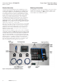
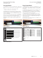
The PXMP Meter provides two Com ports with RS485 serial interfaces supporting Slave Modbus RTU protocol. Com 1 and Com 2
provide two RS-485 serial communication ports supporting Modbus
Slave RTU protocol.
The PXMP Configuration Software is a JAVA application provided
free of charge by Eaton to support the configuration and commissioning of the PXMP Meter. This utility is included on a CD provided
with each PXMP-MB. The software can also be downloaded from
the Eaton Power Xpert Multi-Point Meter Web site. Please refer to
the PXMP Configuration Software Manual MN150002EN for details.
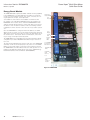
Both RS-485 Modbus slave ports can be addressed from 1 to 99
using two rotary switches on the face of the PXMP-MB assembly.
The Modbus slave ID selected with the rotary switches applies to
both Modbus Slave ports. The default communication settings are
115.2 K baud, no parity, one stop bit.
The PXMP Configuration Software can be used to adjust these
communication settings.
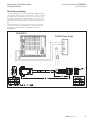
The slave port connectors include a Data+ (D+), Data- (D-), Common,
and Shield terminals. Eaton recommends the use of RS-485 wiring that includes a twisted pair for data, a conductor for common,
and a separate shield for optimal signal integrity and noise immunity. There are some variations on RS-485 wiring. If the PXMP-MB
assembly is to be inserted into a daisy-chain that does not have an
independent common and shield, the common and shield terminals
can be jumpered externally on the terminal block so that the RS485
common will connect via the shield between nodes.
For local configuration of a PXMP Meter, the software can be run
on a laptop computer equipped with JAVA 1.7 or higher. For instructions on the use of the PXMP Configuration Software Manual
MN150002EN.
To simplify PXMP configuration, a Wizard is provided that guides the
operator through a complete configuration process. The software
supports both online and offline configuration sessions. To conduct
an online session, connect the laptop to the USB port on the PXMPMB using a standard USB cable with a Type B USB connector to
interface with the meter. Start the software and it will automatically
connect to the PXMP Meter. Configuration can also be done over an
RS-485 Modbus communications link to either of the PXMP Meter’s
Com ports 1 or 2.
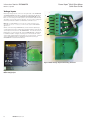
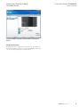
When launched, the PXMP Configuration Software presents the
User with a screen that allows the base information for the electrical
system to be entered.
After the base electrical system information has been entered, the
PXMP Configuration Software allows the User to enter the information for each slot in the PXMP-MB assembly.
In addition to device configuration, to verify correct device configuration and commissioning, the software can also be used in Monitor
Mode to view the metering data for each tenant meter.
Com Port 1
The PXMP Configuration Software is not intended for use as a
permanently installed software solution and does not provide cost
allocation functionality. Note also that the USB port is intended for
temporary configuration setup, commissioning, and debugging purposes only.
Com Port 2
Figure 27. Configuration Software Screen.
Figure 26. PXMP Communication Ports.
14
EATON www.eaton.com