1
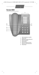
Information Booklet IB150001EN
Effective July 2013
Power Xpert® Multi-Point Meter
Quick Start Guide
Contents
DescriptionPage
Product Overview . . . . . . . . . . . . . . . . . . . . . . . . . 2
Ordering Information. . . . . . . . . . . . . . . . . . . . . . . 2
Material Selection Example. . . . . . . . . . . . . . . . . . 4
Meter Base . . . . . . . . . . . . . . . . . . . . . . . . . . . . . . 5
Meter Base - Assembly. . . . . . . . . . . . . . . . . . . . . 5
Voltage Inputs. . . . . . . . . . . . . . . . . . . . . . . . . . . . 6
Meter Modules . . . . . . . . . . . . . . . . . . . . . . . . . . . 7
Current Sensors . . . . . . . . . . . . . . . . . . . . . . . . . . 9
Sensor Orientation . . . . . . . . . . . . . . . . . . . . . . . . 9
Pulse Input Modules. . . . . . . . . . . . . . . . . . . . . . . 11
Digital Output Module. . . . . . . . . . . . . . . . . . . . . . 11
Energy Portal Module . . . . . . . . . . . . . . . . . . . . . 12
Touch Screen Display . . . . . . . . . . . . . . . . . . . . . 13
Communication Ports . . . . . . . . . . . . . . . . . . . . . 14
PXMP Configuration Software. . . . . . . . . . . . . . . 14
Information Booklet IB150001EN
Effective July 2013
Power Xpert® Multi-Point Meter
Quick Start Guide
Product Overview
Ordering Information
The Eaton Power Xpert® Multi-Point Meter (PXMP Meter) offers
a highly modular approach to high density metering applications in
electrical power distribution. The PXMP Meter is compatible with
most 3-phase industrial, commercial, and single-phase residential
low voltage electrical power systems. Typical applications include
feeder and branch circuit load monitoring found in switch and panel
boards, however higher level metering is possible with interposing load sensors and potential transformers. The modularity of
the PXMP Meter allows this metering system to be customized to
suit each metering installation based on the number and type of
circuits to be metered. Up to ten different PXMP Meter Modules
(PXMP-MMs) can be mixed and matched within a PXMP Meter Base
(PXMP-MB) to accommodate a total of up to 60 poles of metering
channels from a variety of 1, 2, 3 pole loads.
The PXMP Meter system offers the flexibility to be used in a variety
of applications and can be customized, using the modular components, to fit most installations. Table 1 lists the modular components available for the PXMP Meter system.
Various meter modules can be mixed and matched in a single PXMP
Meter Base with support for split core sensors, solid core sensors,
or both based on the circuits that need to be metered. In addition,
PXMP Pulse Input Modules (PXMP-PIMs) can be installed into a
PXMP Meter base for pulse metering from other electricity, gas,
water, air, or steam meters.
Output modules are available for either remote control over Modbus
or automatic control by the PXMP Meter based on customer configured threshold triggers. A PXMP Energy Portal Module (PXMP-EPM)
is available that can make metered data available to individual tenants via an embedded WEB server. The Energy Portal module also
supports a variety of protocols including Modbus TCP, SMTP, SNMP,
FTP, HTTP, and more. In addition to Ethernet, the Energy Portal
Module supports an optional dial up telephone connection for interface with remote billing software. A Touch Screen Display is available for local display of metered data from any circuit.
Figure 1. Components of the PXMP Meter System.
2
EATON www.eaton.com
Power Xpert® Multi-Point Meter
Quick Start Guide
Information Booklet IB150001EN
Effective July 2013
Table 1. PXMP Meter System – Modular Components.
Catalog Number
Description
PXMP-MB Meter Bases
PXMP-MB*
PXMP Meter Base - 3PH/1PH 2W w/ ABCN Voltage Inputs
PXMP-MB-AB**
PXMP Meter Base - 1PH 3W w/ ABN Voltage Inputs
Catalog Number
Description
CSXXX - Current Sensors with 10 mA Max.
Outputs
CS050
Current Sensor Module 50 Amps (10 mA output) - Kit x 6
CS125
Current Sensor Module 125 Amps (10 mA output) - Kit x 3
CS200
Current Sensor Module 200 Amps (10 mA output) - Kit x 3
CS400
Current Sensor Module 400 Amps (10 mA output) - Kit x 3
CS005
Current Sensor Module 5 Amps (10 mA output)
(For use with 5 Amp CTs) - Kit x 3
Sensor Cables for PXMP-CSXXX and PXMPIMXXX
PXMP-SC4-3
PXMP Sensor Cable, 4 Ft. (1.22 m) - (male/male) Kit x 3
PXMP-SC6-3
PXMP Sensor Cable, 6 Ft. (1.8 m) - (male/male) Kit x 3
PXMP-SC8-3
PXMP Sensor Cable, 8 Ft. (2.44 m) - (male/male) Kit x 3
PXMP-SC12-3
PXMP Sensor Cable, 12 Ft. (3.66 m) - (male/male)Kit x 3
PXMP-MMXXXXX Meter Modules
PXMP-MM10MA
PXMP Meter Module w/ 6 10 mA Inputs
PXMP-MM100MA
PXMP Meter Module w/ 6 100 mA Inputs
PXMP-MM333MV
PXMP Meter Module w/ 6 333 mV Inputs
PXMP-MM10MA-AB
PXMP Meter Module w/ 6 10 mA Inputs - 1 PH 3W
PXMP-MM100MA-AB PXMP Meter Module w/ 6 100 mA Inputs - 1 PH 3W
PXMP-MM333MV-AB PXMP Meter Module w/ 6 333 mV Inputs - 1 PH 3W
PXMP-PIM
PXMP Meter Pulse Input Module w/ 8 Inputs
Sensor Cable Extensions
PXMP-DOM
PXMP Meter Digital Output Module w/ 8 Outputs
PXMP-EPM Energy Portal Modules
PXMP-EPM
PXMP Meter Energy Portal Module
PXMP-EPM-M
PXMP Meter Energy Portal Module w/ Modem
PXMP-CSXXX Current Sensors with 100 mA
Max. Outputs
PXMP-CS125-3
PXMP CS125 Sensor (100 mA output) - Kit x 3
PXMP-CS250-3
PXMP CS250 Sensor (100 mA output) - Kit x 3
PXMP-CS400-3
PXMP CS400 Sensor (100 mA output) - Kit x 3
* = PXMP-MB only supports PXMP-MM10MA-AB,
PXMP-MM100MA-AB, and PXMP-MM333MV-AB.
** = PXMP-MB-AB only supports PXMP-xxxxxxx-AB modules.
PXMP-SCE8-3
PXMP Sensor Extension Cable, 8 Ft. (2.44 m) - (male/female)
Kit x 3
PXMP-SCE16-3
PXMP Sensor Extension Cable,16 Ft. (4.88 m) - (male/female)
Kit x 3
(Current Sensor) Interface Modules
PXMP-IM333MV-3
PXMP Current Sensor Interface Module (for 333 mV) -Kit x 3
PXMP-DISP Display
PXMP-DISP-6
Eaton HMIVU06CUNB1 6-inch Color Touch-Screen Interface,
Preloaded and Optimized for Use with the PXMP
24 Vdc Power Supplies
PSG60E
Power Supply 100-240 Vac Input, 24 Vdc 60 W Output
- See Eaton PSG Power Supply Family for More Details
- Input Voltage Ranges and Load Requirements Will Vary Per
Application
PSG120E
5 Amp (120 W)
PSG240E
10 Amp (240 W)
PSG480E
20 Amp (480 W)
PSG60F
3-phase Power Supply 320-575 Vac L:L Input, 24 Vdc 60 W
Output
- See Eaton PSG Power Supply Family for More Details
- Input Voltage Ranges and Load Requirements Will Vary Per
Application
PSG120F
5 Amp (120 W)
PSG240F
10 Amp (240 W)
PSG480F
20 Amp (480 W)
EATON www.eaton.com
3
Power Xpert® Multi-Point Meter
Quick Start Guide
Information Booklet IB150001EN
Effective July 2013
Material Selection – Example
The application below (details described in upper left section of the
drawing) is to monitor various 3-phase and single-phase breakers in
an Eaton IFS Switchboard (see Figure 2). The required PXMP hardware layout is shown and the required modules per slot are listed on
this drawing. Individual selection steps are listed at the bottom of
the page.
A
B
C
D
E
F
G
H
I
J
1
1
Power Xpert MultiPoint Meter
480Y/277V IFS. Monitored Circuits;
3 – 400 amp, 3 Phase Breakers
6 – 125 amp, 1 Phase Breakers
8 – 30 amp, 1 Phase Breakers
4 - Pulse Inputs (Pulse Counters)
3 – Digital Outputs (Alarms)
Monitoring Web-Views, Modbus TCP, Color Display.
2
Bill of Material required;
QTY - Description
1 – PMXP-MB (Meter Base)
3 – PXMP-MM100MA (100ma Modules)
2 – PXMP-MM10MA (10ma Modules)
1 – PXMP-MM333MV (333mv Module)
1 – PXMP-PIM (Pulse Input Module)
1 – PXMP-DOM (Digital Output Module)
1 – PXMP-DISP-6 (6” color local Display)
1 – PXG60E (Din rail Power Supply)
3 – PXMP-CS400-3 (Current Sensor Kits)
2 – PXMP-CS125-3 (Current Sensor Kits)
2 – CS050 (Current Sensor Kits)
3
4
5
Color Display
w/ 4 ft. cable
Current Sensor Kit
4
333mV Meter Modules
Digital Output Module
Meter Base
Pulse Input Module
10ma Meter Modules
Power Supply
100ma Meter Modules
DFTR
B
Notes:
REVISION
For Submittal
2. Meter Modules and Meter base must match (both must be 3ph/1ph design).
3.100ma Meter Modules must connect to 100Ma Current Sensors.10mA Meter Module to CSXXX 10mA Current Sensor
March, , 2013
B
C
D
DATE
5
6
THE INFORMATION ON THIS DRAWING IS THE PROPERTY OF
EATON CORPORATION. IT IS DISCLOSED IN CONFIDENCE
AND IS NOT TO BE REPRODUCED, USED OR DISCLOSED
EXCEPT FOR THE PURPOSE FOR WHICH FURNISHED.
Eaton Corporation
APPD
DATE
ENG. REF.
DATE TITLE
NEXT REF.
DATE
Power Xpert MultiPoint Meter
Hardware Example #1
SHEET NO
4. Sensor Cables, based upon length required, ordered separately.
A
DATE
DJW
APPD
1. Must use Meter base designed for both three phase and single phase circuits.
8
3
Slot 1 – One PXMP-MM100MA for two 3ph Breakers, use two PXMP-CS400-3 Current Sensor Kits. (Monitors 2 – 400A Breakers)
Slot 2 = One PXMP-MM100MA for one 3ph Breaker use one PXMP-CS400-3 Current Sensor Kits. (Monitors 1 – 400A Breakers with three pole future.)
Slot 3 – One PXMP-MM100MA for six 1ph Breakers, use two PXMP-CS125-3 Current Sensor Kit. (Monitors 6 - 125A Breakers)
Slot 4 – One PXMP-MM10MA for six 1ph Breakers, use one CS050 Current Sensor Kits. (Monitors 6 - 30A Breakers)
Slot 5 – One PXMP-MM10MA for six 1ph Breakers, use one CS050 Current Sensor Kit. (Monitors 2 – 30A Breaker with four one pole future)
Slot 7 – One PXMP-PIM for up to 8 Pulse Inputs.
Slot 8 – One PXMP-DOM for up to 8 Digital Outputs. Alarm Outputs created using PXMP Configuration Software
Slot 9 – Future Slot
Slot 10 – Energy Portal Module must always be installed in slot 10 (Includes Modbus TCP and Web-Views)
6
7
2
1 OF 1
E
SIZE
A
SCALE
NONE
ORDER REF.
GO# XXXXXXX
DWG NO
REV 1.0
F
Figure 2. Example PXMP Meter Configuration.
Step 1. Select the PXMP-MB; 3-phase and single-phase monitoring required - Use PXMP-MB Base.
Step 5. Select the Modbus TCP - use PXMP-EPM (Ethernet
Comms and Web-Views).
Step 2. Select the PXMP Meter Modules (PXMP-MMs). Match
3-phase/single-phase modules to (3-phase/singlephase) PXMP-MP meter base.
Step 6. Select the sensor cable extensions - add PXMP-SCx-3
cables between PXMP-MMs and current sensors as
needed.
NNote: Modules can be either 100 mA, 10 mA and or 333 mV rated.
Step 3. Select the number of PXMP-MMs; two 3-phase per
module or six single-phase per module.
Step 4. Select the current sensor type; (match current sensors
to PXMP-MMs).
NNote: Use 100 mA CS w/ 100 mA module, 10 mA CS w/ 10 mA module, 333
mV CS w/ 333 mV module.
4
EATON www.eaton.com
NNote: CSxxx sensors include 48” (1.22 m) cables. 333 mV sensors require an
interface module.
Step 8. Select the local display - use PXMP-DISP-6 (provided
with a 48” (1.22 m) cable, connects to PXMP-MB port.
Step 9. Select the power supply - use PXG60E (Din rail mount
120 to 24 Vdc).
Power Xpert® Multi-Point Meter
Quick Start Guide
Information Booklet IB150001EN
Effective July 2013
Meter Base
Meter Base Assembly
Both PXMP Meter Base assembly models are shipped without modules. The front of the base has a label indicating 10 positions or slots
(1-10), where modules can be mounted. Each position is covered
with a metal slot cover secured to the assembly with screws. The
slot covers protect the backplane of the PXMP-MB assembly. Slot
covers are removed to insert modules, but should be left in place if
the slot is not being used. The ten slots provided are multi-purpose.
They can accommodate any combination of PXMP-MMs (10 mA, 100
mA, or 333 mV), PXMP-PIMs, or PXMP-DOM.
The PXMP-MB assembly includes a solid-state relay output that can
be configured as a Pulse Initiator output assigned to any one of the
tenant meters or to the aggregate sum of the tenant meters. An
external 24 Vdc power supply is required to drive the load limited
to 80 mA maximum. The PXMP-MB assembly also includes three
digital status inputs that can be used to indicate conditions such as
a demand synch pulse or a rate alert. These digital inputs require
external 24 Vdc voltage +/- 20% to operate.
NNote: The PXMP-MB (3-phase 4-Wire Wye, 3-phase 3-Wire Delta (grounded),
and single-phase Metering) can be used on 3-phase, 2-phase, and singlephase applications. The PXMP-MB-AB (120/240 V, single-phase 3-Wire service) can ONLY be used on single-phase applications. The PXMP-MB-AB base
has a yellow label on the lower left of base (see Figures 3 and 4).
The Mode DIP switches are located behind the metal door cover at
the top left corner of the black label face of the PXMP-MB assembly
panel. These Mode switches are used to secure the PXMP Meter in
one of three levels of hardware enforced security modes. Note the
tab off the base that can be used to seal the door shut for security
purposes.
Figure 3. PXMP-MB (White Label).
Figure 5. PXMP-MB Assembly Components and LEDs.
The PXMP-MB assembly includes the following LED indicators:
•
Three LEDs marked A, B, and C, adjacent to the Meter Voltage
Input connector, indicate if voltage is applied to the meter phase
inputs and is within the expected range.
•
Two LED’s are marked Delta or Wye/1PH and used to indicate the
active metering mode configuration.
•
Red and green TX and RX LED’s adjacent to Com 1 and Com 2
provide visual indication of Transmit and Receive activity on the
communication ports.
•
A Health LED indicates that the PXMP-MB main microprocessor
is functioning correctly.
•
A Power LED indicates that 24 Vdc is applied to the 24 Vdc input
to the PXMP-MB.
•
A Status LED indicates that communication activity between the
PXMP-MB and PXMP-MMs.
Figure 4. PXMP-MB-AB (Yellow Label - Shown with Three
Modules Installed).
EATON www.eaton.com
5
Power Xpert® Multi-Point Meter
Quick Start Guide
Information Booklet IB150001EN
Effective July 2013
Voltage Inputs
Metering voltage inputs connect to the right side of the PXMP-MB
and PXMP-MB-AB assemblies. Inputs are marked A (V1), B (V2), C
(V3), and N (VR) on both the PXMP-MB and PXMP-MB-AB assemblies. If connecting to a Delta system, the unused N (VR) terminal
should be connected to chassis ground. A cover for the voltage terminal is provided as a barrier to hazardous terminal access.
N
C
NNote: On the PXMP-MB-AB, even though the voltage input label on the
assembly lists the “C” connection, it will never be used in PXMP-MB-AB
applications.
When commissioning a PXMP Meter, ensure that the phasing is
consistent between the voltage input terminal and the load current
sensor input connections on the PXMP-MMs. If a current sensor is
plugged into a connection point on the PXMP-MM that is assigned
to a different phase voltage, metering errors will result due to the
current and voltage phasing mismatch (see Sections 4.3.4 - Current
Sensor Installation and 6 - Configuring and Commissioning of
IM150001EN for detailed information).
B
A
"N" Connections
"C" Connections
"B" Connections
"A" Connections
Figure 6. A, B, C, and N Connections on the PXMP-MB Assembly
Meter Voltage Input.
6
EATON www.eaton.com
Figure 7. Meter Voltage Input Terminal Plug and Cover.
Power Xpert® Multi-Point Meter
Quick Start Guide
Information Booklet IB150001EN
Effective July 2013
Meter Modules
Each PXMP-MM has six 2 x 2 female receptacles for current sensor
connections. Each 2 x 2 receptacle can be considered to be in one
of six rows of connection points for the PXMP-MMs that are normally installed in slots one through nine. Each horizontal row is paired
with the phase voltage indicated on the phase assignment label
to the left. For the PXMP-MB assembly, the bottom row of three
connectors is always Phase A, the second row from the bottom is
always Phase B, and the third row from the bottom is always Phase
C . The same applies to the upper set of three connectors. Note the
PXMP-MB CT inputs label is WHITE and the PXMP-MB-AB CT Inputs
label is YELLOW to help distinguish between these two PXMP-MB
designs. For the PXMP-MB-AB assembly, the bottom row is always
Phase A1, then working upwards Phase B1, Phase A2, Phase B2,
Phase A3, and Phase B3 at the top.
Pulse Output LEDs
Health and Com LEDs
Meter Module Current Sensor
Compatibility Marking
Current Sensor Input
Connections
Load Power +/- LEDs
Figure 9. Typical PXMP-MM.
White
Meter &
Channel
Labeling
(White Meter
Label Must
Match White
Meter Module
Channel
Labeling)
Figure 8. PXMP-MB Examples.
Yellow
Meter &
Channel
Labeling
(Yellow Meter
Label Must
Match Yellow
Meter Module
Channel
Labeling)
Figure 10. .PXMP-MB-AB Examples.
EATON www.eaton.com
7
Power Xpert® Multi-Point Meter
Quick Start Guide
Information Booklet IB150001EN
Effective July 2013
Va Vb Vc Vn
A
A
A
A
B
B
B
B
C
C
C
C
C2
B2
A2
C1
B1
A1
C2
B2
A2
C1
B1
A1
EATON www.eaton.com
N
C
B
A
Load #3
N
C
B
A
Load #2
N
C
B
A
Load #1
Phase A Sensors Connect to A1 or A2
Phase B Sensors to Connect B1 or B2
Phase C Sensors to Connect C1 or C2
100-240 VAC
50-60 Hz
125-250 VDC
8
Load #4
Sensor Type and Phasing must match
Meter Module!
100mA Sensors to 100 mA Meter Module
10mA Sensors to 10 mA Meter Module
333mV Sensors to 333 mV Meter Module
Figure 11. Typical Wiring – 3-Phase 4-Wire Wye.
Figure 12. Typical Wiring – Single-Phase 3-Wire 120/240.
N
C
B
A
Power Xpert® Multi-Point Meter
Quick Start Guide
Information Booklet IB150001EN
Effective July 2013
Current Sensors
Sensor Orientation
Three different types of current sensors can be used with the PXMP
Meter based on secondary output type and range. The PXMP Meter
is compatible with direct connection to 100 mA, 10 mA, and 333
mV maximum rated secondary current sensors. All single CT applications require that the CT provides Double/Reinforced Insulation
600V, CATIII. By using interposing current transformers such as
the CS005, current transformers with 1 or 5 Amp outputs can be
interfaced. Each current sensor is slightly different. Some require
special mounting.
The orientation of the sensor relative to the load current flow is
important for proper metering. Current sensing is directional.
Sensors should be mounted on the insulated load cables facing the
load current back to front as shown by the arrow on top of the sensor or similar direction marking. An incorrect orientation results in
an incorrect energy reading.
The PXMP-MMs are directly compatible with Eaton’s CSXXX 10 mA
and PXMP-CSXXX 100 mA current sensors. The CSXXX current
sensors have an integral yellow 4 ft (1.22 m) cable while the PXMPCSXXX current sensors require a separate PXMP-SC sensor cable
that is in available 4/6/8/12 ft. (1.22/1.83/2.44/3.66 m) lengths to help
cleanly match the application dimensions. Generic 333 mV output
current sensors must use the PXMP-IM333MV Interface Modules
and a PXMP-SC Sensor Cable to interface with a PXMP-MM. In
a PXMP Meter System, the CSXXX 10 mA secondary output sensors should be connected only to a PXMP-MM10MA 10 mA Meter
Module. The 10 mA sensor cables are yellow in color, ~ 48 in. (1.22
m) long and are built integral with the sensor. Eight and 12 ft. (2.44
and 3.66 m) extensions are available to extend the distance between
the sensor and the Meter. Do not exceed 28 ft (8.53 m) total length.
Two LED indicators per load circuit on the PXMP-MM will indicate
the power polarity. Note that the green LED on the PXMP-MM indicates current flow towards the load. The red LED indicates current
is flowing from the load towards the source. Normally, a red LED
indicates that the sensor is mounted backwards. The red LED would
be correct if the circuit being monitored is a generator not a load. If
there is not adequate current flow, the sensor cable is disconnected
or the PXMP-MB assembly is powered down, or if the meter voltage
inputs are disconnected then these indicators will be off.
Meter Modules
Breaker
Sensors
Sensor
Cables
Figure 13. PXMP-CSXXX Current Sensor - 100 mA.
Figure 16. Typical Wiring Arrangement of Sensor Connected to
Meter Module.
To Sourcing Breaker
Figure 14. PXMP Current Sensor Cable.
Yellow Secondary Cable
Figure 17. CS050/125/200/400 Current Sensors – Load
Orientation.
Figure 15. 10 mA CS125 Solid Core Current Sensor with Integral
48 in. (1.22 m) Cable.
EATON www.eaton.com
9
Power Xpert® Multi-Point Meter
Quick Start Guide
Information Booklet IB150001EN
Effective July 2013
Va Vb Vc Vn
A
A
A
A
B
B
B
B
C
C
C
C
C2
B2
A2
C1
B1
A1
C2
B2
A2
C1
B1
A1
N
C
B
A
Load #4
N
C
B
A
Load #3
N
C
B
A
Load #2
N
C
B
A
Load #1
Sensor Type and Phasing must match
Meter Module!
100mA Sensors to 100 mA Meter Module
10mA Sensors to 10 mA Meter Module
333mV Sensors to 333 mV Meter Module
Phase A Sensors Connect to A1 or A2
Phase B Sensors to Connect B1 or B2
Phase C Sensors to Connect C1 or C2
Figure 18. 3-Phase 4-Wire Service Using Two 3-Phase Current Sensors.
Va Vb Vc Vn
A
C
B
A
C
B
A
C
B
A
C2
B2
A2
C1
B1
A1
EATON www.eaton.com
Load #10
N
C
Load #9
N
B
Load #8
N
A
Load #7
N
C
Load #6
N
B
Load #5
N
A
Load #4
N
C
Load #3
N
B
Load #2
N
A
Load #1
Sensor Type and Phasing must match
Meter Module!
100mA Sensors to 100 mA Meter Module
10mA Sensors to 10 mA Meter Module
333mV Sensors to 333 mV Meter Module
A2
C1
B1
A1
Figure 19. 3-Phase 4-Wire Service Using Ten Single-Phase, 1 Pole Current Sensors.
10
N
A
Phase A Sensors Connect to A1 or A2
Phase B Sensors to Connect B1 or B2
Phase C Sensors to Connect C1 or C2
Power Xpert® Multi-Point Meter
Quick Start Guide
Information Booklet IB150001EN
Effective July 2013
Pulse Input Module
Digital Output Module
The PXMP-PIM has terminals for eight digital inputs. Eight front facing LEDs on the Pulse Input Module flash when digital inputs transition.
The PXMP-DOM provides outputs from the PXMP-MB logic to external circuit groups. These outputs are used for control or to indicate
alarm conditions. A typical installation might be for building automation systems.
•
LED On = Contact closed, current flowing into input;
•
LED Off = Contact open; no current flowing;
The PXMP-PIM has a 2-position, 24 V power supply terminal that
must be connected to an external 24 Vdc power supply. The same
24 V power supply that is used for the PXMP-MB assembly can be
used for the PXMP-PIMs.
Input of the source pulse must be a dry contact. Each PXMP-PIM
has a 2.2 K ohm input impedance drawing approximately 10 mA per
closed input. All the commons are tied together internally.
Metering of ten, 3-phase tenants, for example, would require five
PXMP-MMs to meter ten, 3-phase loads (two tenants per meter
module).
P ul s e I n
Module
The PXMP-DOM can be controlled remotely over Modbus, or driven
by logic from the PXMP-MB, based on customer configuration.
The PXMP-DOM requires an external power source of 24 Vdc +/20% V. Each solid state relay can support a maximum load of 80
mA. Each Solid state relay circuit is electrically
The PXMP-DOM plugs into the PXMP-MB with captive screws.
These screws, when tightened, ground the module to the PXMPMB and to the earth ground. The PXMP-DOM has eight front-facing
LEDs to display the status of each output. Other LEDs indicate
COM Status and Health.
External 24 Vdc source should be dedicated for local PXMP use only,
do not connect to a CAT III source.
C om
H e a lth
PI1
PI2
PI3
PI4
PI5
PI6
PI7
PI8
Figure 22. PXMP-DOM.
Figure 20. PXMP-PIM.
24Vdc
2.2 K Ohm Input Impedance w/Internal Common Connection
PI1
1
Common
2
Pulse Meter 1 Form A Contact - Dry
PI3
Pulse Meter 2 Form A Contact - Dry
PI4
Pulse Meter 4 Form A Contact - Dry
PI5
Pulse Meter 5 Form A Contact - Dry
PI6
Pulse Meter 6 Form A Contact - Dry
PI7
Pulse Meter 7 Form A Contact - Dry
4
PI2
3
Pulse Meter 3 Form A Contact - Dry
5
6
7
8
9
10
11 12
13 14
15 16
PI8
-
24V
+
Figure 21. PXMP-PIM Wiring.
Pulse Meter 8 Form A Contact - Dry
24V (+)
24V (-)
Pulse Input Module Power
Figure 23. PXMP-DOM Wiring.
EATON www.eaton.com
11
Power Xpert® Multi-Point Meter
Quick Start Guide
Information Booklet IB150001EN
Effective July 2013
Energy Portal Module
The PXMP-EPM adds sophisticated Web enabled metering capability
to the PXMP Meter. A typical application would be for storing the
results of metering utilities (electric, gas, water, or steam), for serving an apartment complex, tenant by tenant.
Stored data for each tenant is then available over Ethernet with
the support of an embedded JAVA Applet that is pre-loaded in the
PXMP-EPM. This module can be ordered as PXMP-EPM-M which
supports internal dial up telephone modem with RJ11 connection at
the bottom of the module for interface with remote billing software
in applications where network connections are not possible or practical.
Once the PXMP-EPM is configured with an IP address, the JAVA
Applet can be accessed over a Local Area Network (LAN). Metering
data can be viewed for each tenant, as well as an aggregated sum of
the tenant meters. This feature allows for E-Allocation, or the limiting of energy consumption tenant by tenant.
The PXMP-EPM comes standard with a front facing Ethernet RJ-45
configuration port and a LAN/WAN RJ-45 Ethernet jack on the bottom end.
The Energy Portal Module plugs into the tenth slot of the PXMP-MB
assembly. It will not function properly in any other slot. The PXMPEPM is secured with captive screws that, when tightened, ground
the PXMP-EPM to the Meter Base and to the earth ground. For configuration and application details please refer to the “PXMP Energy
Portal Web Interface and User Manual” (MN150003EN).
Health and
Status LEDs
Com
Reset
Com Port 1
Local
Display
IP Add.
LED
Modem
Option
LEDs
Local
Configuration
RJ45 Ethernet
LAN/WAN
LEDs
LAN/WAN
RJ45
Ethernet
Port
Optional
RJ11
Telephone
Modem
.
12
EATON www.eaton.com
Figure 24. PXMP-EPM.
Com Port 2
Power Xpert® Multi-Point Meter
Quick Start Guide
Information Booklet IB150001EN
Effective July 2013
Touch Screen Display
The Eaton PXMP-DISP-6, is an Eaton HMIVU06CUNB1 preloaded
with software optimized and a 4 ft (1.22 m) Com. cable for use with
the PXMP Meter and installing it on the enclosure with the meter.
The display provides the User with the ability to locally view meter
readings to help troubleshoot problems that may arise, and view
power system metering data when a computer is not handy or available.
The optional display is for system monitoring purposes only and
cannot be used to set-up the PXMP Meter. Set-up of the meter
must be done using the PXMP Configuration Software (see
MN150002EN).
PXMP-DISP-6
Figure 25. PXMP Touch Screen Display and Wiring Information.
EATON www.eaton.com
13
Power Xpert® Multi-Point Meter
Quick Start Guide
Information Booklet IB150001EN
Effective July 2013
Communication Ports
PXMP Configuration Software
The PXMP Meter provides two Com ports with RS485 serial interfaces supporting Slave Modbus RTU protocol. Com 1 and Com 2
provide two RS-485 serial communication ports supporting Modbus
Slave RTU protocol.
The PXMP Configuration Software is a JAVA application provided
free of charge by Eaton to support the configuration and commissioning of the PXMP Meter. This utility is included on a CD provided
with each PXMP-MB. The software can also be downloaded from
the Eaton Power Xpert Multi-Point Meter Web site. Please refer to
the PXMP Configuration Software Manual MN150002EN for details.
Both RS-485 Modbus slave ports can be addressed from 1 to 99
using two rotary switches on the face of the PXMP-MB assembly.
The Modbus slave ID selected with the rotary switches applies to
both Modbus Slave ports. The default communication settings are
115.2 K baud, no parity, one stop bit.
The PXMP Configuration Software can be used to adjust these
communication settings.
The slave port connectors include a Data+ (D+), Data- (D-), Common,
and Shield terminals. Eaton recommends the use of RS-485 wiring that includes a twisted pair for data, a conductor for common,
and a separate shield for optimal signal integrity and noise immunity. There are some variations on RS-485 wiring. If the PXMP-MB
assembly is to be inserted into a daisy-chain that does not have an
independent common and shield, the common and shield terminals
can be jumpered externally on the terminal block so that the RS485
common will connect via the shield between nodes.
For local configuration of a PXMP Meter, the software can be run
on a laptop computer equipped with JAVA 1.7 or higher. For instructions on the use of the PXMP Configuration Software Manual
MN150002EN.
To simplify PXMP configuration, a Wizard is provided that guides the
operator through a complete configuration process. The software
supports both online and offline configuration sessions. To conduct
an online session, connect the laptop to the USB port on the PXMPMB using a standard USB cable with a Type B USB connector to
interface with the meter. Start the software and it will automatically
connect to the PXMP Meter. Configuration can also be done over an
RS-485 Modbus communications link to either of the PXMP Meter’s
Com ports 1 or 2.
When launched, the PXMP Configuration Software presents the
User with a screen that allows the base information for the electrical
system to be entered.
After the base electrical system information has been entered, the
PXMP Configuration Software allows the User to enter the information for each slot in the PXMP-MB assembly.
In addition to device configuration, to verify correct device configuration and commissioning, the software can also be used in Monitor
Mode to view the metering data for each tenant meter.
Com Port 1
The PXMP Configuration Software is not intended for use as a
permanently installed software solution and does not provide cost
allocation functionality. Note also that the USB port is intended for
temporary configuration setup, commissioning, and debugging purposes only.
Com Port 2
Figure 27. Configuration Software Screen.
Figure 26. PXMP Communication Ports.
14
EATON www.eaton.com
Power Xpert® Multi-Point Meter
Quick Start Guide
Information Booklet IB150001EN
Effective July 2013
Figure 28. PXMP Configuration Software Meter Configuration
Screen.
Additional Information
Detailed information on applications and options can be found in the
Power Xpert Multi-Point Meter User Guide (IM150001EN). The guide
can also be found at http://eaton.com/powerxpert.
EATON www.eaton.com
15
Information Booklet IB150001EN
Effective July 2013
Power Xpert® Multi-Point Meter
Quick Start Guide
This Information Booklet is published solely for information purposes
and should not be considered all-inclusive. If further information is
required, you should consult an authorized Eaton sales representative.
The sale of the product shown in this literature is subject to the
terms and conditions outlined in appropriate Eaton selling policies
or other contractual agreement between the parties. This literature
is not intended to and does not enlarge or add to any such contract.
The sole source governing the rights and remedies of any purchaser
of this equipment is the contract between the purchaser and Eaton.
NO WARRANTIES, EXPRESSED OR IMPLIED, INCLUDING
WARRANTIES OF FITNESS FOR A PARTICULAR PURPOSE OR
MERCHANTABILITY, OR WARRANTIES ARISING FROM COURSE
OF DEALING OR USAGE OF TRADE, ARE MADE REGARDING
THE INFORMATION, RECOMMENDATIONS, AND DESCRIPTIONS
CONTAINED HEREIN. In no event will Eaton be responsible to the
purchaser or user in contract, in tort (including negligence), strict
liability or otherwise for any special, indirect, incidental or consequential damage or loss whatsoever, including but not limited to
damage or loss of use of equipment, plant or power system, cost
of capital, loss of power, additional expenses in the use of existing
power facilities, or claims against the purchaser or user by its customers resulting from the use of the information, recommendations
and description contained herein.
Eaton
Electrical Sector
1000 Eaton Boulevard
Cleveland, OH 44122
United States
877-ETN-CARE (877-386-2273)
Eaton.com
© 2013 Eaton
All Rights Reserved
Printed in USA
Publication No. IB150001EN / TBG001089
July 2013
Eaton is a registered trademark.
All other trademarks are property of their
respective owners.