1
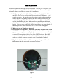
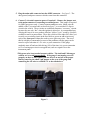
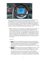
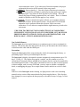
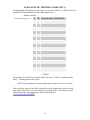
FOR ISO VEHICLES by USER MANUAL FIRMWARE VERSION 4.1 for Audi/VW ISO www.aeroforcetech.com Made in the USA! Patent Pending WARNING Vehicle operator should focus primary attention to the road while using the Interceptor. The information provided by this device should be observed as part of a normal sequence of observations performed in the operation of the vehicle, as with any gauge or other instrumentation. Interceptor settings should be changed only during conditions when it is safe to do so. Focusing on the road should be the primary concern of the driver. Aeroforce Technology Inc. shall not be held liable in any way for any incidental or consequential damages to the vehicle, driver, passengers, and or other involved parties or property occurring while using the Interceptor scan gauge. Aeroforce Technology Inc. shall not be liable for technical or editorial errors or omissions made herein, nor for incidental or consequential damages resulting from the furnishing or use of this manual. Aeroforce Technology Inc. reserves the right to make changes to this document and the product described without notice. Copyright 2005-2013 Aeroforce Technology, Inc. All rights reserved. 2 INSTALLATION Read these instructions thoroughly before installation. Also, be sure to check for your vehicle specific notes in appendix A at the end of this manual. There could be important information there concerning your gauge and its installation. 1. Configure gauge bezel and face if desired. Unscrew bezel and lift off the lens and face. Once the face and lens is off, do not touch the LCD display. It will scratch very easily. The lens has a scratch resistant coating on the outer facing surface. When re-assembling make sure this outer surface remains facing the outside of the gauge. The other side of this lens can easily be scratched. Be careful when handling this lens. In the retail box you will find an additional white face. Re-assemble the gauge using any combination of faces or optional bezels. When screwing on the bezel, do this carefully as to not cross thread it. If threaded properly it should turn about 2 to 2 ½ times before being tight. 2. Make sure the car’s ignition is turned off. 3. Run included 5’, or optional 9’ main cable, and three wire mini cable, from the OBD2 connector (do not plug in yet) to the location of the Interceptor(s). The Interceptor will fit in any 2 1/16” or 52mm gauge pod, or can be mounted in a custom fashion anywhere within 5 feet of the OBD2 connector. The OBD2 connector is located under the dash on either side of the steering column. 9.5’ cables are available from our accessories page if extra length is needed. 4. Plug both cables into the back of the Interceptor. See figure 1. Press the Interceptor(s) into the gauge pod or mounting hardware. Figure 1 3 5. Plug the main cable connector into the OBD2 connector. See figure 2. The data, ground, and power on most vehicles come from this connector. 6. Connect 3 wire mini connector power if required*. Remove the jumper next to the main connector if connecting to external power. This jumper is required for OBD2 port power only. Connect separate red power wire, which exits the middle of the 3 wire mini cable as shown in figure 1, to a switched 12v line or circuit in the vehicle. These circuits are commonly known as “accessory” circuits because they are only “hot” when the ignition is turned on. A recommended way of doing this step is to use a product called an “Add a Circuit”, made by Littelfuse, available at most car parts outlets. These kits, which sell for under $10, allow you to easily use an existing circuit in the fuse block to power an add-on accessory such as the Interceptor without the need to cut or splice any wires. The use of this kit is highly recommended, as most of the problems with the gauge can be traced to a poor selection of a 12v wire, or poor connection. If the gauge randomly turns off and on while driving, 90% of the time it is a poor connection to 12v or an improper circuit was tapped into, such as a signal wire to the instrument panel. *This power wire is not needed on most vehicles. The Audi and Volkswagon vehicles we’ve tested have needed it. If the gauge is not turning on or off properly on these or any vehicle, you can force it on and off at the proper time by removing the small 2-pin jumper on the rear of the gauge and connecting the red wire to switched 12v as described above. Figure 2 4 6. Connect the 0-5v analog inputs (optional). You will see 3 pins above the main connector on the back of the gauge as shown in figure 1. The 2 outer pins connect to the analog inputs. The center pin is for switched 12v power as described above and may not be required. The right side pin, when looking at the rear of the gauge, goes to analog input 1. The left pin is for analog input 2. See figure 1. Included in the gauge packaging is a 3 wire cable that connects here. Once attached to the gauge, you’ll see that the green wire is for analog 1, the white for analog 2. These inputs can be used to read the outputs from pressure senders, A/F ratio analog outputs, 2 or 3 bar MAP sensors, or any voltage up to 5v that you want to monitor and/or record. You can scale these signals with a menu function described below. These inputs are rated for 0-5 volts, with an over-voltage protection circuit built in. However, running more than 6v into these inputs for an extended period of time could effect the operation of the entire gauge, and possible damage it. 7. Turn vehicle on. With the key on and engine off, or engine running, the Interceptor will power up. While the unit powers up, the “Interceptor” and “AeroForce” logo will appear on the display. This only takes a few seconds. Please note that dual Interceptor units may power up sequentially (one at a time) and may take up to 15 seconds. When turned on for the first time the Interceptor will ask you to enter a list of parameters that will then be available for scan, see “Setup” below in the Operation section for more details on this. See page A1 of these instructions for the list of parameters supported by the Interceptor. Remember that not all parameters are supported by every vehicle, so don’t expect to be able to view them all on the Interceptor you install in your vehicle. If the vehicle and the Interceptor support the parameter, you will have access to it. Dual units on vehicles that are powered by the OBD2 port may not power up at exactly the same time. OPERATION 1. SCANNING. Once the Interceptor has been installed and set up as described below, you will see an upper and lower field containing a description and parameter value when the ignition is turned on. The right button will change the upper parameter field, the left button the lower. One quick push of the button will toggle to the next parameter. Included in the list of parameters is instantaneous fuel economy, calculated horsepower, and both the analog 1 and analog 2 inputs. Fuel economy and horsepower will be available on only those cars using a Mass Air Flow sensor or a calculated air flow. Pressing and holding either button will result in the parameters to scroll for that associated field. While in normal scan mode, regardless of what parameters are being displayed, press and hold both buttons for 4 seconds or more. This will bring up the boost graph as shown below: 5 On the top left will be the actual boost level, top right the commanded boost value. On the graph, the filled in line will be actual boost, the simple line will be commanded boost. As time transpires, the graph will slowly move to left then off the screen as fresh data is plotted. To stop the graph from updating and to temporarily save a graph, hit both buttons for about 1 second. This will freeze the graph for you to study. To resume, hit both buttons again for about 1 second. To exit the graph and go back to normal scan mode, hit either the right or left button by itself. 2. MENU. The menu and its operation have been designed to be intuitive and easy to use. The following is a list of all the menu selections and their functions. Pressing both buttons at the same time will take you to a menu screen. Once here you will see many choices. Use the left button to toggle down to the desired choice. The current selection will be highlighted. Push the right button to select this choice and proceed to the associated screen. You will initially see four menu selections, continuing to scroll down will bring up a new list of 4 more options, and so on. Continuing beyond the fifth group of selections will bring you back to the beginning. Choices are: a) SCAN. This is the standard mode of operation for the unit and the default mode when powered up. In this mode the unit is scanning and displaying data showing two parameters in an upper and lower field. The right button will change the display to the next block, the left button will go back to the previous block. The scrolling boost screen shown previously can be accessed in this mode. b) SETUP. When powered for the first time, the Interceptor will ask you to edit a list of “blocks” of parameters that will then be available for scan. At any later time you can return to the menu function called “Setup” and edit this. Once in this mode, you may or may not be asked to choose a platform containing your vehicle type, see the appendix A in the back of this manual for details. You’ll then see a list of blocks of two parameters (blocks actually contain 4 parameters, but we’ve chosen the two parameters in each block that 6 we feel are most useful) that you can select for display that apply to your vehicle. The blocks are based on the 4 parameter blocks designated by Audi/VW in their OBD2 communication scheme. Use the left button to scroll down through the list, and the right button to select a block. Once selected, that block will have an * next to it. You can deselect a selected block the same way. You should consult the parameter lists by manufacturer in the appendix of this manual for assistance in choosing parameters. c) CYCLIC SCAN. This selection will activate the cyclic scan mode that you set up in “Cyclic Setup” described below. Cyclic scan is an optional function and does not need to be used or set up. If one of the two front buttons is pushed while in Cyclic Scan the gauge will go to normal Scan mode. d) CYCLIC SETUP. This menu option will allow you to choose certain blocks from the main list you chose in the Setup routine to display on a predetermined rotation. For example, you may choose to view block 5 – coolant temp and intake air temp - (screen 1) for a certain amount of time, then N75 and Boost (screen 2) for a period, and so on for up to 4 combinations or 8 parameters. When you first enter this selection, the list of parameters you chose in Setup will be shown, under the heading “Screen 1 ”. The block you select, by scrolling down with the left button and selecting with the right, will be displayed in screen 1 during Cyclic Scan mode. To deselect the block, simply select a different one. Once selected the parameter will have an “*” next to it on the list. After the block is selected go to the bottom of the list and select “Next”, or hit both buttons simultaneously to move on to the next selection. Selecting “Next” or pushing both buttons performs the same function. You will then go to “Screen 2”. You must repeat these steps for all four screens. After the fourth screen is configured and exited you will return to the main menu. Each screen will now be displayed for 10 scans before the next screen comes up. You can change this time frame by selecting “cyclic time”, which is the next menu option after “cyclic setup”. This selection will allow you to enter a number of scans between each screen change. You may have to go back and adjust this value a second time after you get a feel for this value. The higher the number, the longer each screen will be displayed before changing. Different vehicles will respond at different speeds, and the data rate you choose will also affect this outcome. If a screen is not configured, that screen will default to the factory setting of block 1 for its turn in the cycle. If you want a certain block to remain displayed longer than others, enter the same block twice in consecutive screens. If the parameter list in Setup is changed, the Cyclic Setup must be completed again. e) Cyclic Time. Choosing this will allow you to enter a number of scans (time) between screen (parameter) changes in cyclic scan mode. f) RECORD. Upon selecting record, the unit will return to the selected scan mode except the first letter of each field description will be replaced with a square block to indicate that record is active. Once the throttle position reaches 50% or higher the unit will automatically start recording the displayed data for approximately 45-60+ seconds. When recording begins, the display colors will invert as an alert. The recorded file will be saved for replay until record is selected again and the proper record conditions are met. The new 7 file will overwrite the old. The Interceptor will maintain the file even when powered down. If in record mode, you wish to return to normal scan mode, access the menu screen and select record again. This will disable it until selected again via the menu. Recording fuel economy will slow down the data rate as is not recommended if speed is important. g) PLAY. Once Play is selected the Interceptor will return to the normal scan screen but will show the first frame of a recorded log. You will notice the field descriptions flickering to indicate playback mode is in effect. Pushing the right button will toggle forward to the next frame in chronological order, the left button will toggle backwards, or to the very last frame if done at the beginning of the file. Holding either button down will quickly scroll through the data until the button is released. The backlight will flash every time a new frame is displayed. In other words, push a button once and the light will blink once. Hold a button down and the light will blink quickly as each new frame is displayed. If Record was selected using Cyclic Scan, the headings and data will cycle in the manner that was programmed by the user. Play will not be selectable if the record buffer is empty. h) KNOCK. Selecting this option will bring you directly to a display where cylinder knock is displayed in real time. There will be fields for 8 cylinders irregardless of how many your particular vehicle has. If you have a 4 cylinder only pay attention to the top 4 misfire fields, for a 6 cylinder, the top 6. Push and hold the right side button to exit this screen. i) MISFIRES. Selecting this option will bring you directly to a display where cylinder misfires are displayed in real time and reset about once per minute. There will be fields for 8 cylinders irregardless of how many your particular vehicle has. If you have a 4 cylinder only pay attention to the top 4 misfire fields, for a 6 cylinder, the top 6. This option is not available on Fords as it is not supported. Push and hold the right side button to exit this screen. j) DISPLAY DTC’s. Selecting this mode will instruct the Interceptor to acquire and display any diagnostic trouble codes stored in the vehicle’s computer memory. See page A2 for a list and explanation of these codes. k) CLEAR DTC’s. This selection will instruct the Interceptor to clear the vehicle computer of its stored trouble codes. Be sure to make note of any code before clearing it. l) INVERT. This menu option inverts the colors on the display. If the display currently has a black background with blue characters for example, inverting will make it blue with black characters. A dark background is called a negative image, and is ideal for low light situations such as driving at night. A light colored or white background is called a positive image, and is easier to read in bright sunlight. m) DIMMER. Selecting “Dimmer” will take you to a new screen with a brightness value displayed, between 1-3. 1 is the dimmest, 3 the brightest. Using the left button you can raise this value until you reach 3 after which it will restart back at 1. Once the desired brightness is reached press the right button to return to the menu screen. n) DATA RATE. Choosing scan rate allows you to adjust the speed in which the display will update. When selected, a number from 1 to 3 will appear, the higher the value the slower the scan rate. The left button can be used to alter 8 o) n) q) r) s) this value. Select the new value by hitting the right button, which will send you back to the main menu. STATISTICS. This menu option, once selected, will display the results of the previous performance measurement run. Only the last run will be stored, and the data overwritten once another run is made. Make a note of this data if it is needed for permanent reference. p) ANNUNCIATOR LIGHTS/RELAY OUTPUT . This selection will allow you to enter a previously selected parameter to monitor and once an entered threshold is reached activate these lights. The only exceptions are fuel economy (MPG) or consumption, and injector duty cycle. These are calculations that require more than one parameter to determine and will not work in the compare algorithm. First you will select the parameter you wish to monitor, including the analog inputs. Once selected you’ll enter a 5 digit value, including decimal point, starting from left to right. Hitting the left button will cause the digit above the cursor to change from 0-9 and the decimal point. Once the correct digit is entered, hit the right button and repeat until all 5 digits are correct. After entering the last digit you will select “above” or “below” on the next screen depending on if you want the warning light to activate above or below the set point you entered. Once selected you will go back to the main menu. Once a value is entered the annunciator will be active unless you turn it off as described below. If the list of parameters is changed in Setup, the annunciator parameter(s) will also need to be reset and this step will need to be repeated. If you are using the output relay kit, the relay will be activated when the annunciator lights turn on. In other words, the annunciator is used to set the trigger point for the relay. ANNUNCIATOR/OUTPUT ON. Select this to activate the annunciator/output function once again after you have you disabled it as described below. When the gauge first powers up it will indicate the status of the annunciator (“on” or “off”). ANNUNCIATOR/OUTPUT OFF. Select this to disable the annunciator/output function. HORSEPOWER ADJUSTMENT. This choice allows you to enter a correction factor for the horsepower parameter and the MPG parameter. This one correction factor applies to both. These parameters are available on those cars using a factory Mass Air Flow sensor. Net horsepower and fuel mileage can be closely calculated by knowing the mass air flow value. However, since each car is slightly different in efficiency, this calculation can be adjusted if the exact peak hp is known after being run on a dyno, or the MPG reading needs adjustment. For example, if the gauge indicates 300 hp, and the net hp (not rear wheel hp) is determined to be 315, you can enter a correction factor of 1.05 (adding 5%). This is done by selecting this menu option and entering this factor. There is no decimal shown, so you will be entering this value as a three digit number. For example, 1.05 will be entered as 105, 0.95 will be entered as 095 (subtracting 5%). Likewise, if fuel mileage reading is known to be off by 5%, say the gauge is reading 5% low, enter a correction the same way (105). As with the shift light entry field, you will use the left button to change the digit above the cursor. Hitting the right button will move the cursor to the next digit. After the last digit is entered 9 you will return to the main menu. The factory default value is 100, representing 1.00, or no correction factor. Also, if the MAF sensor has been recalibrated or replaced with one sized differently, this correction factor, which is based on the new sensor’s scalar, can be used to compensate for this change. For Example, and SCT BA2400 MAF sensor has a scalar of 0.47. To correct for this you’ll need to enter 213 (representing 2.13) which is the same as dividing the MAF reading by 0.47. An SCT BA2800 has a scalar of 0.40, so 250 would be entered in this situation (same as dividing MAF by 0.40). t) Altitude. Enter your altitude (elevation) in feet as a 4 digit number. For example, 700’ above sea level would be entered as 0700, 2500’ would be entered as 2500. The default value is 1000’. If the actual and desired boost value is off by more than 0.3 at idle (should be within +/- 0.3 at idle/no boost) then you can enter a correction using this function. If it’s reading too low, like -0.5, add a higher altitude like 1500’. Visa versa if it’s reading too high. This is most commonly used when you are at a high altitude in places like Denver CO or Lake Tahoe NV. This will correct you boost readings throughout their range. u) Average Fuel Economy. Selecting this will display the average calculated fuel economy since the last reset. Average is only calculated when instantaneous fuel economy is displayed on the gauge. v) Fuel Economy Reset. Resets the running average of fuel economy and starts the calculation over again. w) Analog 1. This selection allows the user to enter a conversion for this 0-5v input, which uses the right pin of the three pin connector. To read raw volts, enter “001.0” for slope, and “000.0” for intercept. This is the default setting as well. For example, say you want to input the analog output of a wide band O2 sensor kit. You know from the kit’s documentation that the output is scaled such that 0v=10 A/F ratio, and 5v = 20 A/F ratio. The conversion would then be a slope of 002.0, with an intercept of 010.0. In other words, voltage multiplied by 2 plus 10 would equal A/F ratio. In this example, a voltage of 5 would result in 5*2+10 equals 20 A/F ratio. Another common use for these analog inputs are for MAP sensors. The GM 3 bar MAP is a common sensor used to measure high levels of boost. The conversion for this sensor would be V*9.2-14.7, or a slope of 009.2, intercept of -14.7. The intercept can be tweaked if the sensor does not read “0” with the key on, engine off. Our personal 3 bar MAP had a slight zero offset that we adjusted by changing the intercept value. These inputs use a 10 bit A/D device, and are highly accurate to .01 volts. You will only see a resolution of 0.1 volt displayed, but the calculations are based on the full 10 bit conversion and are not rounded off for higher accuracy. Note that the negative symbol, if required, needs to be in the far left digit. For example, –9.7 should be entered as “-09.7”. Aeroforce sells a line of OEM sensors that are compatible with these inputs included oil pressure, fuel pressure, 300 psi air pressure, boost (2 and 3 bar MAP’s), EGT, wideband O2 kits, nitrous pressure, air and fluid temperature kits. Note for Temperature sensor kits: Skip past the conversion entry screens and select either “Air Temp” or “Fluid Temp” at the analog input description screen which follows immediately after the 10 conversion input screen. If you select one of these descriptions, the proper polynomial conversion will be entered for the temp sensor. x) Analog 2. Same as Analog 1. Uses the left pin of the three pin connector. y) Logo. Gives the ability to display a graphic upon gauge power up to replace the “Interceptor” logo with one more specific to your vehicle. This will identify the gauge as being programmed for your vehicle. There is a limited number of options so this will not apply to every vehicle. z) Controls. On most vehicles this option will take you to another submenu where you will have bi-directional controls. On the Audi/VW the throttle adaptation can be performed from this selection. Follow on-screen instructions. To exit after test completed hit the right button to go back to the main menu. !!!BE SURE TO CHECK OUT OUR COMPLETE LINE OF COMPATIBLE SENSOR KITS, INCLUDING OIL AND FUEL PRESSURE, EGT, MANIFOLD PRESSURE (BOOST), NITROUS, FLUID AND AIR TEMPERATURE, AND WIDE BAND O2 AT WWW.AEROFORCETECH.COM!!! Non-Volatile Memory The Interceptor does not require batteries or a continuous power source to maintain its memory. This means that your data will not be lost if you disconnect the vehicle battery or disconnect the cable from the OBD2 port. Precautions Unplug the Interceptor before jump starting the vehicle, disconnecting the battery, or performing engine work to prevent damage to the unit. The Interceptor’s display is designed to operate continuously at temperatures up to 150 deg. F (70 deg. C). The display may appear “washed” out for a minute or so do to extreme heat if exposed to direct sunlight in hot climates after the car has been parked for an extended period of time. If the gauge is mounted in such a way that it can be exposed to direct sunlight, such as on top of the dash, you may want to consider a windshield shade, or unplugging the gauge for a couple minutes until it and the car cool off a little. Care If the face of the Interceptor needs cleaning, use light pressure with a non-scratching material such as a micro-fiber material made for plastic sunglass lenses. If the face has been changed, be sure to replace the lens properly as described in step 1 of page 3 of this manual. 11 Limited Warranty Aeroforce Technology warrants this product and its accessories against defects in material and workmanship for a period of 1 year from the date of purchase. Aeroforce Technology will repair or replace this product with new or refurbished products or parts, at Aeroforce’s option, free of charge in the USA. This warranty extends only to the original purchaser. A purchase receipt or other proof of date of original purchase from and authorized dealer (including Aeroforce Technology) is required on order to have warranty service performed. Before sending an Interceptor back for warranty service, you must obtain a Return Materials Authorization number from Aeroforce Technology. This can be done by emailing [email protected] [email protected] including a description of the problem and date/place of purchase. An RMA number will be returned to you as well as a return address. This warranty covers failures due to material or workmanship defects only. This warranty does not cover cosmetic damage or damage due to accident, misuse, abuse, negligence, commercial use, acts of God, or modifications of, or any part of the product, including accessories. 12 A1-Audi/VW Supported Parameters (PID’S) 1. 2. 3. 4. 5. 6. 7. 8. 9. 10. 11. 12. 13. 14. 15. 16. 17. 18. 19. 20. 21. 22. 23. 24. 25. 22. 23. 24. 25. 26. 27. 28. 29. 30. 31. 32. 33. RPM INJ PW ms – Injector pulse width in milliseconds Throttle Ang - Throttle Angle in % IGN ADV – Ignition Advance MAF g/sec – Mass Air Flow sensor output in g/sec Coolant T – Engine Coolant temperature IAT – Intake Air Temperature Knock Cylinder 1 Knock Cylinder 2 Knock Cylinder 3 Knock Cylinder 4 Knock Cylinder 5 Knock Cylinder 6 DES BOOST – desired (commanded) boost ACT BOOST - Actual Boost N75 DC – N75 duty cycle CAT 1 Temp – ECM calculated bank one catalytic converter temperature CAT 2 Temp – ECM calculated bank two catalytic converter temperature Load – engine load calculated O2 S1B1 mv – millivolt output or bank 1 O2 sensor O2 S1B2 mv – millivolt output or bank 2 O2 sensor Lambda act – actual lambda (wideband equipped vehicles only such as VR6) Lambda spec – specified lambda (wideband equipped vehicles only such as VR6) AFR act – actual A/F ratio (wideband equipped vehicles only such as VR6) AFR spec – specified A/F ratio (wideband equipped vehicles only such as VR6) O2 Sensor Bank 1 / O2 Sensor Bank 2 MPH HP Battery Volts Misfires Cyl 1 Misfires Cyl 2 Misfires Cyl 3 Misfires Cyl 4 Misfires Cyl 5 Misfires Cyl 6 Analog 1 - analog input 1 Analog 2 - analog input 2 13 A2-DIAGNOSTIC TROUBLE CODES (DTC’s) The Interceptor will display the code in the hex format of XXXX. See Table 1 below for explanation and interpretation of these Interceptor codes. Replace with this… ↓ If the first hex digit is this → 0 P0 Powertrain codes – SAE defined 1 P1 “ “ – manufacturer defined 2 P2 “ “ – SAE defined 3 P3 “ “ – jointly defined 4 C0 Chassis Codes – SAE defined 5 C1 “ “ – manufacturer defined 6 C2 “ “ – manufacturer defined 7 C3 “ “ – reserved for future 8 B0 Body Codes – SAE defined 9 B1 “ “ – manufacturer defined A B2 “ “ – manufacturer defined B B3 “ “ – reserved for future C U0 Network Codes – SAE defined D U1 “ “ – manufacturer defined E U2 “ “ – manufacturer defined F U3 “ “ – reserved for future TABLE 1 For example, if code 0107 is returned, replace the first “0” with P0, resulting in code P0107. Looking up this code reveals: “ P0107-Manifold Absolute Pressure/Barometric Pressure Circuit Low Input” There are many resources that fully explain these codes including the specific vehicle shop manual, web sites, as well as automotive self-help guides. A list of power train diagnostic trouble code explanations can be found at the site www.troublecodes.net/OBD2/. www.troublecodes.net/OBD2/ 14 A3-TIPS AND VEHICLE SPECIFIC NOTES Miles per gallon, and Injector Duty Cycle cannot be monitored using the annunciator function, and cannot be recorded either. Analog inputs: On some vehicles signal ground and chassis ground are at different potentials. Depending on how the source of the analog signal is grounded, a voltage offset can result. For example, in our test vehicle, an ’03 Mustang Cobra, there was a 0.01v difference between the chassis ground which we used for a 3 bar MAP sensor, and the signal ground on the OBD2 port which our Interceptor was connected to. This resulted in an offset of -0.6 psi after the conversion was entered. We saw this with the ignition on, engine off, where we should have seen 0.0 psi but instead saw -0.6 psi. To correct this, we adjusted the intercept value of the analog input by +0.6 to eliminate this error. We have not seen this grounding issue on many cars, but if you see it on yours this is how to correct for it. Button Operation: The buttons need to be pushed and momentarily held to activate them. One very fast click may not result in an action. You will quickly get the hang of this. If you push and hold a button for about second or longer you will activate a scrolling feature that will cause the parameters, menu items, or numbers to increment quickly. 15