1
Installation and User Instructions
Spec. No. 547490
UM547490
Issue AF, March 8, 2012
TABLE OF CONTENTS
Description ........................................................................................................................... 1
Specifications ...................................................................................................................... 2
Installation............................................................................................................................ 4
Safety Statement........................................................................................................... 4
User Selections (Switch S1) ......................................................................................... 4
Mounting ....................................................................................................................... 5
Electrical Connections .................................................................................................. 6
Initially Starting and Checking Operation .................................................................... 10
Controls and Indicators ...................................................................................................... 11
Operating Procedures ....................................................................................................... 11
Adjustments ....................................................................................................................... 11
Troubleshooting and Repair .............................................................................................. 11
Revision Record ................................................................................................................ 12
DESCRIPTION
This document provides specification, installation, and operational information for the
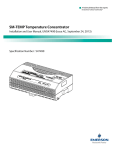
SM-TEMP Temperature Concentrator that is designed for use in both -48V and +24V
systems.
NetSure™ Power Systems can be operated in conjunction with one or more battery
and/or ambient temperature probes. With a battery probe installed and connected, the
power system is designed to automatically increase or decrease output voltage as battery
temperature decreases or increases, respectively. This maintains an optimum charge
voltage to the battery with respect to temperature, thereby extending battery life.
Each SM-TEMP module receives temperature inputs from up to 8 solid-state temperature
sensors (AD592B type). These are the same temperature sensors currently connected
to the temperature inputs of the SCU, SCU+, ACU, and ACU+ controllers.
The SM-TEMP module provides a 125 kbps CAN output of the temperature of all
connected sensors. There are address DIP switches to allow up to eight (8) SM-TEMP
modules to operate concurrently on the same CAN bus.
The SM-TEMP module provides an analog output of the average or the maximum (DIP
switch configurable) of the temperatures of the connected sensors. The output is a
current source providing 1 μA/K. The output is compatible with the temperature port input
of the SCU, SCU+, ACU, and ACU+ controllers. When multiple SM-TEMP modules are
used, the analog output of only one of the SM-TEMP modules is connected to the
controller’s temperature port input.
When used with an ACU+ (version 3.02 or later), in lieu of connecting the analog output
of the SM-TEMP module to an ACU+ temperature port input, the SM-TEMP module can
simply be connected at the end of the ACU+ CAN bus. Via the CAN bus, the ACU+
reads each temperature probe from each SM-TEMP module.
Page 1
This document is property of Emerson Network Power, Energy Systems, North America, Inc. and contains confidential and proprietary information owned by Emerson Network Power, Energy
Systems, North America, Inc. Any copying, use, or disclosure of it without the written permission of Emerson Network Power, Energy Systems, North America, Inc. is strictly prohibited.