1
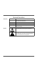
Service/User Manual
2010 Series Chassis
25852-002
October 1999
© 1999 RadiSys Corporation
All Rights Reserved
Printed in USA
Limited Warranty
A. RadiSys Corporation warrants that the item sold by it hereunder will be free from defects in materials or
workmanship, under normal use and service, for a period of 2 years from date of shipment. Said item
will meet the specifications in effect at the time of manufacture. RadiSys' sole obligation under this
warranty shall be, at its option, to repair or replace, without charge, any defective component of said
item, within a reasonable period of time.
B. RadiSys Corporation shall not be liable under this warranty for (i) the item that the Buyer alleges to be
defective and was repaired or altered by someone other than RadiSys' designated personnel or authorized
representative, unless such repair or alteration was effected pursuant to prior written approval of
RadiSys, or (ii) where the Buyer fails to notify RadiSys of any alleged defect within the period of
warranty, or (iii) where the Buyer fails to return the allegedly defective item to RadiSys Corporation, in
Houston, Texas, USA, freight prepaid, or (iv) where the item was altered or damaged in a way which
RadiSys reasonably determines to affect the performance and reliability of the item, or (v) where the
item was subject to misuse, neglect, or accident. The rights and remedies granted to the Buyer under this
paragraph constitute the Buyer's sole and exclusive remedy against RadiSys Corporation, its officers,
agents, and employees, for negligence, inexcusable delay, breach of warranty, express or implied, or any
other default relating to the item or RadiSys' duties to eliminate any errors.
This warranty supersedes any other warranty, whether expressed, implied, or statutory, including but not
limited to any warranty for fitness of purpose, merchantability, or freedom from infringement or the like, and
any warranty otherwise arising out of any proposal, specifications, or sample. Furthermore, RadiSys
Corporation neither assumes nor authorizes any person to assume for it any other liability.
The software included with this equipment is warranted only in accordance with the terms of its license
agreement. Except as warranted in that license agreement, the manufacturer of the software disclaims all
warranties and conditions with regard to the software, including all implied warranties and conditions of
merchantability, fitness for a particular purpose, title, and non-infringement.
Every effort has been made to ensure that the information provided in this manual is complete and accurate.
However, technical inaccuracies or typographical errors may be inadvertently included. RadiSys assumes no
responsibility for any errors that may be contained in this document. RadiSys makes no promise to update or
keep current the information contained in this document. Information in this document, including product
specifications, is subject to change without notice.
Any rights not expressly granted herein are reserved.
All tradenames referenced are the service mark, trademark, or registered trademark of the respective manufacturer.
i
2010 Series
Service/User Manual
Important
Always use caution when handling or operating the equipment. Only qualified and trained electronics
service personnel should access the equipment. Use extreme caution when installing or removing
components. For additional information, please contact RadiSys Technical Support at (800) 438-4769 or
(713) 541-8200 Monday through Friday between 7:00 a.m. and 6:00 p.m., Central Time, Continental USA.
Wichtig
Arbeiten am System bzw. Betrieb des Systems, sollten immer mit der nötigen Vorsicht vorgenommen
werden. Nur qualifiziertes und ausgebildetes Fachpersonal sollte am Inneren des Gerätes arbeiten. Beim
Installieren und Entfernen von Komponenten ist besondere Vorsicht geboten.
Für weitere Informationen wenden Sie sich bitte an den Technical Support von RadiSys:
• USA:(800) 438-4769 oder (713) 541-8200 Montags bis Freitags von 0700 Uhr bis 1800 Uhr, Central USA.
• International:+31-36-5461072 Montags bis Freitags von 0900 Uhr bis 1800 Uhr. (CET GMT +1.00)
Changes or modifications not expressly approved by RadiSys Corporation could
void the product warranty and the user's authority to operate the equipment.
Service/User Manual
2010 Series
ii
Notice
This equipment has been tested and found to comply with the limits for a Class A digital device, pursuant to
Part 15 of the FCC Rules. These limits are designed to provide reasonable protection against harmful
interference when the equipment is operated in a commercial environment.
This equipment generates, uses, and can emit radio frequency energy and, if not installed and used in
accordance with this instruction manual, may cause harmful interference to radio communications.
Operation of this equipment in a residential area is likely to cause harmful interference, in which case, the
user will be required to correct the interference at the user's expense.
This device complies with Part 15 of the FCC Rules. Operation is subject to the following conditions:
• This device may not cause harmful interference
• This device must accept any interference received, including interference that may cause undesired
operation
Any change or modification not expressly approved by the manufacturer is prohibited and could void the
user's authority to operate the equipment.
iii
2010 Series
Service/User Manual
Document Conventions
Typography
Symbols
Title Case
Bold Title Case
Titles of menus, windows, tabs, lists, and groups.
Names of menu items, fields, buttons, icons, check boxes, list
items, group items, and keystrokes.
UPPER CASE
Acronyms and abbreviations.
Italics
Emphasis.
Sans Serif Type
Items in tables, illustrations, and notations.
Monospace Type Output from a printer or monitor. Graphic items will be
displayed as an image.
Notice:
This symbol indicates an item for special consideration.
Warning:
This symbol indicates the presence of a potential hazard that can
cause personal injury. Only qualified and trained electronics
service personnel should access the equipment.
Service/User Manual
2010 Series
iv
Customer Support
Calling
Technical
Support
Step
1
2
Action
Have the RadiSys product model and serial number available.
• In the Continental USA, Monday — Friday, 7:00 a.m. — 6:00 p.m., Central Time, dial
1-800-438-4769 in the USA. Outside the USA, dial 713-541-8200 (add long distance/
international access codes).
• In Europe, Monday — Friday, 8:00 a.m. — 6:00 p.m., dial +31-36-5461072.
Returning
Products for
Service
Step
1
2
Action
Have the RadiSys product model and serial number available.
• In the Continental USA, Monday — Friday, 7:00 a.m. — 6:00 p.m., Central Time, dial
1-800-438-4769 in the USA. Outside the USA, dial 713-541-8200 (add long distance/
international access codes).
• In Europe, Monday — Friday, 8:00 a.m. — 6:00 p.m., dial +31-36-5461072.
When you are assigned a Returned Goods Authorization (RGA) number from a
Technical Support Representative, place it, along with the product serial number, on the
packaging materials and correspondence. The factory will be unable to accept delivery
without these numbers.
Note: The factory does not accept RGA's sent freight collect.
3
Accessing
the Website
http://www.radisys.com
Upon receiving your equipment, inspect the packaging, shipping materials, and contents.
If damaged, return the equipment to RadiSys in the original packaging and shipping materials.
If you are satisfied with your equipment, retain the packaging and shipping materials in case of
future need.
v
2010 Series
Service/User Manual
Table of Contents
Chapter 1
Operations
1
User-Accessible Features ................................................................................. 2
Specifications .................................................................................................... 3
Chapter 2
Service
7
Accessing the Interior ........................................................................................ 8
Internal Features ............................................................................................. 10
Expansion Cards ............................................................................................. 11
Drives and Media............................................................................................. 14
Rack-Mounting the Chassis............................................................................. 18
Wall-Mounting the Chassis .............................................................................. 20
Air Filter Maintenance...................................................................................... 22
Service Manual
2010 Series
vi
List of Figures
1
2
3
4
5
6
7
8
9
11
12
13
vii
Front Features ....................................................................................................................4
Rear Features .....................................................................................................................5
Removing the Top Cover ....................................................................................................9
Internal Components ........................................................................................................12
Internal Components (continued) .....................................................................................13
Installing the Media Access Plate .....................................................................................15
Installing the Floppy Drive Bay .........................................................................................17
Installing the Fixed Drive Bay ...........................................................................................17
Installing the Rack-Mount Adapter....................................................................................18
Rack-Mounting the Chassis ..............................................................................................18
Wall-Mount Panel Holes ...................................................................................................20
Wall-Mounting the Chassis ...............................................................................................21
Installing the Air Filter .......................................................................................................23
2010 Series
Service/User Manual
1
Operations
This chapter discusses functions and features of the equipment that
can be accessed by all users, regardless of training or skill level. The
material contained in this chapter discusses only user-accessible parts
and/or operations.
This chapter discusses the primary features of the 2010 chassis.
If you are familiar with the primary components and functions of the 2010, go to
Chapter 2, “Service,” page 7. Then read this chapter later at your convenience.
Service/User Manual
2010 Series
1
Operations
User-Accessible Features
Overview
The 2010 chassis provides features that permit great flexibility where compact, rugged
equipment is required. This chassis presents a low-cost, highly configurable solution
with exceptional performance.
Models
The 2010 is available in three (3) mounting systems:
• Benchtop
• Rack
• Wall
For more information on model components, see page 18.
Front Access
The following features are accessible from the front of the chassis (Figure 1):
•
•
•
•
Rear Access
IDE/SCSI activity LED
System power LED
Drive bays:
•
One (1) 3½” x 1” drive
•
One (1) 5¼” x ½” CD-ROM drive
The following features are accessible from the rear of the chassis (Figure 2):
•
•
•
•
2
System Reset button
Ten (10) expansion slots
AT-style keyboard connector
Parallel and serial port access
Rocker-style power on/off switch
2010 Series
Service/User Manual
Operations
Specifications
Overview
Listed in the table below are the specifications for the 2010.
Note: These specifications are subject to change without notice.
Environmental
Environmental tolerances are listed in the following table:
Temperature
Humidity
Shock
Vibration
Altitude
System
Operating
0 to +55 °C (32 to 131 °F)
5 — 95% @ 40 °C, non-condensing
15 G @ 10 ms
1 G @ 5 — 150 Hz
15,000 ft (4,572 m)
Non-Operating
-40 to +70 °C (-40 to 158 °F)
0 — 95% @ 40 °C, non-condensing
30 G @ 10 ms
5 G @ 5 — 150 Hz
50,000 ft (15,240 m)
System specifications are listed in the following table:
Dimensions 8.70” W x 8.25” H x 18.10” D (220.98 x 209.55 x 459.74 mm)
Construction All steel with clamshell design for easy service
Indicators
• System reset button
and Controls • System power LED
• IDE/SCSI activity LED
• Rocker-style power on/off switch
Keyboard
AT-style connector on rear panel
Peripherals Access for serial and parallel ports on rear panel
Cooling
• Two (2) 56 CFM fans
• Air filter easily removed and washable
Media
• One (1) 5¼” x ½” CD-ROM drive (user-accessible)
• One (1) 3½” x 1” drive (user-accessible)
• One (1) 3½” x 1” drive (internal)
Expansion
Ten (10) slots
A Note on Thermal Specifications
The technology and power density of the microprocessor is rapidly increasing. The 80386 required less than a few hundred
milliamps of current. The 80486DX4 peaked at less than 1.5 A and dissipated less than 5 watts of power. The 233 MHz Pentium®
processor with MMX™ technology requires up to 6.5 A and dissipates as much as 17 W. The Pentium II processor dissipates
even more. Power levels have increased to a level that greatly affects the ability of the equipment to effectively dissipate energy.
RadiSys is continually working to ensure that its products will conform to thermal specifications. However, we can only work
within known or anticipated hardware and software configurations. One peripheral device installed within a chassis can
significantly alter operating temperature. Also, software applications can cause variations of 20 °C or more. Even the cable
layout within the chassis can affect airflow and thereby performance.
RadiSys validates the operating specifications of its products by testing with the “hottest” possible hardware and software
configuration, to maximize the power supply draw and generate a worst-case scenario. Despite these efforts, the specifications
herein are only benchmarks and should be regarded as such.
Service/User Manual
2010 Series
3
Operations
Figure 1
Front Features
1.
2.
3.
4.
5.
6.
4
5¼” x ½” CD-ROM Drive Bay A. Airflow Vents
3½” x 1” Drive Bay
IDE/SCSI Activity LED
System Power LED
Reset Button
Media Access Plate
2010 Series
Service/User Manual
Operations
Figure 2
Rear Features
Note: This illustration shows the 2010 Chassis with power supply installed.
1.
2.
3.
4.
5.
Wall-Mount Anchor Tabs (2)
Power Input
Power Supply
Switch Guard
Power On/Off Switch
Service/User Manual
6. Power Supply Fan Vent
7. Parallel Port Access
8. AT Keyboard Connector
9. Serial Port Access
10.Expansion Slots
2010 Series
A. Airflow Vents
5
Operations
Notes
6
2010 Series
Service/User Manual
2
Service
This chapter discusses functions and features of the equipment that
can be accessed only by qualified and trained electronics service
personnel. The material contained in this chapter does not discuss any
user-accessible parts or operations. All tasks related to material in this
chapter must be referred to qualified service personnel.
This chapter provides information on the following:
•
•
•
•
•
Service/User Manual
Internal features
Drives and media
Rack-mount bracket
Wall-mount panel
Air filter
2010 Series
7
Service
Accessing the Interior
Safety
It is important to protect yourself and your equipment.
Only qualified, experienced electronics service personnel should access and handle
the equipment.
Es sollte nur qualifiziertes und erfahrenes Fachpersonal am System arbeiten.
To avoid damage or injury, always power-off the system and disconnect all power cords
from their source before handling the equipment.
To help prevent accidental damage caused by static discharge, use a grounding wrist
strap or other static-dissipating device when handling the equipment.
Um Sachschaden und Verletzung zu vermeiden, schalten Sie vor Arbeiten am Gerät
den Netzschalter aus, und ziehen Sie alle Stecker aus den Steckdosen.
Um unbeabsichtigte Schäden durch elektrostatische Entladung vorzubeugen, sollte bei
Arbeiten am System immer ein Erdungsarmband getragen oder andere
elektrostatische Entladungs-Vorsichtsmaßnahmen verwendet werden.
Top Cover
Removal
The procedure for removing the top cover of the 2010 chassis (Figure 3) is outlined in
the following table:
Step
1
2
3
8
Action
Remove all fastening screws from the top, front, and left side panels:
5
• Top:
3
• Front:
• Left Side: 4
Slide the top cover approximately ½” (1.27 cm) toward the front of the chassis.
Lift the top cover up and away from the chassis.
2010 Series
Service/User Manual
Service
Figure 3
Removing the Top Cover
Service/User Manual
2010 Series
9
Service
Internal Features
Overview
The 2010 chassis is designed to be compact and rugged. The interior of the chassis
allows easy access to components and peripherals.
Features
The following internal features (Figure 4 and Figure 5) are incorporated into the 2010
chassis:
•
•
•
•
Up to ten (10) expansion slots
Two (2) 56 CFM cooling fans
Mounts to accommodate various passive backplanes
Floppy Drive Bay:
•
One (1) user-accessible 3½” x 1” drive
•
One (1) user-accessible 5¼” x ½” CD-ROM drive
• Fixed Drive Bay:
•
One (1) internal 3½” x 1” drive
For more information on drives and media, see page 14.
Passive
Backplane
The 2010 Series offers a variety of passive backplanes, presenting a broad assortment
of ISA and PCI slot configurations.
See the Passive Backplane Addendum for more information.
Power Supply
The 2010 Series also offers a variety of power supplies, supporting multiple input
voltages. Each power supply is equipped with features such as over voltage and over
current protection, and a high-volume cooling fan.
See the Power Supply Addendum for more information.
Cable Access
Access holes for cable routing are provided at the following locations in the chassis:
• Card Guide Bracket (Figure 4): provides access for the system LED cables, the
reset button cables, and the fan power cables.
• Backplane Mounting Tray (Figure 5): provides access for serial and parallel
cables routed to connectors mounted on the rear panel of the chassis.
10
2010 Series
Service/User Manual
Service
Expansion Cards
Installation
Before installing expansion cards into the 2010 (Figure 4 and Figure 5), consult the
documentation provided with each card. You should follow the manufacturer’s
instructions for installing the card.
To avoid damage or injury, always power-off the system and disconnect all power cords
from their source before handling the equipment.
To help prevent accidental damage caused by static discharge, use a grounding wrist
strap or other static-dissipating device when handling the equipment.
Um Sachschaden und Verletzung zu vermeiden, schalten Sie vor Arbeiten am Gerät
den Netzschalter aus, und ziehen Sie alle Stecker aus den Steckdosen.
Um unbeabsichtigte Schäden durch elektrostatische Entladung vorzubeugen, sollte bei
Arbeiten am System immer ein Erdungsarmband getragen oder andere
elektrostatische Entladungs-Vorsichtsmaßnahmen verwendet werden.
Card-End Slot
A full-length expansion card will reach from the expansion slot at the rear panel of the
chassis to a card guide mounted on the card guide bracket. The card guide reduces
lateral movement of the expansion card and helps prevent its being dislodged.
The card guides can be individually positioned on the card guide bracket to
hold either ISA or extended-length PCI cards.
Retention
Cushions
The 2010 utilizes two cushions affixed to the underside of the chassis top cover for the
purpose of securing expansion cards in place. By gripping the top of full-height
expansion cards, the retention cushions greatly reduce movement of expansion cards
and further help prevent cards from being dislodged.
Service/User Manual
2010 Series
11
Service
Figure 4
Internal Components
Note: This illustration shows the BP10-C2P6 passive backplane installed.
1.
2.
3.
4.
5.
12
Expansion Slots (10)
Passive Backplane
Speaker
Chassis Cooling Fan (2)
Fan Bracket
6. Card Guide Bracket
7. Floppy Drive Bay:
3½” x 1” and 5¼” x ½”
8. IDE/SCSI Activity LED
9. System Power LED
2010 Series
10. Reset Button
11. Cable Access Hole
12. Fixed Drive Bay:
3½” x 1”
Service/User Manual
Service
Figure 5
1.
2.
3.
4.
Internal Components (continued)
Expansion Slots (10)
Serial Port Access
Cable Access Hole
Parallel Port Access
Service/User Manual
5.
6.
7.
8.
Backplane Mounting Tray
Backplane Mounting Posts (8)
Speaker Mounting Posts (2)
Fan Bracket
2010 Series
9. Card Guide Bracket
10. Card Guides (10)
13
Service
Drives and Media
Overview
The following media can be installed in the 2010 chassis:
• One (1) user-accessible 3½” x 1” drive
• One (1) user-accessible 5¼” x ½” CD-ROM drive
• One (1) internal 3½” x 1” drive
Media Access
The 2010 chassis is designed to allow easy access and installation of media. The top
cover features a media plate that provides quick access to the drive bays without
needing to remove the top cover (Figure 6). Drives can be removed and installed with a
minimum of time and effort.
The procedure for installing the media access plate on the chassis is outlined in the
following table:
Step
1
2
3
Action
Place the media access plate against the front panel of the chassis.
Note: Orient the media plate so that the drive faces align with the access
openings in the media plate.
Fasten the three (3) screws through the holes at the top edge of the media
access plate.This will secure the media plate to the chassis.
Fasten the two (2) screws through the holes at the bottom edge of the media
access plate.
If using the rack-mount or wall-mount accessories, see page 18.
• If using the rack-mount adapter, the two (2) screws at the bottom edge of
the media access plate must be installed after the rack-mount adapter.
• If using the wall-mount panel, the two (2) screws at the bottom edge of the
media access plate are replaced by the wall-mount panel thumbscrews.
14
2010 Series
Service/User Manual
Service
Figure 6
Installing the Media Access Plate
If using the rack-mount or wall-mount accessories, see page 18.
Service/User Manual
2010 Series
15
Service
Floppy Drive
Bay
The following media can be accessed from the chassis front panel (Figure 7):
• One (1) 3½” x 1” drive, typically a floppy disk drive
• One (1) 5¼” x ½” CD-ROM drive
The procedure for installing user-accessible drives in the floppy drive bay is outlined in
the following table:
Step
1
2
3
4
5
6
Action
Install the drive(s) in the floppy drive bay.
Note: Orient the controller and power headers for each drive toward the
interior of the chassis.
Insert the drive bay into the left side of the bay area in the chassis.
Align the four (4) keyholes in the bottom of the bay with the mounting tabs on
the floor of the chassis.
Slide the bay approximately ¼” (.635 cm) toward the interior of the chassis.
This will anchor the drive bay keyholes against the mounting tabs on the floor
of the chassis.
Fasten the two (2) screws through the brackets on the drive bay to the card
guide bracket. This will secure the drive bay in the chassis.
Connect the controller and power cables for each drive.
If a 5¼” x ½” CD-ROM drive is not used, a blank panel can be installed to
close the access opening in the media plate.
Fixed Drive
Bay
One (1) 3½” x 1” drive, typically a hard disk drive, can be installed in the fixed drive
bay (Figure 8).
The procedure for installing a drive in the fixed drive bay is outlined in the following
table:
Step
1
2
3
4
5
6
16
Action
Install the drive in the fixed drive bay.
Note: Orient the controller and power headers for the drive toward the interior
of the chassis.
Insert the drive bay into the right side of the bay area in the chassis.
Align the two (2) keyholes in the bottom of the bay with the mounting tabs on
the floor of the chassis.
Slide the bay approximately ¼” (.635 cm) toward the interior of the chassis.
This will anchor the drive bay keyholes against the mounting tabs on the floor
of the chassis.
Fasten the two (2) screws through the brackets on the drive bay to the card
guide bracket. This will secure the drive bay in the chassis.
Connect the controller and power cables for the drive.
2010 Series
Service/User Manual
Service
Figure 7
Installing the Floppy Drive Bay
Figure 8
Installing the Fixed Drive Bay
Service/User Manual
2010 Series
17
Service
Rack-Mounting the Chassis
Overview
The 2010 chassis can be installed in a conventional cabinet or rack, being placed on brackets or a
shelf (Figure ). To facilitate this, the chassis can be equipment with an adapter that mounts on the
front of the chassis (Figure 9). The rack-mount adapter secures the chassis to the brackets or
shelf.
Adapter
Installation
The procedure for installing the rack-mount adapter is outlined in the following table:
Step
1
2
3
Figure 9
Action
Remove the two (2) screws from the holes at the bottom edge of the media
access plate.
Note: Do not remove the three (3) screws at the top edge of the media plate.
Place the rack-mount adapter against the media access plate.
Note: Orient the rack-mount adapter so that the two (2) open holes align with
the holes at the bottom edge of the media access plate.
Replace the two (2) screws at the bottom edge of the media access plate,
securing the rack-mount adapter to the media plate.
Installing the Rack-Mount Adapter
Mechanical Loading: When rack mounting the 2010 on a rack shelf or enclosure, care should
be taken to insure even side-to side loading The load should not be cantilevered outside of
the supporting rails such that it presents a tip-over hazard to installation or service personnel.
The chassis can be safely lifted, handled and installed by one person without need for lifting
hooks or equipment.
18
2010 Series
Service/User Manual
Service
Figure 10
Rack-Mounting the Chassis
Installation notes for rack mount
and/or enclosed operation.
1)Elevated Operating Ambient
Temperature: When the 2010 chassis
is installed in a closed or multi-unit
rack assembly, care should be taken
to insure that the cooling air supply is
sufficient to maintain the the
operating ambient temperature at or
below 55 degrees C. Consideration
should be given to recirculation of
cooling air inside the enclosure and
the total heat load (in watts)
generated by all equipment within
the rack enclosure.
2) Reduced airflow: Care should be
taken to insure that mounting the
equipment on a rack shelf in an
enclosure OR in close proximity to
other equipment does not
compromise the flow of cooling air
to the 2010 chassis. A minimum clear
distance of 3 inches front and rear
should be provided to allow the free flow of cooling air to and from the chassis. Obstructing the
airflow by placing doors or other equipment closer than three inches should be accompanied by
lowering the maximum operating temperature of the cooling air supply
.
Circuit overloading: When connecting the equipment to the AC circuits, the circuits should
be sized to safely provide all the amperage required by the all the equipment in the rackmounted enclosure. At a minimum, the supply circuit should be capable of providing
amperage equal to the sum of all the rating plate amperages of the equipment contained in
the rack/enclosure, plus 20-25% to provide for inrush current peaks.
Reliable Earthing: Reliable earthing of rack mounted equipment should be
provided. Each piece of equipment within the rack/enclosure should be reliably
grounded to the branch ground. Care should be taken when using power strips
that the ground integrity through the strip is maintained.
Service/User Manual
2010 Series
19
Service
Wall-Mounting the Chassis
Overview
The 2010 chassis can be installed onto a panel that is permanently mounted on a wall.
The wall-mount panel is designed so that the 2010 chassis can quickly be removed and
replaced.
Panel
Installation
The mounting holes of the wall-mount panel are set in a four-way keyhole pattern
(Figure 11). This allows the wall-mount panel to be installed in virtually any position,
so that the chassis can be oriented up, down, left, or right. This mounting system will
accommodate a broad range of spacing considerations, allowing the the 2010 to be
installed in virtually any tight space.
Figure 11
Wall-Mount Panel Holes
Chassis
Installation
After the wall-mount panel has been installed, the chassis can be secured to the panel.
The procedure for installing the chassis onto the wall-mount panel is outlined in the
following table (Figure 12):
Step
1
2
3
4
20
Action
Rotate the front of the chassis upward approximately fifteen degrees (15°), so
that the rear of the chassis is lowered toward the wall-mount panel.
Insert the two (2) chassis anchor tabs into the anchor slots on the rear of the
wall-mount panel.
Rotate the front of the chassis downward toward the wall-mount panel until the
bottom of the chassis meets with the panel.
Fasten the two (2) thumbscrews at the front of the wall-mount panel to the
holes at the bottom edge of the media access plate, securing the chassis onto
the wall-mount panel.
2010 Series
Service/User Manual
Service
Figure 12
Wall-Mounting the Chassis
Service/User Manual
2010 Series
21
Service
Air Filter Maintenance
Overview
The primary airflow intake for the 2010 chassis is through the vents in the front panel.
Behind these vents is an industrial air filter. The air filter is firmly secured inside the
front panel.
Maintenance
The air filter must be maintained regularly to ensure efficient thermal control within the
chassis. It is recommended that the filter be cleaned at least once every month.
Note: It may be necessary to clean the filter more frequently, depending on the level of
airborne particles in the work environment.
Clean the filter using a mild soap and water solution. Thoroughly dry the filter before
reinstalling it in the chassis.
Failure to regularly clean the air filter can cause damage to the equipment
and could void the warranty.
Installation
While in use, the filter is firmly secured inside the chassis top cover. However, the filter
can easily be removed and replaced (Figure 13).
The procedure for installing the air filter is outlined in the following table:
Step
1
2
3
4
22
Action
Remove the chassis top cover.
Note: For more information, see page 8.
Align the air filter with the five (5) Velcro tabs inside the top cover.
Note: The top-right corner of the filter should be placed against the inside
corner of the top cover, where the top, front, and side panels meet.
Press the air filter firmly to the Velcro tabs.
Note: This will secure the filter inside the top cover.
Replace the chassis top cover.
2010 Series
Service/User Manual
Service
Figure 13
Installing the Air Filter
A. Velcro Tabs
Service/User Manual
2010 Series
23
Service
Notes
24
2010 Series
Service/User Manual