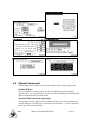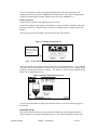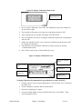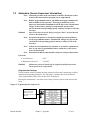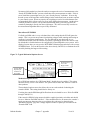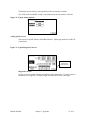
1
Extruder Inductive Proximity Switch
The extruders RPM must be reported to the GH-M controller for the system to function. To
accomplish this, an inductive proximity switch is provided to let the GH-M controller know
the RPM of the extruder. This switch should be field mounted in an appropriate way to read
the extruder’s true RPM. It is important this switch is reading the actual RPM of the
Extruder, and not an RPM before a gearbox, for example. Chapter 3 will detail the
installation and wiring of this component. Because it is field mounted, wiring of the
proximity switch will NOT be done at the factory and we do not provide any custom
mounting brackets for your application as these vary depending on the equipment.
This measurement can also be achieved by writing the extruder’s rpm through
communications (see document at the end of this manual for details). If this is done through
communications then it eliminates the need to install the extruder proximity switch.
Surge Hopper
The surge hopper is located on top of the GH-M frame. These hoppers store a supply of
material to fill the weigh hopper. The surge hopper is sized based on the total throughput of
the extrusion rate monitoring system. Each surge hopper contains a 24V DC solenoid that is
used to open and close the internal dump cone. The internal urethane dump cone is
mechanically opened and closed with a compressed air cylinder.
The rate monitor’s surge hopper does not include any level indication devices as standard
equipment. Optional surge hopper low-level sensors are available. The rate monitor
controller will alarm if it runs out of material while trying to fill the weigh hopper, but lowlevel sensors will alert floor personnel to the problem sooner. If an optional low-level sensor
is purchased, it will activate a visual alarm. This optional proximity switch can be mounted
anywhere the customer desires and is not mounted unless specifically requested.
The refill system is equipped with a manual key switch to open and close the surge hopper.
This three position key switch is located on the front of the PLC enclosure.
Figure 5: Typical Surge Hopper
Figure 6 Refill Switch Positions
Position
AUTO
Description
The rate monitor controller automatically controls surge hopper
functions.
OPEN
Dump cone gate open all the time
CLOSE
Dump cone closed all the time
Bulletin Number
Chapter 2: Functional Description
15 of 61