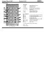
1
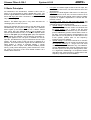
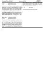
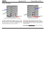
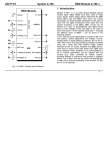
DOEPFER
System A-100
X-treme Filter A-106-1
1. Introduction
Fig. 1: A-106-1 Controls and In/Outputs
Module A-106-1 is an unique low/high pass filter and has it's
origin in our experiments to built a MS20 filter clone. In
contrast to other filter designs it has different audio inputs
for low and high pass, but only one audio output. The type
of filter (12dB low pass, 6dB high pass or any mix) is
defined by the shares of the audio signal fed to the
corresponding inputs. Even two different audio signals can
be used as low and high pass input. A special feature is the
polarizer at the high pass input that allows to add/subtract
the high pass to/from the low pass share, leading to pseudo
band pass and notch responses (details concerning pseudo
in the next chapter).
Another special feature are the clipping controls, which
allow independent adjustment of the positive and negative
clipping level. The resonance goes up to self-oscillation, but
with a clearly different behaviour than on other filters. At
certain resonance and clipping settings the self-oscillation
generates rectangle or short sawtooth shaped pulses.
In general the A-106-1 is a very strange and awesome filter
and far away from being perfect (e.g non-linear control
scale, self-oscillation with all sorts of waveforms except
sine, a lot of roaring, rattling, noise or other unpredictable
sounds at high distortion and resonance settings, high
distortion or audio level overrides the resonance, significant
CV feedthrough …). But the A-106-1 has a lot of character –
probably much more than any other filter of the A-100 – and
is able to generate filter sweeps which are not possible with
any other filter.
1
X-treme Filter A-106-1
System A-100
2. Basic Principles
As mentioned in the introduction, module A-106-1 has it's
origin in our experiments to built a MS20 filter clone. The
famous original MS20 included two filters: a 12 dB low pass
and a 6dB high pass filter connected in series, both with a
very special design.
Remark: The MS20 high pass if very often described as
12dB high pass, but this is not true.
During our research we found a way to use the same circuit
simultaneously as low pass and high pass for 2 different
audio signals (a bit similar to the A-101-1 Steiner Vactrol
filter, which also has different audio inputs available, but
with the special MS20 circuit). For this two separate audio
inputs for low pass (LP) and high pass (HP) with separate
level controls are available. The sockets are normalled, i.e.
the signal applied to the LP input is available for the HP
input too, provided that no plug is inserted into the HP input
socket. The level control of the HP input is realized as a
polarizer. This means that the signal can be added with the
same polarity (+ range) or opposite polarity (- range)
compared to the LP input. This feature enables pseudo
notch (+) and pseudo band pass (-) filter functions too. From
our point of view this is the most flexible solution as it
enables these functions:
2
•
•
•
DOEPFER
Low pass: the audio signal is fed to the LP input, HP
level control is set to zero, LP level control is set to the
desired level
High pass: the audio signal is fed to the LP or HP input,
LP level control is set to zero, HP level control is set to
the desired level (in this special case it does not matter
if positive or negative amplification is chosen with the
polarizer control)
Low pass / high pass mix with one audio signal: the
audio signal is fed to the LP input, LP and HP level
controls are set to the desired levels.
o special setting 1: if the level controls for LP and HP
are set in a way that both levels are identical with
the same polarity (i.e. + range of the HP level
control) and no or little distortion only one obtains a
pseudo notch filter (pseudo means that the notch is
far away from being perfect, the attenuation in the
pass band is not as good as for other filters of the
A-100 system, please refer to the frequency
response curves for details)
o special setting 2: if the level controls for LP and HP
are set in a way that both levels are identical with
the opposite polarity (i.e. - range of the HP level
control) and no or little distortion only, one obtains a
pseudo band pass filter (pseudo means that even
the band pass is far away from being perfect, there
is a significant feedthrough of frequencies below
and above the center frequency, please refer to the
frequency response curves for details)
DOEPFER
o
System A-100
Remark for settings 1 and 2: The original MS20
circuit was not planned for notch or band pass
applications. The pseudo notch and pseudo band
pass filters should be treated as a free bonus and
have the disadvantages mentioned above. The
reason is that the low pass has a 12dB/octave
slope and the high pass has 6dB/octave. This leads
to phase relations that do not allow a "perfect" band
pass and notch simply by adding/subtracting
signals as for other filter designs (for insiders: there
remains always a 90 degree phase shift). For better
notches and band passes other A-100 filters should
be used - or two A-106-1 patched in series (band
pass) or parallel (notch) with suitable frequency
settings.
•
X-treme Filter A-106-1
Low pass and high pass with two different audio
signals: the two audio signals are fed to the LP input
resp. HP input and the level controls for LP and HP are
set to the desired levels. For the +/- control of the HP
input it is essential in this case if the two input signals
are phase correlated (e.g. two different outputs of the
same VCO or VCO output and a frequency divided
signal derived from this VCO) or if there is no fixed
phase correlation between the two signals (e.g. two
different VCOs). In the first case the - and + range of
the HP control leads to different filter results. In the
second case there is no difference, if the + or - range of
the HP control is used.
This design allows even some very special functions: It is
e.g. possible to adjust the controls so that the LP signal
does not distort, but the HP share does (or the other way
round) - alternatively with the same or opposite polarity
compared to the LP signal. For this the LP level has to be
set to a small value so that the signal does not distort. The
HP level control has to be set to a higher value (in the + or range)
so
that
the
HP
share
will
distort.
The variety of controls allows a lot of functions which are not
available for any other filter we know.
3
X-treme Filter A-106-1
System A-100
Low pass (no resonance)
High pass (no resonance)
Pseudo Band pass (no resonance)
Pseudo Notch (no resonance)
Low pass (medium resonance)
High pass (high resonance)
Fig. 2: A-106-1 Frequency Response Curves
4
DOEPFER
DOEPFER
System A-100
During the A-106-1 development we found also that it might
be useful to add controls not available on the original MS20
filters. In the original circuit the filter output level is limited to
about +/– 0.7V by two antiparallel diodes across the
output/resonance amplifier. Removing one or both diodes
leads to noticeable different behaviour of the filter. We
added two rotary controls CL+ and CL- to adjust the effect
of each limiting diode (i.e. from original MS20 behaviour with
fully active limiting diodes to no limiting effect). The
independent control for each diode allows asymmetrical
limiting/amplification that causes a completely new and
sometimes very strange behaviour.
X-treme Filter A-106-1
One of the main effects of the asymmetrical limiting is that in
self-oscillation the filter does not generate a sine wave but
short pulses, if only one of the limiting diodes is activated.
Another effect is that a higher output level of the filter can be
obtained (which is limited to about +/- 0.7V for the original
MS20 circuit). In addition dirty noise effects appear at
certain combinations of the control settings for resonance,
CL+, CL- and input level. The controls CL+, CL-, resonance,
LP level and HP level have to be treated in a common
context: if the input levels are small the CL+ and CLcontrols will have no effect as the signal does not distort at
all because it does not reach the clipping levels. Increasing
the resonance also increases the audio level and the
CL+/CL- controls may now have an effect on the output
level without changing the input level !
Same applies if the resonance control remains unchanged
while the input level increases. Now the CL+ or CL- control
will have an effect as the level reaches the clipping
thresholds. Increasing the audio level may also suppress
the resonance if distortion becomes extreme. The
"teamwork" of the five controls is very complex and has to
be learned by doing and hearing.
Fig. 3 : A-106-1 Clipping functions
The audio inputs are very sensitive to allow even extreme
distortion effects, much more than possible for the original
MS20.
The module is equipped with an insert option for the
resonance feedback loop. This allows to insert other A-100
5
X-treme Filter A-106-1
System A-100
modules into the resonance circuit. The standard application
is to insert a VCA for voltage controlled resonance. But even
other modules - e.g. waveshaper, divider, phaser,
distortion, PLL, wave multiplier, spring reverb, ring
modulator, frequency shifter, BBD or any other audio
processing module - can be inserted to obtain sounds one
has probably never heard before.
On top of this the module is equipped with three frequency
control voltage inputs (CV). One CV input is equipped with a
polarizer. This means that the effect of the external CV (e.g.
envelope from an ADSR generator) to the filter frequency is
positive (+ range) or negative (- range). Especially when the
filter is moved from LP to HP it might be useful to invert the
polarity of the envelope CV. It has to be pointed out that the
frequency response is far away from being 1V/oct but rather
non-linear.
Pay attention that the CV3 and high pass level controls are
polarizers with zero level at the center position. Especially
for the high pass control it is a bit tricky to find the neutral
position. Here are two solutions for this problem:
•
6
Insert an unconnected patch cable or a single 3,5 mm
jack plug into the high pass input (the two terminals of
the plug may even be shortened). For this reason a 30
cm patch cable is added to each A-106-1 module for
free. You may even nip off the jack plug of the cable to
have it available especially for this function.
•
DOEPFER
Change the high pass polarizer into a normal attenuator
by moving the jumper JP4 to the lower position (see
below)
Pay attention that for pure low pass function of the module
the high pass control "HP level" has to be in the neutral
position or even better a dummy plug is inserted into the
high pass input "HP In".
To obtain the filter section of the original MS20 two A-106-1
have to be patched in series (one in LP mode, the other in
HP mode, both with CL+ and CL- set to zero).
The A-106-1 is far away from being a "perfect" filter in an
academic sense. The control scale is non-linear. With selfoscillation all sorts of waveforms except sine are generated.
High distortion and resonance settings lead to roaring,
rattling, noise or other unpredictable sounds. High distortion
or audio level may "kill" the resonance at certain settings.
The filter has a significant control voltage feedthrough. The
"band pass" is not a real band pass as a considerable share
of all frequencies passes through. The notch filter does
attenuate only about 50% at the center frequency - and
many more specialties. But the A-106-1 has a lot of
character - much more than any other filter of the A-100. It is
a very strange and awesome filter - somehow quite the
opposite of the 48 dB ladder filter A-108, which is a very
smooth, warm and predictable filter. The A-106-1 is
definitely not the right choice for "moogish" or "civilized"
sounds but for extreme, exceptional and experimental
sounds - this is why we call the module "X-filter", also to
DOEPFER
System A-100
avoid troubles with the Korg company who is the owner of
the term "MS20". If you want to know more technical details
please look at the document “A-101-1 technical details” on
our website www.doepfer.com (available from the A-101-1
or A-106-1 info page). In this document the basics of the A101-1 (Steiner) and A-106-1 ((Xtreme) filters are described.
There are two jumpers on the module.
•
•
The first jumper is located on the main board A (the
right one with the CL+/CL-/Res. controls) and labelled
JP7A/B. In the upper position A (factory setting) the
output is unbuffered and has a noticeable DC offset
(DC coupled). Unbuffered means that the output load
affects the filter behaviour. In the lower position B the
output is buffered and has no DC offset (AC coupled). If
unexpected behaviour of the A-106-1 output appears
try the lower position (buffered mode).
The second jumper is located on board B (the left one
with the frequency and audio input controls) and
labelled JP4. It is a bit difficult to find as it is located
behind the 10 pin connector that is used to connect the
two boards. It is recommended to remove the female 10
pin connector to change the setting of this jumper. In
the upper position (factory setting) the high pass control
"HP Lev" works as a polarizer (zero = center position).
In the lower position it works as a normal attenuator
with zero at the fully counterclockwise position. If you
do not want to use the polarizer function (i.e.
add/subtract the LP and HP signals) it is recommended
X-treme Filter A-106-1
to move the jumper to the lower position. But in this
case the (-)/(+) front panel printing for the HP level
control is no longer valid.
Clipping control option:
The module is prepared to control the CL+ and CLparameters by using the universal vactrol module A-101-9.
Two pin headers (JP5, JP6, located behind the CL+ control)
are used to establish a connection to the universal vactrol
module A-101-9. This allows voltage control of CL+ and CL. Please refer to the manual of module A-101-9 for details.
7
X-treme Filter A-106-1
System A-100
DOEPFER
3. Overview
!
1
6
"
2
7
§
3
8
&
$
4
/
%
(
5
6 CL+:
7 CL–:
8 Res.:
In- / Outputs:
! CV1:
" CV2:
§ CV3:
$ LP In:
% HP In:
& Res. Insert:
/ Res. Insert:
( Out:
manual frequency control
attenuator for CV2
polarizer for CV3
low pass audio input attenuator
high pass audio input polarizer/
attenuator (*)
positive clipping control
negative clipping control
resonance level control
CV1 input (without attenuator/polarizer)
CV2 input (with attenuator)
CV3 input (with polarizer/attenuator) (*)
low pass audio input
high pass audio input
(normalled to low pass audio input $)
resonance insert (output)
resonance insert (input)
audio output
(*) function depends upon jumper settings
Fig. 4: front panel
8
Controls:
1 Frequ. :
2 CV2:
3 CV3:
4 LP Level:
5 HP Level:
Width: 14HP
Current: 30 mA
System A-100
DOEPFER
X-treme Filter A-106-1
4. Controls and In- / Outputs
!
1
"
2
§
3
CV1:
Frequ. :
CV2:
CV2:
CV3:
CV3:
CV1 input
manual frequency control
CV2 input
attenuator for CV2
CV3 input
polarizer/attenuator for CV3
This group of elements is responsible for the filter
frequency. Knob 1 Frequ. is used to adjust the frequency
manually. Three CV inputs (CV1 !, CV2 ", CV3 §) are
available to control the frequency by external control
voltages (e.g. ADSR, LFO, random, sequencer). The
sensitivity of CV1 is fixed, CV2 is equipped with a normal
attenuator 2, CV3 with a polarizer 3. The neutral position of
the polarizer knob is at it’s center (0). Left from the center
(area marked with a minus sign) the effect of the CV3 is
negative, i.e. an increasing CV3 decreases the frequency.
Right from the center (area marked with a plus sign) it’s
positive, i.e. increasing CV3 increases the frequency.
The control scales of the three CV inputs are non-linear, i.e.
not 1V/octave as CV inputs of many other A-100 modules.
$ LP In:
4 LP Level:
% HP In:
5 HP Level:
low pass audio input
low pass audio input attenuator
high pass audio input
high pass audio input polarizer/
attenuator
Socket $ is the low pass audio input (LP In) with the
assigned attenuator 4. Socket % is the high pass audio
input (HP In) with the assigned polarizer 5. This polarizer
can be converted into a normal attenuator by changing an
internal jumper (please refer to page 7 for details).
The HP In % is normalled to the LP In $, i.e. if no plug is
inserted into the HP In % the signal applied to the LP In $ is
also used for the high pass section.
For pure LP function the HP Level 5 has to be set
approximately to it's center position. The best way to find
the neutral positon of the HP control is by hearing. Move the
control until the high pass share disappears in the audio
output signal. As it is a bit tricky to find the neutral position
even a dummy plug can be inserted into the HP In socket
for pure LP applications. In this case the normalling between
the sockets LP In and HP In is interrupted.
Both the LP and the HP audio input are very sensitive. With
standard A-100 signals (e.g. VCO) distortion appears
already at medium settings. But the distortion also depends
upon the clipping and resonance settings.
9
X-treme Filter A-106-1
6 CL+:
7 CL–:
System A-100
positive clipping control
negative clipping control
This controls are used to adjust the upper and lower clipping
levels of the filter circuit. At the left position the smallest
clipping level is chosen, i.e. clipping appears even at small
input levels. Turning a clipping control clockwise increases
the clipping level and clipping occurs just at higher levels.
The adjustment of the clipping controls also affects the max.
output level as for higher clipping levels even the max.
output level becomes higher.
The module is prepared to control the clipping functions with
voltages by using the universal vactrol module A-101-9. For
details please refer to page 7 and the A-101-9 user's
manual.
& Res. Insert:
/ Res. Insert:
8 Res.:
resonance insert (output)
resonance insert (input)
resonance level control
This group of elements is responsible for the resonance
functions of the module. Socket / is the input of the
resonance loop and is normalled to resonance output socket
&. If an external module is used to control the resonance
loop (e.g. a VCA), this module has to be inserted between
socket & and socket /. The resonance control 8 is used to
adjust the resonance level manually. Resonance can be
increased up to self-oscillation. As already mentioned in
chapter 2 the controls for level, resonance and clipping
10
DOEPFER
influence each other. E.g. the waveform generated in selfoscillation mode depends upon the settings of the clipping
controls and the resonance, or self-oscillation is reduced or
even "killed" by an excessive audio level.
( Out:
audio output
This socket is the audio output of the module.
DOEPFER
System A-100
X-treme Filter A-106-1
5. User Examples
Voltage Controlled Morphing between LP and HP
Voltage Controlled Resonance
A voltage controlled panning module A-134 is used to
control the shares of the audio signal fed into the LP and HP
inputs of the A-106-1. With an external voltage (Morph. CV)
the relation between LP and HP is adjusted (e.g. LFO,
ADSR, sequencer, random or S&H, Theremin).
The resonance insert is processed by a VCA A-130 to
obtain voltage controlled feedback. Instead of a VCA even
other signal processing modules can be used (e.g. BBD, VC
polarizer, waveshaper/wave multiplier, spring reverb, PLL)
for special effects.
On our web site www.doepfer.com several A-106-1 sound
examples are available.
11
X-treme Filter A-106-1
12
System A-100
DOEPFER