1
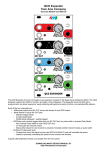
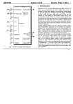
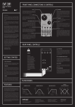
TripFire
User Manual
Features
Trip/Fire: 4hp comparator + Trigger/Gate delay
Comparator features:
• Comparator with external level input or internal level adjustment
• Level control is an attenuvertor
• Jumper selectable polarity on comparator output
• Comparator output normalled to the delay input
• LED output indicator
Delay features:
• Switch selectable trigger/gate delay
• Jumper selectable fast/slow delay time
• LED indication of input and output status
TripFire Description
The TripFire is a combination comparator and trigger/gate delay.
The comparator takes a bipolar input and compares it to a level set by the LEVEL control. If a patch cord is plugged into the
REF input, it is compared to the input signal, and the LEVEL control turns into an attenuverter for the REF input. An LED
shows the output state. The output of course is available at the OUTPUT jack. The polarity of the comparator output is
jumper selectable.
The DELAY section operates as a trigger or gate delay. The IN jack, normalized to the comparator OUTPUT jack, takes
triggers or gates and delays them for a duration set by the DELAY control. The G/T button sets the delay mode, and a
three color LED shows the current mode. An LED shows the output state, and as always the output is on the OUTPUT jack.
The delay modes are:
Mode
Trigger – trigger in
Gate-Off – gate on is delayed
Gate – gate in
Function
Delayed trigger out
Gate off follows input (no delay)
Delayed gate out
LED Color
Green
Yellow
Red
Delay time is about 1 second maximum, with a jumper that makes the delay about 8 seconds maximum.
Module is 4HP and draw TBD mA at
Front Panel Interface
Comparator
In: Affects the positive half of the input waveform. This input has an attenuator and a bias control for presetting the level.
Ref: Affects the negative half of the waveform. This input has an attenuator and a bias control for presetting the level.
Level: Affects both halves of the waveform. As the Input increases, the positive half of the input waveform warps more,
while the negative half warps less. This input has an attenuator and a bias control for presetting the level.
LED: Shows state of the comparator output.
Out: Affects both halves of the waveform. As the Input increases, both the positive and the negative half warps more. This
input has an attenuator and a bias control for presetting the level.
Delay
In: Trigger/gate input
Output:
Operation
COMPARATOR
Comparator
IN
The comparator is a bipolar device which, of course, compares two levels and
produces an output based on that comparison. The IN jack carries one signal
directly to the comparator, while the REF jack carries the other through an
attenuverter controlled by the LEVEL trim. If there is nothing in the REF jack, then
the LEVEL trim provides a steady DC level.
OUTPUT
REF
LEVEL
+5V
REF
IN
This diagram shows the comparator
operation. The output is high when the IN
signal exceeds the REF level.
Note: there is a pair of polarity jumpers on
the back of the module. These are labeled
POS and NEG. The diagram shows the
operation with the POS jumper in place.
When the NEG jumper is in the polarity of the
output is opposite what is shown.
DO NOT JUMPER BOTH POS AND NEG AT THE SAME TIME. MODULE DAMAGE WILL OCCUR.
OUT
DELAY
Delay
Operation
The delay section takes in a trigger or gate signal and delays it for a fixed time set by the DELAY control. The
delay range is about 1mS to 1Sec. There is a jumper on the back of the module that will make the delay about
8mS to 8 Sec. The IN jack of the delay section is normalized to the output of the comparator section.
Figure 1 Trigger Delay
Delay
The delay block is actually an event recorder which timestamps the incoming edges and plays them back with a
delay. The unit is capable of recording and storing 220 events at any time. As the edges are played back they
are removed from memory, freeing the memory for new edge events.
Because this is a recording device it is possible to overflow the memory. This will happen if very fast pulse trains
are fed to the delay section. The output may start to lose events or behave erratically.
The delay module has 3 modes: Trigger, Gate-Off, and Gate.
Gate-Off mode: The delay block senses both edges on the input. The rising edge is delayed but the falling
edge occurs as soon as the input falling edge occurs. This mode is useful when playing from a keyboard where
you want the notes to end as soon as the key is lifted. Figure 2 illustrates this. Note: in this mode if the gate
goes low before the delay times out there will be no output. This is because in this mode the input gate going
low causes the output to go low, and it has not gone high yet, hence no output.
Gate mode: The delay block senses both edges on the input and are delayed to produce the output. This
mode is preserves the gate on time.
Figure 2 Gate-Off Delay
Delay
Trigger mode: The delay block captures rising edges only and produces a delayed trigger pulse. See figure 1.
Figure 3 Gate Delay
Module Width
Module Depth
Power Connector
Power Requirements
Input Impedance
Output
4HP (20mm)
43mm
Standard Doepfer 16 pin
± 12 Volts at 20mA Max
20K Ohms
Short circuit protected