1
doepfer
System A - 100
1. Introduction
Module A-154 is a supplement to the Analog/Trigger
Sequencer A-155. It offers a lot of new features that are
not available in the basic control unit of the A-155. The
A-154 is used to replace the control unit of one or two
A-155, i.e. the section marked "Control" with Start / Stop
/ Step / Reset buttons and inputs in the upper left corner
of the A-155 front panel. If the A-154 is used to control
the A-155 the control section of the A-155 is put out of
action.
These are the most important features of the A-154:
• 5 different running modes: forward, backward, pendulum, random, CV controlled step adressing. All
modes are available as loop or one-shot
• Manual and voltage controlled selection (with attenuator) of the running mode
• 5+1 LED display for the 5 different current modes
and one LED for loop/one-shot display
• Manual and voltage controlled selection (with attenuator) of first and last step of the sequence
• In the "CV Controlled Step Address" mode the First
Step section is used to determine the active sequencer step (in this mode the first/last step feature is not
available). Consequently manual and voltage controlled selection of the active step is possible
Sequencer Controller A-154
• Internal voltage controlled clock generator with
manual and voltage controlled (with attenuator)
clock rate, enables variable time length for each
step, e.g. controlled by one of the analog rows of the
A-155
• Skipping of steps, e.g. the gate row of the A-155 can
be used to control the skipping of steps
• LED display of the clock signal
• Manual and voltage controlled (with attenuator)
pulse length of the clock signal. This features enables different gate length (at the same clock rate) for
each step, e.g. one of the CV outputs of the A-155
can be used to control the PW
• One or two A-155 can be controlled from the A-154
• 8/16 step mode: In combination with two A-155 one
can select between parallel (8 steps) or serial operation (16 steps). The serial operation requires additional voltage controlled switches (e.g A-150)
• Manual and voltage controlled selection between
"old" control unit of the A-155 and A-154 control
(A-154 Master on/off function)
• With the One-Shot modes the A-155/A-154 combination can be used e.g. as a complex envelope
generator. One analog row determines the levels of
the envelope. The second analog row can be used to
adjust the time length for each step
• The A-154 requires at least one A-155
1
A-154 Sequencer Controller
System A - 100
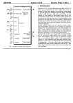
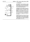
Fig.1: Overall view
2
doepfer
System A - 100
doepfer
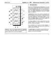
2. Basic principles
The current step position of the A-155 is determined
by the current address of the sequence. The address
reaches from 1 to 8 as the A-155 has eight steps
available. Internally the address is formed by three
digital address signals A0, A1 and A2 having the
valencies 1 (A0), 2 (A1) resp. 4 (A2). The connection
between step position and the digital values for A0, A1
and A2 is as follows:
Step
position
A0
A1
A2
1
low / 0
low / 0
low / 0
2
high / 1
low / 0
low / 0
3
low / 0
high / 1
low / 0
4
high / 1
high / 1
low / 0
5
low / 0
low / 0
high / 1
6
high / 1
low / 0
high / 1
7
low / 0
high / 1
high / 1
8
high / 1
high / 1
high / 1
Sequencer Controller A-154
The "old" control unit of the A-155 simply generates
the address signals A0, A1 and A2 so that the steps
1-8 are selected one after another. If the A-154 is
used to drive the A-155 the old control unit (i.e. the
section with Start/Stop/Step/Reset buttons and input
sockets) is no longer active and the A-154 calculates
the address signals A0, A1 and A2 in a more sophisticated way. The type of address succession depends
upon the selected mode (forward, backward, pendulum, random, CV addressed, loop/one shot).
In serial mode (i.e. if the A-154 is used to drive two
serial running A-155) another address signal A3 with
valency 8 is generated. This signal is used to distinguish between the first and second A-155 by means
of voltage controlled switches.
In addition the A-154 even generates clock signal with
both voltage controlled rate and pulsewidth.
If the A-154 is used to control the A-155 the previous
connection between the "old" control unit and the
analog resp. trigger/gate rows of the A-155 has to be
disconnected and the rows have to be connected to
the corresponding signals of the A-154. In the appendix this procedure is described in detail. The combination of A-154 and A-155 does not work before this
procedure is carried out. It is not sufficient simply to
assemble the A-154 into the A-100 frame !
3
A-154 Sequencer Controller
System A - 100
doepfer
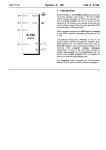
3. Overview
1c
1a 1b
2a 2b
3a 3b
4a 4b
5a 5b
!
6a
"
6b
§
$
%
&a
&b
7a 7b
6c
&c
/
6d
&d
9
8
(
)
4
System A - 100
doepfer
Sequencer Controller A-154
Controls:
Inputs / Outputs:
1a Manual Mode: Manual Mode control
! Mode CV:
Mode control voltage input
1b Mode CV:
Attenuator for CV input !
" First CV:
First control voltage input
1c
Mode display (6 LEDs)
§ Last CV:
Last control voltage input
2a Manual First:
Manual First control
$ Clock CV:
Clock control voltage input
2b First CV:
Attenuator for CV input "
% PW CV:
Pulsewidth control voltage input
3a Manual Last:
Manual Last control
&a Ext. Start:
External Start input
3b Last CV:
Attenuator for CV input §
&b Ext. Stop:
External Stop input
4a Manual Clock: Manual Clock control
&c Ext. Reset:
External Reset input
4b Clock CV:
Attenuator for CV input $
&d Ext. Clock:
External Clock input
5a Manual PW:
Manual Pulsewidth control
/ 1-8/9-16:
A3 output (1-8 / 9-16)
5b PW CV:
Attenuator for CV input %
( ext. Master:
External master control input
6a Manual Start:
Start button
) Clock Out:
Clock output (2x)
6b Manual Stop:
Stop button
6c Manual Reset: Reset button
6d Manual Clock: Clock button
7a 8/16 Steps:
8/16 steps switch
7b 9-16/A3:
LED display of A3/output /
8 Man On/Off:
A-154 master switch
9 Clock:
Clock display
5
A-154 Sequencer Controller
System A - 100
4. Controls
1a Manual Mode (knob)/ 1c Anzeige (LEDs)
! Mode CV (socket) / 1b Mode CV (knob)
Control 1a is used to select the desired mode manually.
This parameter can also be modulated with an external
control voltage (CV) applied to socket ! (e.g. slow LFO,
foot controller, Theremin). Control 1b is used to attenuate the external CV and consequently the influence
of the external CV. The current mode is displayed by
means of the 6 LEDs 1c.
These modes are available:
•
•
•
•
•
Forward
Backward
Pendulum
Random
CV Controlled
(step position is controlled by an
external CV applied to the First CV
input ")
In addition each mode - except the CV controlled mode
- is available even as One Shot. This means that the
sequence stops as soon as the final step is reached.
For the first 3 modes the number of steps to reach the
final step is exactly defined. For the random mode the
number of steps required to reach the final step cannot
be predicted (that's why it is called random).
6
doepfer
Which of the steps is the final step depends upon the
selected mode and the settings of the First and Last
step section (see below). Examples: first step = 2, last
step = 7. In Forward/One Shot mode the sequence stops
at step 7. In Backward/One Shot mode the sequence
stops at step 2.
The CV Controlled mode is not available as One Shot
as in this mode the current position is defined by a
voltage. In this mode the position of the sequence is
controlled by the settings of the First section (i.e. the
position of the manual First control 2a, the external CV
" and the corresponding attenuator 2b)
With increasing mode CV (resp. turning the manual
mode control 1a clockwise) the modes are selected in
the order as listed above followed by the same modes
as one shots.
The required control voltage at socket ! to reach all
available modes is about 0...+5V (with attenuator 1b at
it's maximum and Manual Mode 1a at it's minimum
position) .
The current mode is displayed with 6 LEDs. 5 LEDs are
used to display the main mode (forward, backward ...).
The separate LED labelled One Shot lights up if additionally the one shot mode is activated. Example: Both the
"Backward" and the "One Shot" LED light up. This
means that the Backward / One Shot mode is selected.
doepfer
System A - 100
2a Manual First (knob)
2b First CV (knob) / " First CV (socket)
3a Manual Last (Regler)
3b Last CV (knob) / § Last CV (socket)
This group of elements is responsible for the First and
Last step of the sequence. For both parameters a
manual control (knobs 2a and 3a) and an external
control voltage input (CV inputs " and §) are available.
The CV inputs are equipped with attenuators (knobs 2b
and 3b). The attenuators are used to adjust the level of
the corresponding external CV and consequently the
influence of the CV.
The required control voltage at the sockets " resp. § to
reach all steps is about 0...+5V (with attenuators 2b
resp. 3b at it's maximum and Manual First 2a resp.
Manual Last 3a at it's minimum position).
In the CV Controlled mode the first/last step function
does not work. Rather the controls and the CV input of
the First section (", 2a and 2b) are used in this mode
for the voltage addressed step position of the sequence. The controls and CV input of the Last section
have no function in this mode.
Note : If the sequencer seems not to work (i.e. it remains
at a fixed position) please check if the settings of first
and last step are the reason for this behaviour. If the
value of the last step is the same or smaller than the
value of the first step the sequence seems to stop ! But
Sequencer Controller A-154
actually always the same step is addressed due to the
settings of first and last step! If you do not want to use
the first/last step function the manual controls should be
set to minimum (2a Manual First) resp. maximum (3a
Manual Last) and no external CVs should be applied
resp. the attenuators (2b and 3b) should be set to
minimum.
4a Manual Clock (knob)
4b Clock CV (knob) / $ Clock CV (socket)
5a Manual PW (knob)
5b PW CV (knob) / % PW CV (socket)
This group of elements is responsible for the internal
clock generator. Both rate (clock) and gate length resp.
pulsewidth (PW) can be controlled independently. For
both parameters a manual control (knobs 4a and 5a)
and an external control voltage input (CV inputs $ and
%) are available. The CV inputs are equipped with
attenuators (knobs 4b and 5b). The attenuators are
used to adjust the level of the corresponding external CV
and consequently the influence of the CV.
The independent control of rate and pulsewidth leads to
a lot of interesting features. E.g. controlling PW by one
of the A-155 CV outputs allows a different gate length
for each step. But the tempo (resp. clock rate) is the
same for the whole sequence.
7
A-154 Sequencer Controller
System A - 100
Another example is to control the clock rate by one of
the A-155 CV outputs. This leads to a different time
length (or different tempo) for each step, i.e. the tempo
is different for each step. If the A-155 Gate output is
used to control the clock rate skipping is possible as
beyond a certain control voltage the step time becomes
extremely short (less than a millisecond) and the corresponding step is practically leaved out.
Beyond it the parameters of the clock generator can be
controlled by other voltages too: e.g. LFO, Random CV,
Theremin, ribbon or foot controller, distance or light
controlled CV and many more.
The required control voltage at the sockets $ resp. % to
cover the complete rate resp. PW range is about 0...+5V
(with attenuators 4b resp. 5b at it's maximum and
Manual Clock 4a resp. Manual PW 5a at it's minimum
position). Beyond about +4.8V at socket $ skipping
occurs (see above).
9 Clock (LED) / ) Clock Out (2 x socket)
The two sockets ) are the output of the internal clock
oscillator (miniature multiple). The internal clock signal is
normalled to socket &d Ext.Clock, i.e. the internal clock
is used as clock source provided that no plug is inserted
into socket &d. LED 9 is the clock display. Pay attention
that for high clock rates (~ above 20 Hz) the human eye
will not be able to follow the LED display and the LED
seems to be permanently on (with dimmed brightness).
8
doepfer
6a Manual Start (button) / &a Ext. Start (socket)
6b Manual Stop (button) / &b Ext. Stop (socket)
6c Manual Reset (button) / &c Ext. Reset (socket)
6d Manual Clock (button) / &d Ext. Clock (socket)
These 4 buttons and sockets have nearly the functions
as those of the "old" A-155 control unit (refer to A-155
manual for details):
•
•
•
•
6a Manual Start:
6b Manual Stop:
6c Manual Reset:
6d Manual Clock:
• &a Ext. Start:
• &b Ext. Stop:
• &c Ext. Reset:
• &d Ext. Clock:
starts the sequence
stops at the current position
resets to first step
advance to next step
positive transition starts sequence
positive transition stops sequence
positive transition prepares jump
to first step (see below)
positive transition triggers
advance to next step
Socket &d Ext.Clock is normalled to the internal clock
generator.
If the sequencer does not run though a clock signal is
applied probably the stop mode is selected. In this case
the start button has to be operated to start the sequence.
Operating the stop button causes the sequencer to stop
at its current position. But no reset to first step is carried
out!
doepfer
System A - 100
Operating the reset button prepares the sequencer to
jump to the first step as soon as the next clock signal (!)
appears. If no clock signal is applied the reset button
seems not to work! We believe that it makes more
sense to carry out the jump to the first step not until the
next positive clock transition occurs. Otherwise the next
clock would cause an advance to step 2 (in forward
mode and first step =1). Especially for synchronous
operation of several sequencers this type of reset control
is more useful from our point of view.
Attention! In this detail the A-154 control differs from the
"old" A-155 control and from other sequencers. For the
A-155 the reset was independent from clock. Operating
the reset button caused to jump to step 1 independent
from the clock signal and the next clock caused an
advance to step 2.
Operating the clock button triggers an advantage to the
next step - provided that no clock signal is applied. As
the internal clock generator is normalled to the ext. clock
socket &d one has to insert a plug into the ext. clock
socket &d to interrupt the internal clock connection. This
can be used to take your time to adjust the control
settings of each step.
If an internal or external clock signal is applied the clock
button can be used to "gate" the clock manually, i.e. as
long as the clock button is operated the clock signal is
blocked and the sequencer does not advance to the
next step until the button is released.
Sequencer Controller A-154
7a 8/16 Steps (switch)
7b 9-16/A3 (LED) / / 1-8/9-16 (socket)
This group of elements is relevant only if two A-155 are
driven by the A-154. Switch 7a is used to switch between parallel (8 steps) and serial operation (16 steps) of
the A-155. If only one A-155 is used the switch should be
set to position "8" unless you want to create special
effects (see below). Switch 7a is connected very closely
with the function of the address output A3 / 1-8/9-16.
The two A-155 driven by the A-154 always run in parallel
as the address signals A0, A1 and A2 are valid for both
A-155. To obtain sequences with more than 8 steps
another address signal A3 with valency 8 is generated
by the A-154. This signal is available at socket /
1-8/9-16 and is displayed with the LED 7b. This signal is
"low" for address range 1...8 and "high" for 9...16. As the
A-155 only "know" the addresses 1...8 a voltage controlled switch A-150 is necessary to switch between the
corresponding outputs of the first and second A-155. For
this socket / has to be connected to the control input of
the A-150 and the outputs of the A-155 (e.g. the upper
CV outputs of the two A-155) with the inputs of the
A-150. The common output of the A-150 is the "new" CV
output as by means of the A3-controlled switching function of the A-150 a sequencer with 16 steps is
"emulated". The same procedure is valid for trigger and
gate rows. The new version of the A-150 (i.e. full switching range up to +12V) has to be used for gate/trigger!
9
A-154 Sequencer Controller
System A - 100
Fig. 2 shows how to patch the upper trigger rows and the
upper CV rows of two A-155 with A-154 and A-150.
Fig. 2: Connection of A-154 with two A-155 and A-150
10
doepfer
doepfer
System A - 100
The position of switch 7a determines if the A-154 manages 8 or 16 steps. Only in position "16" the additional
address signal A3 is generated that is required to control
the VC switch A-150.
In position "8" all functions (e.g. first/last step, CV addressing) are calculated for sequences with up to 8
steps only and the output A3 is permanently "low".
In position "16" all functions are calculated for sequences with up to 16 steps and output A3 specifies if
address 1...8 (A3 = low) or 9...16 (A3 = high) is currently
active. The address range of first/last step and CV
addressing is now 1...16.
For special effects switch 7a may be set to position "16"
even with one A-155 only. This leads - without the VC
switch A-150 - to some special qualities. If e.g. first step
= 3 and last step = 14 the A-155 will run from step 3 to
step 8 (address range 1...8; A3 = low, LED 7b off), then
from step 1 to step 6 (adress range 9...16; A3 = high,
LED 7b on) and will begin after that again with step 3.
Similar happens in case of voltage addressed mode as
the ranges 1...8 and 9...16 are repeated with one A-155
only as the switching between the two A-155 with the VC
switch A-150 is missing.
Sequencer Controller A-154
8 Man On/Off (switch) / ( ext. Master (socket)
This group of elements defines if the A-155 is controlled
by it's "old" control unit or the A-154. The reason for this
is the maximum clock frequency of the A-154 (~ 1kHz)
which is more than enough for normal sequences. But
for special applications of the A-155 (e.g. graphic VCO)
it might be necessary to operate the A-155 with frequencies beyond 1kHz. In this case the "old" control unit of
the A-155 has to be re-activated as this unit is able to
work with higher frequencies.
Switching can be carried out manually with the switch 8
or by the external control input (. Manual and external
control are or-wired, i.e. as soon as the switch is in the
"On" position or a high level (> +3.5V) is applied to
socket ( control by the A-154 is active. Otherwise the
"old" control unit of the A-155 is used to run the A-155.
In case that the A-155 does not respond to changes of
the A-154 settings probably the "old" control unit of the
A-155 is active. In this case the switch 8 has to be
turned to the "On" position.
It is possible to generate sequences with up to 16 steps
too if two trigger rows resp. 2 CV rows of the A-155 are
switched with an A-150 (for details see user examples).
11
A-154 Sequencer Controller
5. User Examples
not yet ready
12
System A - 100
doepfer
doepfer
System A - 100
Sequencer Controller A-154
Appendix: Connection A-154 – A-155
(1) Disconnect the 10 pin ribbon cable leading from the connector ST1 of the small A-155 controller board to the
bus board. This cable is no longer required. But you may keep it as a bus cable replacement (for other modules with
10 pin connectors).
(2) Disconnect the 10 pin ribbon cable leading from the connector ST2 of the small A-155 controller board to the
other boards of the A-155 (potentiometer and trigger boards). This cable is connected to another ribbon cable coming from the A-154 (see below).
(1) disconnect this cable
(no longer required)
(2) disconnect this cable, will be
connected to a cable coming from A-154
13
A-154 Sequencer Controller
System A - 100
doepfer
Two 10 pin ribbon cables come from the A-154. One (A) with a 10 pin female connector (A1) at its end and another
(B) with two female connectors equipped with pin headers (B1, B2). One of the pin headers (B2) is provided with a
second "blind" female connector as short-circuit protection (in case that only one A-155 is controlled by the A-154):
A1
A
A-154
B1
B2
(3) Connect the 10 pin female connector A1 of
cable A to the pin header ST2 of the small A-155
controller board (that has become free). Pay attention to use ST2 but not ST1 ! ST1 remains unconnected ! Otherwise a short circuit is made after power on and the A-154 may be destroyed !
Pay also attention to the polarity of the ribbon
cable: the red wire has to show to the bottom if
the A-155 module is assembled into the frame.
B
female connector
A1
cable A from A-154
ST1 remains unused !
14
System A - 100
doepfer
Sequencer Controller A-154
(4) Connect B1 with the female connector at the end of the ribbon cable that was removed from ST2 of the small A155 controller board (this cable leads to the potentiometer and trigger boards of the A-155). The male pin header inserted into female connector B1 is used to establish this connection. Pay attention the the position of the red wire is
the same for both ribbon cables ! The complete connection looks like this:
to potentiometer
and trigger
boards of A-155
B1
B2
to A-154
15
A-154 Sequencer Controller
System A - 100
doepfer
In case that two A-155 have to be controlled by the A-154 the second A-155 has to be connected in this way:
Carry out steps (1) and (2) as described above even for the second A-155. Step (3) is not applicable. Step (4) is
carried out as described above but B2 is used instead of B1. For this the "blind" female connector has to be removed before the cable coming from the potentiometer and trigger boards of the second A-155 is connected to B2. In
this case the complete connection looks like this:
to the second A-155
to the first A-155
B1
B2
to A-154
Attention! The second A-155 cannot be controlled by its "old" internal controller board. Both A-155 are controlled
by the A-154 or the "old" controller board of the first A-155 depending upon the position of the master switch of the
A-154.
Attention! If the controller and/or trigger board of the A-155 has been modified (recognizable by additional electronic parts soldered at the bottom side of the board) the modification has to be cancelled. Otherwise the A-155 will
not work flawless in combination with the A-154. For details how to undo the modification please contact [email protected].
16