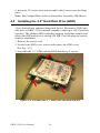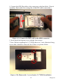
1
EBPC-3500
All-In-One, High Performance,
Embedded Box PC chassis for
3.5”Biscuit SBCs
User Manual
Copyright
The documentation and the software included with this product are copyrighted 2007 by Advantech Co., Ltd. All rights are reserved. Advantech
Co., Ltd. reserves the right to make improvements in the products
described in this manual at any time without notice. No part of this manual may be reproduced, copied, translated or transmitted in any form or
by any means without the prior written permission of Advantech Co., Ltd.
Information provided in this manual is intended to be accurate and reliable. However, Advantech Co., Ltd. assumes no responsibility for its use,
nor for any infringements of the rights of third parties, which may result
from its use.
Acknowledgements
Award is a trademark of Award Software International, Inc.
IBM, PC/AT, PS/2 and VGA are trademarks of International Business
Machines Corporation.
Intel and Pentium are trademarks of Intel Corporation.
Microsoft Windows and MS-DOS are registered trademarks of Microsoft
Corp.
RTL is a trademark of Realtek Semi-Conductor Co., Ltd.
All other product names or trademarks are properties of their respective
owners.
For more information on this and other Advantech products, please visit
our websites at: http://www.advantech.com
http://www.advantech.com.tw/products
Sub_Category.asp?Category_ID=1-TPYQ7&BU=ACG&PD=EC
For technical support and service, please visit our support website at:
http://support.advantech.com
This manual is for the EBPC-3500.
Part No. 2006E35000
Edition 1
Printed in Taiwan
August 2007
EBPC-3500 User Manual
ii
Product Warranty (2 years)
Advantech warrants to you, the original purchaser, that each of its products will be free from defects in materials and workmanship for two years
from the date of purchase.
This warranty does not apply to any products which have been repaired or
altered by persons other than repair personnel authorized by Advantech,
or which have been subject to misuse, abuse, accident or improper installation. Advantech assumes no liability under the terms of this warranty as
a consequence of such events.
Because of Advantech’s high quality-control standards and rigorous testing, most of our customers never need to use our repair service. If an
Advantech product is defective, it will be repaired or replaced at no
charge during the warranty period. For out-of-warranty repairs, you will
be billed according to the cost of replacement materials, service time and
freight. Please consult your dealer for more details.
If you think you have a defective product, follow these steps:
1.
2.
3.
4.
5.
Collect all the information about the problem encountered. (For
example, CPU speed, Advantech products used, other hardware
and software used, etc.) Note anything abnormal and list any
onscreen messages you get when the problem occurs.
Call your dealer and describe the problem. Please have your manual, product, and any helpful information readily available.
If your product is diagnosed as defective, obtain an RMA (return
merchandize authorization) number from your dealer. This allows
us to process your return more quickly.
Carefully pack the defective product, a fully-completed Repair and
Replacement Order Card and a photocopy proof of purchase date
(such as your sales receipt) in a shippable container. A product
returned without proof of the purchase date is not eligible for warranty service.
Write the RMA number visibly on the outside of the package and
ship it prepaid to your dealer.
iii
Declaration of Conformity
CE
This product has passed the CE test for environmental specifications
when shielded cables are used for external wiring. We recommend the use
of shielded cables. This kind of cable is available from Advantech. Please
contact your local supplier for ordering information.
This product has passed the CE test for environmental specifications. Test
conditions for passing included the equipment being operated within an
industrial enclosure. In order to protect the product from being damaged
by ESD (Electrostatic Discharge) and EMI leakage, we strongly recommend the use of CE-compliant industrial enclosure products.
FCC Class A
Note: This equipment has been tested and found to comply with the limits
for a Class A digital device, pursuant to part 15 of the FCC Rules. These
limits are designed to provide reasonable protection against harmful
interference when the equipment is operated in a commercial environment. This equipment generates, uses, and can radiate radio frequency
energy and, if not installed and used in accordance with the instruction
manual, may cause harmful interference to radio communications. Operation of this equipment in a residential area is likely to cause harmful interference in which case the user will be required to correct the interference
at his own expense.
EBPC-3500 User Manual
iv
Technical Support and Assistance
1.
2.
Visit the Advantech web site at www.advantech.com/support
where you can find the latest information about the product.
Contact your distributor, sales representative, or Advantech's customer service center for technical support if you need additional
assistance. Please have the following information ready before you
call:
– Product name and serial number
– Description of your peripheral attachments
– Description of your software (operating system, version, application software, etc.)
– A complete description of the problem
– The exact wording of any error messages
EBPC-3500 Models
EBPC-3500 Model List
EBPC-3500-75SE:
EBPC-3500-75CE:
EBPC-3500-80SE:
EBPC-3500-80CE:
EBPC-3500-81SE:
EBPC-3500-81CE:
EBPC for PCM-9375E
EBPC, chassis kit for PCM-9375E
EBPC for PCM-9380F
EBPC, chassis kit for PCM-9380F & PCM-9386F
EBPC for PCM-9381F
EBPC, chassis kit for PCM-9381F & PCM-9387F
v
Packing List
EBPC-3500 packing list
Description
Q'tys
EBPC-3500 Unit*
PS2 Keyboard/Mouse Cable
(P/N: 1700060202)
Driver and Utility CD for EBPC-3500 series V1.10
(P/N: 2066E35000)
2-P Phoenix to DC-Jack Power Cable
(P/N: 1700001394)
Mounting bracket
(P/N: 1960005758)
1
1
1
1
2
If any of these items are missing or damaged, contact your distributor or
sales representative immediately.
* Corresponding the ordering Part Number
EBPC-3500 User Manual
vi
Safety Instructions
1.
2.
3.
4.
5.
6.
7.
8.
9.
10.
11.
12.
13.
14.
15.
Please read these safety instructions carefully.
Please keep this User’s Manual for later reference.
Please disconnect this equipment from AC outlet before cleaning.
Don’t use liquid or sprayed detergent for cleaning. Use moisture
sheet or clothe for cleaning.
For pluggable equipment, the socket-outlet shall near the equipment and shall be easily accessible.
Please keep this equipment from humidity.
Lay this equipment on a reliable surface when install. A drop or
fall could cause injury.
Do not leave this equipment in an uncontrolled environment; storage temperatures above 60°C may damage the equipment.
The openings on the enclosure are for air convection hence protecting the equipment from overheating. DO NOT COVER THE
OPENINGS.
Make sure the voltage of the power source when connecting the
equipment to the power outlet.
Place the power cord such a way that people cannot step on it. Do
not place anything over the power cord. The power cord must be
rated for the product and for the voltage and current marked on the
product’s electrical ratings label. The voltage and current rating of
the cord should be greater than the voltage and current rating
marked on the product.
All cautions and warnings on the equipment should be noted.
If the equipment is not used for long time, disconnect the equipment from mains to avoid being damaged by transient over-voltage.
Never pour any liquid into ventilation openings; this could cause
fire or electrical shock.
Never open the equipment. For safety reasons, only qualified service personnel should open the equipment.
If one of the following situations arise, get the equipment checked
by service personnel:
a The Power cord or plug is damaged.
b Liquid has penetrated the equipment.
c The equipment has been exposed to moisture.
vii
d The equipment has not worked well or you can not get it work
according to user’s manual.
e The equipment has been dropped and damaged.
f
16.
The equipment has obvious signs of breakage.
CAUTION: THIS COMPUTER IS PROVIDED WITH A BATTERY-POWERED REAL-TIME CLOCK CIRCUIT. THERE IS A
DANGER OF EXPLOSION IF BATTERY IS INCORRECTLY
REPLACED. REPLACE ONLY WITH SAME OR EQUIVLENT
TYPE RECOMMENDED BY THE MANUFACTURE. DISCARD USED BATTERIES ACCORDING TO THE
MANUFACTURER’ S INSTRUCTIONS.
EBPC-3500 User Manual
viii
Wichtige Sicherheishinweise
1.
2.
3.
4.
5.
6.
7.
8.
9.
10.
11.
12.
13.
14.
Bitte lesen sie Sich diese Hinweise sorgfältig durch.
Heben Sie diese Anleitung für den späteren Gebrauch auf.
Vor jedem Reinigen ist das Gerät vom Stromnetz zu trennen. Verwenden Sie Keine Flüssig-oder Aerosolreiniger. Am besten dient
ein angefeuchtetes Tuch zur Reinigung.
Die NetzanschluBsteckdose soll nahe dem Gerät angebracht und
leicht zugänglich sein.
Das Gerät ist vor Feuchtigkeit zu schützen.
Bei der Aufstellung des Gerätes ist auf sicheren Stand zu achten.
Ein Kippen oder Fallen könnte Verletzungen hervorrufen.
Die Belüftungsöffnungen dienen zur Luftzirkulation die das Gerät
vor überhitzung schützt. Sorgen Sie dafür, daB diese Öffnungen
nicht abgedeckt werden.
Beachten Sie beim. AnschluB an das Stromnetz die AnschluBwerte.
Verlegen Sie die NetzanschluBleitung so, daB niemand darüber
fallen kann. Es sollte auch nichts auf der Leitung abgestellt werden.
Alle Hinweise und Warnungen die sich am Geräten befinden sind
zu beachten.
Wird das Gerät über einen längeren Zeitraum nicht benutzt, sollten
Sie es vom Stromnetz trennen. Somit wird im Falle einer Überspannung eine Beschädigung vermieden.
Durch die Lüftungsöffnungen dürfen niemals Gegenstände oder
Flüssigkeiten in das Gerät gelangen. Dies könnte einen Brand bzw.
elektrischen Schlag auslösen.
Öffnen Sie niemals das Gerät. Das Gerät darf aus Gründen der elektrischen Sicherheit nur von authorisiertem Servicepersonal geöffnet werden.
Wenn folgende Situationen auftreten ist das Gerät vom Stromnetz
zu trennen und von einer qualifizierten Servicestelle zu überprüfen:
– Netzkabel oder Netzstecker sind beschädigt.
– Flüssigkeit ist in das Gerät eingedrungen.
– Das Gerät war Feuchtigkeit ausgesetzt.
– Wenn das Gerät nicht der Bedienungsanleitung entsprechend
funktioniert oder Sie mit Hilfe dieser Anleitung keine Verbesserung erzielen.
ix
15.
16.
– Das Gerät ist gefallen und/oder das Gehäuse ist beschädigt.
– Wenn das Gerät deutliche Anzeichen eines Defektes aufweist.
VOSICHT: Explisionsgefahr bei unsachgemaben Austausch der
Batterie.Ersatz nur durch densellben order einem vom Hersteller
empfohlene-mahnlichen Typ. Entsorgung gebrauchter Batterien
navh Angaben des Herstellers.
ACHTUNG: Es besteht die Explosionsgefahr, falls die Batterie auf
nicht fach-männische Weise gewechselt wird. Verfangen Sie die
Batterie nur gleicher oder entsprechender Type, wie vom Hersteller
empfohlen. Entsorgen Sie Batterien nach Anweisung des Herstellers.
Der arbeitsplatzbezogene Schalldruckpegel nach DIN 45 635 Teil 1000
beträgt 70dB(A) oder weiger.
Haftungsausschluss: Die Bedienungsanleitungen wurden entsprechend
der IEC-704-1 erstellt. Advantech lehnt jegliche Verantwortung für die
Richtigkeit der in diesem Zusammenhang getätigten Aussagen ab.
EBPC-3500 User Manual
x
Safety Precaution - Static Electricity
Follow these simple precautions to protect yourself from harm and the
products from damage.
1.
2.
To avoid electrical shock, always disconnect the power from your
PC chassis before you work on it. Don't touch any components on
the CPU card or other cards while the PC is on.
Disconnect power before making any configuration changes. The
sudden rush of power as you connect a jumper or install a card may
damage sensitive electronic components.
xi
EBPC-3500 User Manual
xii
Contents
Chapter
1 Overview ...........................................................2
1.1
1.2
Introduction ....................................................................... 2
Features ............................................................................. 2
1.2.1
1.2.2
1.2.3
1.2.4
1.2.5
1.3
Hardware Specification ..................................................... 3
1.3.1
1.3.2
1.3.3
1.3.4
1.3.5
1.3.6
1.3.7
1.3.8
1.4
Universal, Comprehensive and Flexible I/O Expansion
Feature ............................................................................ 2
Wide range of DC Power Inputs, ATX Supported ......... 2
Compact, Robust Construction ....................................... 2
Highly Scalable Performance with Low Power Consumption .................................................................................. 3
Optimized Integration ..................................................... 3
Chassis Construction....................................................... 3
Universal I/O ports.......................................................... 3
System Biscuit SBC board support................................. 4
Drive Bay........................................................................ 6
Cooling System............................................................... 6
Power Supply.................................................................. 6
Mechanical Specification................................................ 6
Environmental Specification.......................................... 7
Chassis Dimension ............................................................ 8
Figure 1.1 Chassis Dimension ................................... 8
Chapter
2 Overview .........................................................10
2.1
Introduction of External I/O Connectors of EBPC-350075CE and EBPC-3500-75SE........................................... 10
Figure 2.1 Front metal face plate external I/O connectors of EBPC-3500-75CE and EBPC3500-75SE............................................ 10
Figure 2.2 Rear metal face plate I/O connectors of
EBPC-3500-75CE/EBPC-3500-75SE . 10
2.2
Introduction of External I/O Connectors of EBPC-350080CE and EBPC-3500-80SE........................................... 11
Figure 2.3 Front metal face plate external I/O connectors of EBPC-3500-80CE and EBPC3500-80SE............................................ 11
Figure 2.4 Rear metal face plate I/O connectors of
EBPC-3500-80CE/EBPC-3500-80SE . 11
2.3
Introduction of External I/O Connectors of EBPC-350081CE and EBPC-3500-81SE........................................... 12
Figure 2.5 Front metal face plate external I/O connectors of EBPC-3500-81CE and EBPCxiii
3500-81SE............................................ 12
Figure 2.6 Rear face plate I/O connectors for EBPC3500-81CE/EBPC-3500-81SE............. 12
Chapter
3 EBPC-3500 Internal Cable Arrangement and
Connection ......................................................14
3.1
System components placement of EBPC-3500............... 14
3.2
EUIO-350 Pin-headers/Connectors placement ............... 15
3.3
PCM-256 Pin-headers/Connectors placement ................ 15
3.4
PCM-257 Pin-headers/Connectors placement ................ 16
3.5
Internal cable corresponding connection table of EBPC3500-75CE and EBPC-3500-75SE ................................. 17
Figure 3.1 EBPC-3500 system layout inside ........... 14
Figure 3.2 EUIO-350 connectors ............................. 15
Figure 3.3 PCM-256 connectors .............................. 15
Figure 3.4
Table
3.6
3.2 EBPC-3500-80SE internal cables corresponding table ...................................... 20
Internal cable corresponding connection table of EBPC3500-81CE and EBPC-3500-81SE ................ 23
Table
Chapter
3.1 EBPC-3500-75SE internal cables corresponding table ...................................... 17
Internal cable corresponding connection table of EBPC3500-80CE and EBPC-3500-80SE ................ 20
Table
3.7
PCM-257 connectors ............................. 16
3.3 EBPC-3500-81SE internal cables corresponding table ...................................... 23
4 EBPC-3500 Hardware Installation...............28
4.1
4.2
Jumpers and Connectors.................................................. 28
EUIO-350 Jumper setting (JP1/JP2) for COM2 RS-232/
422/485............................................................................ 29
Table 4.1 COM2 RS-232/422/485 Jumpers ........... 29
Figure 4.1 EUIO-350 JP1 and JP2 jumper setting for
RS-232 ................................................. 29
Figure 4.2 EUIO-350 JP1 and JP2 jumper setting for
RS-422/RS-485 .................................... 30
4.3
Installing the DDR SDRAM Memory Module ............... 30
Figure 4.3 Remove the four screw of HDD cover ... 31
Figure 4.4 Plug the SDRAM into the RAM socket . 31
4.4
Inserting a Compact Flash Card ...................................... 32
Figure 4.5 Unscrew CF carrier from front plate ...... 32
Figure 4.6 Unscrew CF carrier from the front plate 33
Figure 4.7 Put the CF card into the CF carrier......... 33
4.5
Installing the 2.5" Hard Disk Drive (HDD) .................... 34
Figure 4.8 Assemble the 3.5”HDD onto the HDD
EBPC-3500 User Manual
xiv
bracket.................................................. 34
Figure 4.9 Connect the IDE cable to the HDD connector ......................................................... 35
Figure 4.10 Remove the 3 screws before 2.5” HDD installation ............................................... 35
4.6
Chapter
Connecting Power ........................................................... 36
5 System Disassembly Instruction ...................38
5.1
Introduction ..................................................................... 38
Figure
Figure
Figure
Figure
Figure
Figure
Figure
Unscrew top cover (right screw) ............ 38
Unscrew the top cover (left screw)......... 39
Unscrew the top cover (bottom screws) . 39
Remove the top cover. ............................ 40
Remove the top cover ............................. 40
Remove the FAN module ....................... 41
Unscrew the Hex-bolts of the front cover
(ex: EBPC-3500-80SE)........................ 41
Figure 5.8 Unscrew Hex-bolts on rear cover ........... 42
Figure 5.9 Remove fixing screws on the boards...... 42
5.2
5.1
5.2
5.3
5.4
5.5
5.6
5.7
Expansion IO plate assembly .......................................... 43
Figure 5.10 Remove the expansion IO plate on the front
panel ..................................................... 43
Figure 5.11 Remove the expansion IO plate on the rear
side ....................................................... 44
xv
EBPC-3500 User Manual
xvi
CHAPTER
1
Overview
This chapter gives background information on the EBPC-3500. It shows
you the EBPC-3500 overview and
specifications.
Sections include:
•
•
•
•
•
Introduction
Features
Hardware Specifications
Mechanical Specifications
Chassis Dimension
Chapter 1
Overview
1.1 Introduction
The EBPC-3500 series is a rugged and compact advanced Embedded Box
PC Chassis kit system. It is designed specifically for 3.5-inch Biscuit
Embedded SBC boards. With an easily customized design and front metal
I/O faceplate, the unit can be equipped with various 3.5-inch biscuit
boards.
1.2 Features
1.2.1
•
•
•
•
1.2.2
•
1.2.3
•
•
•
Universal, Comprehensive and Flexible I/O
Expansion Feature
Built-in universal I/O features that can carry all possible common
I/O functional feature ports and external access from the chassis.
Easy changeable and customizable front metal faceplate to suit various 3.5-inch biscuit SBC boards.
Reserved space to expand the I/O by PC-104, PCI-104 or MIO
interface card.
Two dummy I/O plates allow customization for expanding additional I/O feature ports.
Wide range of DC Power Inputs, ATX Supported
The EBPC-3500 series advanced Embedded PC system chassis
allows for a wide range of power input from DC 12 V ~ 24 V, and it
also supports ATX which offers system integrators the flexibility
and excellent power management for various embedded application
environments.
Compact, Robust Construction
Robust, heavy-duty metal cast construction.
Modularized design offers maximum space efficiency and good
Electromagnetic Compatibility.
A specially cushioned design that absorbs vibration of 2.5-inch
HDD to ensure maximum reliability.
EBPC-3500 User Manual
2
1.2.4
•
1.2.5
•
•
•
Highly Scalable Performance with Low Power
Consumption
Scalable Low Voltage and Ultra Low Voltage Pentium M class
processor system to bring high computing performance with low
power consumption.
Optimized Integration
Simple and modularized service-friendly design
Quick installation, easy expansion and maintenance
Long Life cycle support for protecting continuity to secure investment.
1.3 Hardware Specification
1.3.1
•
Chassis Construction
Construction
Rugged and Compact Advanced Embedded Wall-Mountable PC
system chassis.
•
Material
SECC, with painting.
1.3.2
•
Universal I/O ports
Parallel
1 * rear-access LPT port by a DB-25 female connector
•
GPIO
•
COM
1 * rear-access GPIO port by a DB-15 female connector
1 * rear-access COM port by a DB-9 male connector
•
LAN
1 * rear-access LAN port by a RJ-45 connector (EBPC-3500-75CE
and EBPC-3500-75SE only, others are reserved)
•
USB
2 * rear-access USB ports by a pair of double-stack mini-DIN connectors
•
Audio Line_In
1 * rear-access Line_In port by a Φ 3.5 mm audio jack connector
3
Chapter 1
•
Audio Mic_In
1 * rear-access Mic_In port by a Φ 3.5 mm audio jack Connector
•
Audio Line_Out
1 * rear-access Line_out port by a Φ 3.5 mm audio jack connector
•
LVDS
1 * rear-access LVDS Port by DB-26 female Connector
•
Backlight
1 * rear-access Backlight On/Off Control Port by DB-9 female
Connector
1.3.3
•
System Biscuit SBC board support
EBPC-3500-75CE
The EBPC-3500-75CE is the Embedded Box PC chassis kit specially designed for Advantech PCM-9375 series of Biscuit boards.
Please refer to the User Manual file of PCM-9375 Biscuit board
stored on the Driver and Utility CD Disk to learn more.
Please find the PDF file in the path of :
Driver Letter:
\Appendix\Usr Manu\PCM-9375_User_Manual_ed1.pdf from
Driver& Utility CD Disk.
•
EBPC-3500-75SE
EBPC-3500-75SE is an Embedded Box PC system with an Advantech PCM-9375E-J0A1E biscuit board inside. Please refer to the
User Manual of PCM-9375 biscuit board on the Driver and Utility
CD Disk to learn more.
Please find the PDF file in the path of :
Driver Letter:
\Appendix\Usr Manu\PCM-9375_User_Manual_ed1.pdf from
Driver& Utility CD Disk.
EBPC-3500 User Manual
4
•
EBPC-3500-80CE
EBPC-3500-80CE is the Embedded Box PC chassis kit specially
designed for Advantech’s PCM-9380 biscuit boards. Please refer to
the User Manual file of PCM-9380 biscuit board that stored on
Driver and Utility CD Disk to learn more.
Please find the PDF file in the path of :
Driver Letter:
\Appendix\Usr Manu\PCM-9380_User_Manual_ed3.pdf from
Driver& Utility CD Disk.
•
EBPC-3500-80SE
EBPC-3500-80SE is an Embedded Box PC system with Advantech
PCM-9380F-00A2E biscuit board inside. Please refer to the User
Manual file of PCM-9380F biscuit board on the Driver and Utility
CD Disk to learn more.
Please find the PDF file in the path of :
Driver Letter:
\Appendix\Usr Manu\PCM-9380_User_Manual_ed3.pdf from
Driver& Utility CD Disk.
•
EBPC-3500-81CE
EBPC-3500-81SE an Embedded Box PC chassis kit with Advantech’s PCM-9381series of Biscuit board. Please refer to the User
Manual file of PCM-9381 Biscuit board on the Driver and Utility
CD Disk to learn more.
Please find the PDF file in the path of :
Driver Letter:
\Appendix\Usr Manu\PCM-9381_User_Manual_ed2.pdf from
Driver& Utility CD Disk.
•
EBPC-3500-81SE
EBPC-3500-81SE is an Embedded Box PC system with Advantech’s PCM-9381F-00A2E Biscuit board inside. Please refer to the
User Manual file of PCM-9381 Biscuit board on the Driver and
Utility CD Disk to learn more.
Please find the PDF file in the path of :
Driver Letter:
\Appendix\Usr Manu\PCM-9381_User_Manual_ed2.pdf from
Driver& Utility CD Disk.
5
Chapter 1
1.3.4
•
Drive Bay
HDD Bay
1* 2.5-inch drive space
•
CF Socket
Optional support for 1* Compact Flash Socket from system SBC
board
1.3.5
•
Cooling System
System FAN
1* 40mm x 40mm x 20mm of VAPO-Bearing fan
•
Venting Hole
Located on top, left, right and rear for airflow convection.
1.3.6
•
Power Supply
Power Source
DC Input 12 VDC ~ 24 VDC
•
Power Input Connector
Front Access of 2-pole Phoenix type of DC power input connector;
support input power source of 12 VDC ~ 24 VDC .
•
Input Voltage (Typical)
12 VDC @ 4.5 A, 16 VDC @ 3.4 A, 19 VDC @ 2.9 A, 24 VDC @
2.3 A
•
Output Voltage
+5 VDC @ 7 A, +12 VDC @ 0.5 A, +5 VSB @ 1 A
•
•
Output Rating: 46W
Power ON/OFF
One Power On/Off switch, ATX supported.
1.3.7
•
Mechanical Specification
Mounting
Supports Table Mount and Wall Mount.
Built-in 1*Wall Mount kit in accessory.
•
System Indicator
1*Power on LED (Green)
1*HDD LED (Red)
EBPC-3500 User Manual
6
•
Weight
Net 1.6 Kg for EBPC-3500-75CE, EBPC-3500-80CE, EBPC3500-81CE
Net 2.0 Kg for EBPC-3500-75SE, EBPC-3500-80SE, EBPC3500-81SE
•
Dimension
Width: 230 mm / 9.05 inch
Height: 70 mm / 2.75 inch
Depth: 175 mm / 6.88 inch
1.3.8
•
•
•
Environmental Specification
Operation Temperature: 0° C ~ 45° C
Relative Humidity: 0% ~ 95% (none-condensing)
Vibration During Operation
1 Grms, IEC 60068-2-64, random, 5 ~ 500 Hz, 1 Oct./mm, 1hr/
axis. X, Y, Z three axes
•
Shock During Operation
20G, IEC 60068-2-27, half-sine, 11ms duration
•
EMC Certification
Design to meet CE/FCC Class A
•
EMS Certification
Design to meet UL Certification.
7
Chapter 1
1.4 Chassis Dimension
C OM
LAN
R ESET
P S /2
VG A
U S B
C F / C AR D
GN D
VC C
D C IN
1 2V ~2 4 V
-
+
Figure 1.1: Chassis Dimension
EBPC-3500 User Manual
8
CHAPTER
2
Overview
This chapter introduces EBPC-3500
external IO locations and internal
daughter boards connector locations.
Sections include the introductions of
Front and Rear External IO locations
for:
•
•
•
EBPC-3500-75CE, EBPC3500-75CE
EBPC-3500-80CE, EBPC3500-80SE
EBPC-3500-81CE, EBPC3500-81SE
Chapter 2
Overview
2.1 Introduction of External I/O Connectors of EBPC3500-75CE and EBPC-3500-75SE
The following two figures show the external I/O connectors on EBPC3500-75CE and EBPC-3500-75SE.
C OM 1
LAN PS/2
VGA
HDD
P WR
LINK AC T
RESET
DC IN
Figure 2.1: Front metal face plate external I/O connectors of EBPC-350075CE and EBPC-3500-75SE
USB3
USB4
PRINTER
COM 4
Reserve/LAN LINE IN
COM 3
PWR SW.
HDD
PWR
LVDS INVERTER
Reserve/DIO
COM 2
(RS232/422/485)
USB1
USB2
LINE OUT
MIC
Figure 2.2: Rear metal face plate I/O connectors of EBPC-3500-75CE/
EBPC-3500-75SE
EBPC-3500 User Manual
10
2.2 Introduction of External I/O Connectors of EBPC3500-80CE and EBPC-3500-80SE
The following two figures show the external I/O connectors on EBPC3500-80CE and EBPC-3500-80SE.
LAN PS/2
C OM 1
RESET
VGA
US B
CF/CARD
DC IN
Figure 2.3: Front metal face plate external I/O connectors of EBPC-350080CE and EBPC-3500-80SE
PRINTER
Reserve/LAN LINE IN
PWR SW.
HDD
PWR
LVDS
Back Light
Reserve/DIO
COM 2
(RS232/422/485)
USB1
USB2
LINE OUT
MIC
Figure 2.4: Rear metal face plate I/O connectors of EBPC-3500-80CE/
EBPC-3500-80SE
11
Chapter 2
2.3 Introduction of External I/O Connectors of EBPC3500-81CE and EBPC-3500-81SE
The following two figures show the external I/O connectors on EBPC3500-81CE and EBPC-3500-81SE.
C OM 1
LAN PS/2
VGA
US B
RESET
DC IN
Figure 2.5: Front metal face plate external I/O connectors of EBPC-350081CE and EBPC-3500-81SE
PRINTER
Reserve/LAN LINE IN
DVI
PWR SW.
HDD
PWR
LVDS INVERTER
Reserve/DIO
COM 2
(RS232/422/485)
USB1
USB2
LINE OUT
MIC
Figure 2.6: Rear face plate I/O connectors for EBPC-3500-81CE/EBPC3500-81SE
EBPC-3500 User Manual
12
CHAPTER
3
EBPC-3500 Internal
Cable Arrangement
and Connection
This chapter introduces EBPC-3500
internal cable connections for EBPC3500 series models of:
•
•
•
EBPC-3500-75CE, and EBPC3500-75SE
EBPC-3500-80CE, and EBPC3500-80SE
EBPC-3500-81CE, and EBPC3500-81SE
Chapter 3
EBPC-3500 Internal Cable
Arrangement and Connection
3.1 System components placement of EBPC-3500
Main Board
PCM-257
PCM-256
EUIO-350
Figure 3.1: EBPC-3500 system layout inside
EBPC-3500 User Manual
14
3.2 EUIO-350 Pin-headers/Connectors placement
CN12
CN1
CN9
CN10
CN2
Pin1
Pin1
CN5
CN6
Pin1
Pin1
Pin1 Pin1
Pin1
Figure 3.2: EUIO-350 connectors
3.3 PCM-256 Pin-headers/Connectors placement
CN1
CN5
Pin1
Pin1
Figure 3.3: PCM-256 connectors
15
Chapter 3
3.4 PCM-257 Pin-headers/Connectors placement
CN2
Pin1
Figure 3.4: PCM-257 connectors
EBPC-3500 User Manual
16
3.5 Internal cable corresponding connection table of
EBPC-3500-75CE and EBPC-3500-75SE
Table 3.1: EBPC-3500-75SE internal cables corresponding table
Part
Number
From
To
Picture
PCM- PCM- PCM- EUIO- Others
9375 256
257 350
1700002283 CN22
Audio
CN9
1700002276 CN15
USB 1,2
CN10
1700002172 CN13
USB 3,4
Rear
IO
faceplate
1700002285 CN16
COM
CN2
1700002287 CN17
LPT Port
CN1
17
Chapter 3
Table 3.1: EBPC-3500-75SE internal cables corresponding table
Part
Number
From
To
Picture
PCM- PCM- PCM- EUIO- Others
9375 256
257 350
1700002295 CN9
DIO
CN6
1700002286 CN2
Power
&
CN1
CN3
1700002281 CN11
HDD
Hard
Disk
1700002282 CN5
Inverter
CN5
1700002297 CN4
LVDS
CN1
EBPC-3500 User Manual
18
Table 3.1: EBPC-3500-75SE internal cables corresponding table
Part
Number
From
To
Picture
PCM- PCM- PCM- EUIO- Others
9375 256
257 350
1700001103 CN8
Switch
Switch
1750000399
FAN
FAN
19
Chapter 3
3.6 Internal cable corresponding connection table of
EBPC-3500-80CE and EBPC-3500-80SE
Table 3.2: EBPC-3500-80SE internal cables corresponding table
Part
Number
From
To
PCM- PCM- PCM- EUIO- Others
9380 256
257 350
1700002274 CN10
LED Status
CN5
1700002275 CN2
Audio
CN9
1700002276 CN5
USB 2,3
CN10
1700002277 CN8
COM2
CN2
1700002278 CN13
LPT Port
CN1
EBPC-3500 User Manual
20
Picture
Table 3.2: EBPC-3500-80SE internal cables corresponding table
Part
Number
From
To
Picture
PCM- PCM- PCM- EUIO- Others
9380 256
257 350
1700002279 CN7
DIO
CN6
1700002280 CN2
Power
CN3
1700002281 CN6
HDD
Hard
Disk
1700002288 CN17 CN5
Inverter
1700002289 CN1
LVDS
CN1
21
Chapter 3
Table 3.2: EBPC-3500-80SE internal cables corresponding table
Part
Number
From
To
Picture
PCM- PCM- PCM- EUIO- Others
9380 256
257 350
1700002294 CN16
Switch
Switch
1750000399
FAN
FAN
EBPC-3500 User Manual
22
3.7 Internal cable corresponding connection table of
EBPC-3500-81CE and EBPC-3500-81SE
Table 3.3: EBPC-3500-81SE internal cables corresponding table
Part
Number
From
To
Picture
PCM- PCM- PCM- EUIO- Others
9381 256
257 350
1700002274 CN10
LED Status
CN5
1700002275 CN2
Audio
CN9
1700002276 CN5
USB 2,3
CN10
1700002277 CN8
COM2
CN2
1700002278 CN13
LPT Port
CN1
23
Chapter 3
Table 3.3: EBPC-3500-81SE internal cables corresponding table
Part
Number
From
To
Picture
PCM- PCM- PCM- EUIO- Others
9381 256
257 350
1700000410 CN23
DVI
DVI
1700002280 CN2
Power
CN3
1700002281 CN6
HDD
Hard
Disk
1700002288 CN17 CN5
Inverter
1700002289 CN1
LVDS
CN1
EBPC-3500 User Manual
24
Table 3.3: EBPC-3500-81SE internal cables corresponding table
Part
Number
From
To
Picture
PCM- PCM- PCM- EUIO- Others
9381 256
257 350
1700002294 CN16
Switch
Switch
1750000399
FAN
FAN
25
Chapter 3
EBPC-3500 User Manual
26
CHAPTER
4
EBPC-3500 Hardware
Installation
This chapter introduces how to initialize the EBPC-3500.
Sections include:
•
•
•
•
•
Jumpers and Connectors
Installing the DDR SDRAM
Memory Module
Inserting a Compact Flash Card
Installing the 2.5" Hard Disk
Drive (HDD)
Connecting Power
Chapter 4
EBPC-3500 Hardware Installation
4.1 Jumpers and Connectors
The EBPC-3500 Embedded Box Computer consists of a PC-based computer that is housed in a metal chassis. Your HDD, SDRAM, are all
readily accessible by removing the accessed HDD cover from the bottom.
Any maintenance or hardware upgrades can be easily completed after
removing the top cover, front and rear face plate. If you are a system integrator and need to know how to completely disassemble the embedded
box computer, you can find more useful information in Chapter 5.
Warning! Do not remove any mechanical parts, such as
the top cover, bottom cover and front with rear face plate
until you have verified that no power is flowing within the
Embedded Box Computer. Power must be switched off
and the power cord must be unplugged. Every time you
service the Embedded Box Computer, you should be
aware of this.
The jumper settings are schematically depicted in this manual as follows:
A pair of needle-nose pliers may be helpful when working with jumpers.
If you have any doubts about the best hardware configuration for your
application, contact your local distributor or sales representative before
you make any changes.
EBPC-3500 User Manual
28
4.2 EUIO-350 Jumper setting (JP1/JP2) for COM2 RS232/422/485
The COM2 port located on EBPC-3500rear metal face plate can be configured to operate in RS-232, RS-422 or RS-485 mode. It is not only setting on the M/B but also the EUIO-350 need be setting up the Jumper JP1
and JP2 located on it. (Please see PCM user manual for M/B setting.)
Table 4.1: COM2 RS-232/422/485 Jumpers
Function
Setting
RS-232*
JP1 and JP2 (1-2 closed)
RS-422
JP1 and JP2 (2-3 closed)
RS-485
JP1 and JP2 (2-3 closed)
(*): means default setting of the jumper/function
Figure 4.1: EUIO-350 JP1 and JP2 jumper setting for RS-232
29
Chapter 4
Figure 4.2: EUIO-350 JP1 and JP2 jumper setting for RS-422/RS-485
4.3 Installing the DDR SDRAM Memory Module
EBPC-3500 provides one 200-pin SODIMM socket and supports 2.5 V
DDR SDRAM. You can install from 64 MB to 1 GB of DDR SDRAM
memory. The procedure for installing a DDR SDRAM SODIMM into the
EBPC-3500 is detailed below, please follow these steps carefully.
1. Remove the power cord.
2. Unscrew the HDD cover screws and remove the HDD cover.
EBPC-3500 User Manual
30
Figure 4.3: Remove the four screw of HDD cover
3. Plug a DDR SDRAM into the DDR SDRAM SODIMM socket on the
motherboard.
Figure 4.4: Plug the SDRAM into the RAM socket
4. Screw back the HDD cover with four screws.
31
Chapter 4
4.4 Inserting a Compact Flash Card
The procedure for installing a Compact Flash card into the EBPC-3500
(for models of EBPC-3500-80SE and EBPC-3500-80CE only) is detailed
below, please follow these steps carefully.
1. Remove the power cord.
2. Unscrew the two screws from the CF Door on the front plate.
Figure 4.5: Unscrew CF carrier from front plate
EBPC-3500 User Manual
32
3. Remove the CF carrier.
Figure 4.6: Unscrew CF carrier from the front plate
4. Remove the dummy CF card from the CF carrier.
5. Put the CF card into the CF carrier.
Figure 4.7: Put the CF card into the CF carrier
33
Chapter 4
6. Insert the CF carrier back and assemble with 2 screws onto the front
plate.
Note: The CompactFlash socket is allocated as Secondary IDE Master.
4.5 Installing the 2.5" Hard Disk Drive (HDD)
You can attach one enhanced Integrated Device Electronics (IDE) hard
disk drive to EBPC-3500's internal controller which uses a PCI local-bus
interface. The advanced IDE controller supports faster data transfer and
allows the IDE hard drive to exceed 528 MB. The following are instructions for installation:
1. Remove the power cord.
2. Unscrew the HDD cover screws and remove the HDD cover.
(See Fig. 4.3)*
3. Assemble the 3.5” HDD onto the HDD bracket by 4 screws.
Figure 4.8: Assemble the 3.5”HDD onto the HDD bracket
EBPC-3500 User Manual
34
4. Connect the IDE flat cable to the connector to the hard disk. (Treat it
carefully. Don’t make the wrong side of the IDE cable connection.)
Figure 4.9: Connect the IDE cable to the HDD connector
5. Screw back the bottom cover with the four screws.
* Note: Before installing the 2.5” HDD, there are 3 anti-vibration fixing
screws that should be removed first. Please see picture below.
Figure 4.10: Remove the 3 screws before 2.5” HDD installation
35
Chapter 4
4.6 Connecting Power
Connect the EBPC-3500 to a 12~24 VDC power source. The power
source can either be from a power adapter or an in-house power source.
EBPC-3500 User Manual
36
CHAPTER
5
System Disassembly
Instruction
This chapter shows how to disassemble EBPC-3500. It is easy for system
integrator to maintain.
Chapter 5
System Disassembly
Instruction
5.1 Introduction
If you want to completely disassemble the EBPC-3500 embedded box
computer, follow the step-by-step procedures below. Users should be
aware that Advantech Co., Ltd. takes no responsibility whatsoever for
any problems or damage caused by the user disassembly of the EBPC3500 embedded box computer. Make sure the power cord of the EBPC3500 embedded box computer is unplugged before you start disassembly.
The following procedures do not include the detailed disassembly procedures for the HDD, Compact Flash Disk and DRAM; all of which can be
found in Chapter 3.
1. Unscrew the top cover and remove it.
Figure 5.1: Unscrew top cover (right screw)
EBPC-3500 User Manual
38
Figure 5.2: Unscrew the top cover (left screw)
Figure 5.3: Unscrew the top cover (bottom screws)
39
Chapter 5
Figure 5.4: Remove the top cover.
2. Disconnect all the cables inside. (Besides the FAN module).
Figure 5.5: Remove the top cover
3. Remove the HDD module and CF card carrier. (Please see 4.3 ~ 4.5)
EBPC-3500 User Manual
40
4. Remove the FAN module.
Figure 5.6: Remove the FAN module
5. Unscrew the Hex-bolts of the front cover.
Figure 5.7: Unscrew the Hex-bolts of the front cover (ex: EBPC-350080SE)
41
Chapter 5
6. Unscrew the Hex-bolts of the rear cover.
Figure 5.8: Unscrew Hex-bolts on rear cover
7. Remove all the fixing screws of the boards.
Figure 5.9: Remove fixing screws on the boards
EBPC-3500 User Manual
42
5.2 Expansion IO plate assembly
The above-mentioned instructions are enough to guide a user to assemble
(disassemble) EBPC-3500. In the following steps are for the application
when user adding the MIO module (PC 104 module) or other expansions
and need to remove the front IO window and the rear IO window.
1. Remove the expansion IO plate on the front panel.
Figure 5.10: Remove the expansion IO plate on the front panel
43
Chapter 5
2. Remove the expansion IO plate on the rear side.
Figure 5.11: Remove the expansion IO plate on the rear side
EBPC-3500 User Manual
44