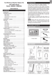
1
GB
Other features of the BAA913HG include backlight, extra-large
liquid crystal display (LCD) and a daily crescendo alarm with an
eight minute snooze function.
DIGITAL WEATHER FORECASTER
WITH IN-OUT
THERMO-HYGROMETER
No wire installation is required between the main and remote units
as the BAA913HG operates at 433 MHz.
MODEL : BAA913HG
USER’S MANUAL
MAIN FEATURES: MAIN UNIT
INTRODUCTION
Congratulations on your purchase of the BAA913HG Digital
Weather Forecaster with In-Out Thermo-Hygrometer.The
BAA913HG is an all-in-one weather forecasting device and clock.
B7
B6
B8
A
The BAA913HG, a weather forecasting device, has several weather
related functions. A main feature is that it takes and records
temperatures and humidities in more than one location. Using a
wireless remote thermo-hygro sensor, it can simultaneously monitor
temperatures and humidities in three remote locations. The unit
will show temperature and humidity trends as well as record
maximum and minimum temperature and humidity readings.
BAA913HG is able to receive and display readings from up to 3
remote sensors.
A1
A2
A3
A4
Hr
A5
As part of the weather forecasting function, the unit has a built-in
barometer that displays atmospheric pressure. Using animated
graphics, the unit displays atmospheric pressure trends and
displays forecasts as sunny, partly cloudy, rainy and snowy.
B3
B2
B4
B1
B5
1
913hg-e.p65
1
04/30/2002, 5:59 PM
GB
A.
B.
FRONT DISPLAY
The LCD is divided into five easy-to-read sections. Each
section has a specific purpose that relates to weather
forecasting, temperature, humidity, pressure and clock /
calendar / alarm functions.
CONTROL BUTTONS
B1. [CHANNEL
CHANNEL] BUTTON
CHANNEL
Displays the temperature and humidity readings of the indoor
or remote sensor
B2. [MEMORY
MEMORY] BUTTON
MEMORY
Displays minimum and maximum temperature and humidity
readings, and erases memory data
A1. WEATHER FORECAST WINDOW
- Graphically illustrates a weather forecast
- Indicates trends in atmospheric pressure
- Indicates when main unit battery is low
B3. [AL
AL / ] BUTTON
Displays the daily alarm time and Pre-alarm time period, or
changes the corresponding alarm time
A2. TEMPERATURE WINDOW
- Displays current, minimum or maximum indoor and remote
temperature
- Indicates temperature trend
B4. [MODE
MODE] BUTTON
MODE
Changes the display mode of the clock, and alters time/date
setting
A3. HUMIDITY WINDOW
- Displays current, minimum or maximum indoor and remote
humidity
- Indicates humidity trend
- Displays the Comfort Level
- Indicates when the battery of the remote sensor in display
is low
B5. [HISTORY
HISTORY] BUTTON
HISTORY
Displays the barometric reading for the last 24 hours, or
enter the altitude compensation setting
B6. [
] BAR
Activates the snooze function or turns on the backlight
B7 & B8. UP(+) DOWN(-) BUTTONS
Increases (+) or decreases (-) the value of a setting respectively
A4. ATMOSPHERIC PRESSURE
- Displays the current or historical (last 24 hours) barometric
reading
A5. TIME / DATE / ALARM WINDOW
- Displays the current time, date (day, month, and year), daily
alarm or Pre-alarm function
2
913hg-e.p65
2
04/30/2002, 5:59 PM
GB
C.
BACK PANEL
FEATURES: REMOTE THERMO-HYGRO
SENSOR
C1. BATTERY COMPARTMENT
Accommodates four UM-3 or “AA” size batteries
C2. mb / hPa - inHg SLIDE SWITCH
Selects between "mb / hPa" or "inHg" pressure unit display
C3. RESET SLOT
Resets the unit by returning all settings to their default values
C4. °C/°F SLIDE SWITCH
Selects between Centigrade (°C ) or Fahrenheit (°F) temperature
unit display
C5. RETRACTABLE TABLE STAND
Easy-open table stand with lock
3
913hg-e.p65
3
04/30/2002, 5:59 PM
GB
A.
TWO-LINE LCD
Displays the current temperature and humidity monitored by
the remote unit
B.
LED INDICATOR
Flashes when the remote unit transmits a reading
C.
°C/°F SLIDE SWITCH
Selects between Centigrade (°C) and Fahrenheit (°F)
D.
CHANNEL SLIDE SWITCH
Designates the remote unit Channel 1, Channel 2 or Channel 3
E.
RESET
Returns all settings to default values
F.
BATTERY COMPARTMENT
Accommodates two UM-4 or "AAA"-size batteries
G.
BATTERY DOOR
H.
WALL-MOUNT HOLDER
Supports the remote unit in wall-mounting
I.
REMOVABLE TABLE STAND
For standing the remote unit on a flat surface
BATTERY INSTALLATION: MAIN UNIT
1. Gently lift the tab on the battery compartment door.
2. Insert four UM-3 or “AA” size batteries.
3. Replace the battery compartment door.
BATTERY AND CHANNEL
INSTALLATION: REMOTE UNIT
BEFORE YOU BEGIN
The remote thermo-hygro sensor unit uses two (2) UM-4 or “AAA”
size batteries.
For best operation:
1. Insert batteries for the remote unit first. Then proceed with
inserting the batteries for the main unit.
2. Position the remote unit and the main unit within effective
transmission range. In usual circumstances, the effective
range is 30 meters.
3. Though the remote unit is weather proof, it should be placed
away form direct sunlight, rain or snow.
Follow these steps to install / replace batteries:
1. Remove the screws on the battery compartment.
2. Select the channel number on the [CHANNEL] slide switch.
3. Select the temperature display unit on the °C/°F slide switch.
4
913hg-e.p65
4
04/30/2002, 5:59 PM
GB
Press MODE again, the minute will flash. Again, use the
UP(+) or DOWN(-) button to change the minutes.
Note: When changes are made to this setting, the seconds will start
from zero.
Press MODE again, the calendar settings are displayed and the year
is flashing. Use the UP(+) or DOWN(-) button to change the year.
Press MODE again. The day (D) and month (M) symbols will flash.
The unit provides an option that allows either the day or the month
to be indicated first. Using the UP(+) or DOWN (-) button, select
whether the calendar reads as: Day/Month; or Month/Day.
4. Insert the batteries strictly according to the polarities shown
therein.
Press MODE button and the month will flash. Enter the appropriate
month using the UP(+) or DOWN(-) button.
5. Replace the battery compartment door and secure its screws.
Press MODE button and the day settings will flash. Enter the
appropriate day using the UP(+) or DOWN(-) button.
Replace the batteries when the low-battery indicator of the particular
channel lights up on the display. (Repeat the steps described in
section “BEFORE YOU BEGIN”)
Press MODE again and the language setting will flash. Use the
UP(+) or DOWN(-) button to select E for English, D for German, F
for French, I for Italian or S for Spanish.
Note :Once a channel is assigned to a remote unit, you can only
change it by removing the batteries or resetting the unit.
Press MODE to complete and exit the setting.
The weekday can be expressed as an abbreviation in five different
languages. The languages and their selected abbreviations for each
day of the week are shown in the language chart below.
HOW TO USE THE BACKLIGHT
Press [
for five seconds.
] bar once. The backlight will be activated
HOW TO SET THE CLOCK
Press MODE and hold for three seconds. The 12-hr value will flash.
Use the UP(+) or DOWN(-) buttons to make a selection between a
twenty-four hour display and a twelve hour display.
German
Press MODE again, the hour will flash. Use the UP(+) or DOWN
(-) button to enter the hours. Holding down either the up or down
position will increase or decrease the value rapidly.
5
913hg-e.p65
5
04/30/2002, 5:59 PM
GB
HOW TO SET AND ACTIVATE THE
ALARM
PRE-ALARM FUNCTION FOR CHANNEL
1 REMOTE SENSOR
To set the Alarm
AL / ] button to display the daily alarm time (the icon "AL"
Press [AL
will be displayed)
AL / ] and hold for three seconds, the value for the hour
Press [AL
will flash.
Press UP(+) or DOWN(-) buttons to make changes to the alarm
hour setting.
AL / ] and the minute will flash. Enter the value for
Press [AL
the minute by using UP(+) or DOWN(-) buttons.
AL / ] to exit.
Press [AL
The alarm is automatically activated. The ALARM ON icon [ ] is
visible and the alarm will activate at the specified time.
To deactivate the daily alarm function, press the DOWN(-) button
when the alarm time is displayed. The ALARM ON icon will
disappear and [ -:-- ] will be displated. To activate, press the UP (+)
button to display the alarm time again.
The alarm function also has a pre-alarm feature which can alert the
user before their preset alarm time if weather conditions changes.
This pre-alarm function applies to Channel 1 Remote Sensor only.
To enable this function, first activate the alarm function. Then enter
the Pre-Alarm mode by pressing the ALARM button twice. The
“Pre-Al” icon will be displayed.
Press and hold the ALARM button for 3 seconds to set the operating
time interval for this pre-alarm function. Use the UP or DOWN
button to select from the 4 time-intervals: 15, 30, 45 or 60 minutes.
Press the ALARM button to confirm and exit. The pre-alarm
function will be enabled automatically which is indicated by the
appearance of the [ ] symbol.
To disable this function, press the DOWN button in the Pre-Alarm
mode. The [ ] symbol will disappear and "-:--" will appear to
indicate disable of this function.
ALARM AND SNOOZE FUNCTION
The pre-alarm will operate during the selected time interval before
the daily alarm time. For example, if the daily alarm is set to go off
at 7:00 am and the pre-alarm operating time interval is set to 45
minutes, the pre-alarm will start to operate at 6:15 am (45 minutes
before 7:00 am).
When the daily alarm goes off alarm, the backlight will be on for
five seconds and the ALARM ON icon will flash.
The alarm function has a built in crescendo type alarm system.
Initially, the active alarm will have a gentle sound. The intensity
will increase in three stages. Without interruption, the unit will
alarm for two minutes.
To stop the alarm, press any button (expect MEMORY &
] bar is pressed, the
CHANNEL). However, if the [
SNOOZE function will be triggered. The alarm will stop and the
ALARM ON icon blinks for eight minutes. After that the alarm will
go off again. To deactivate the SNOOZE function, press the ALARM
button.
During the pre-alarm operating period, if the temperature recorded
at Channel 1 remote sensor falls to or below 2.0ºC, the pre-alarm
will be triggered. The Pre-Alarm icon will flash and the backlight
will be turned on for 5 seconds. An alarm sound will also go off for
2 minutes as that of the daily alarm and the snooze function will
also be activated if the [
] bar button is pressed.
6
913hg-e.p65
6
04/30/2002, 5:59 PM
GB
If that fails, check that the remote sensor is still in place. Make sure
the transmission is within range and the path is clear of obstacles
and interference.
Repeat this procedure whenever you find discrepancies between
the display on the main unit and the display on the remote sensor.
Note: The daily alarm will NOT function until the next day if the
pre-alarm has been triggered beforehand. Deactivation of the alarm
function will disable the pre-alarm feature automatically.
CHECKING INDOOR AND REMOTE
TEMPERATURES & HUMIDITIES
NOTE ON °C AND °F
To display the indoor and outdoor temperature and humidity
readings, press the CHANNEL button to toggle among the indoor,
Channel 1, 2 and 3 displays.
The outdoor temperature display on the main unit is dominated by
the selection on the °C/°F slide switch of the main unit. Whatever
the display unit of the remote sensor is, it will only apply to the
remote sensor itself and the temperature will be automatically
converted to the chosen one of the main unit.
The temperature can be shown in Centigrade (°C) or Fahrenheit
(°F). Select the appropriate reading by using the °C/°F slide switch
(located in the battery compartment). Slide the switch to °C for
Centigrade or °F for Fahrenheit.
MAXIMUM AND MINIMUM
TEMPERATURES & HUMIDITIES
This unit has an auto-scan function that can sequentially display
the indoor and remote readings.
The maximum and minimum recorded temperatures and humidities
will be automatically stored in memory. To display them, press
MEMORY. Press MEMORY again to alternate between the
maximum, minimum and current readings. The respective MAX or
MIN indicator will be displayed.
To clear the memory, press MEMORY and hold for three seconds.
The maximum and minimum recorded readings will be erased.
Subsequently, if you press MEMORY after the memory has been
erased, the maximum and minimum readings will have the same
values as the current ones.
To activate this function, press and hold the CHANNEL button for
3 seconds. To deactivate press the CHANNEL button again.
If the reading goes above or below the specified amounts, the
display will show a flashing “HHH” or “LLL”.
NOTE ON REMOTE READINGS
Once batteries are in place in the remote unit, it will start
transmitting samplings at 40 second intervals.
If no signals are received when the remote sensor display is selected,
“
” will be displayed. To force the main unit to search for
remote sensor signals, press MEMORY and CHANNEL
simultaneously.
7
913hg-e.p65
7
04/30/2002, 5:59 PM
GB
TEMPERATURE & HUMIDITY TREND
WEATHER FORECAST
The temperature and humidity trend indicator shows the trend of
temperatures and humidities collected at that particular sensor.
Three trends: rising, steady, and falling will be shown.
The unit is capable of detecting atmospheric pressure changes.
Based on collected data, it can predict the weather for the forthcoming
12 to 24 hours. The effective range covers an area of 30 to 50 km.
Arrow indicator
Temperature
Trend
Rising
Steady
Indicator
displays on
the unit
Falling
Forecast
Sunny Partly Cloudy
Cloudy
Raining
Snowy
Arrow indicator
Humidity Trend
Rising
Steady
NOTE:
1. The accuracy of a general pressure-based weather forecast is
about 70% to 75%.
Falling
2. The weather forecasts from this unit are predictions that cover
the next 12 to 24 hours. It may not necessarily reflect the current
situation.
ATMOSPHERIC PRESSURE
The atmospheric pressure indicator in the weather forecast window
uses arrows to indicate if the atmospheric pressure is increasing,
remaining stable, or decreasing.
3. The “Sunny” icon, as applies to night time, implies clear weather.
COMFORT LEVEL INDICATORS
The comfort level indicators COMFORT, WET or DRY will tell you
if the curent environment is comfortable, too wet or too dry.
Arrow indicator
Pressure Trend
Rising
Steady
The comfort indicator will appear on the display when the following
conditions are satisfied:
Falling
8
913hg-e.p65
8
04/30/2002, 5:59 PM
GB
Indicator
displays
on the unit
Shows that the
Current
Environment
The atmospheric pressure can be displayed in mb/hPa or inHg. The
pressure unit is selected on the atmospheric pressure slide switch
inside the battery compartment.
20°C to 25°C 40%RH(68°F to 77°F) 70%RH
Ideal range for
both relative
humidity and
temperature
If you want to check the pressure history for a particular hour
during the past 24 hours, press the [HISTORY] button. Each press
on the button will go back by an hour. Holding down the button
will increase the value rapidly.
-5°C -+ 50°C OVER(23°F - 122°F) 70%RH
Contains excess
moisture.
-5°C -+ 50°C Below
(23°F - 122°F) 40%RH
Contains
inadequate
moisture
Less than
20°C( 68°F)
or More than
25°C (77°F)
No comment
Temperature
Range
Humidity
Range
COMFORT
WET
DRY
No
Indicator
40%RH
to
70%RH
LOW BATTERY INDICATION
When it is time to replace batteries, the respective low battery
indicator [ ] will show up when the corresponding channel is
selected. The battery level of the main unit is shown on the Weather
Forecast Window when it is running low.
HOW TO WALL MOUNT OR USE THE
TABLE STAND (REMOTE UNIT)
The unit can be wall-mounted using its recessed screw holes or
place on a flat surface using the fold out table stand.
HOW TO CHECK THE BAROMETRIC
PRESSURE
Wall-mount
Table stand
The current and historical barometric pressure is shown on the
atmospheric pressure window.
For use at a higher altitudes, such as in the mountains, sea-level
barometric pressure applies. In this case, press and hold [HISTORY]
button to enter the altitude compensation setting mode. Use the UP
(+) or DOWN (-) button to select from –100 to 2500 meters
(whichever appropriate). Press [HISTORY] button to confirm and
exit.
9
913hg-e.p65
9
04/30/2002, 6:00 PM
GB
MAINTENANCE
HOW TO WALL MOUNT OR USE THE
TABLE STAND (MAIN UNIT)
When handled properly, this unit is engineered to give you years
of satisfactory service. Here are a few product care instructions:
The unit can be wall-mounted using its recessed screw holes or
placed on a flat surface using the collapsible table stand. Gently
pull the table stand from it’s collapsed position. Position the lock
to secure the stand.
Wall-mount
1. Do not immerse the unit in water. If the unit comes in contact
with water, dry it immediately with a soft lint-free cloth.
2. Do not clean the unit with abrasive or corrosive materials.
Abrasive cleaning agents may scratch the plastic parts and
corrode the electronic circuit.
Table stand
3. Do not subject the unit to excessive: force, shock, dust,
temperature, or humidity. Such treatment may result in
malfunction, a shorter electronic life span, damaged batteries, or
distorted parts.
4. Do not tamper with the unit’s internal components. Doing so
will terminate the unit’s warranty and may cause damage. The
unit contains no user-serviceable parts.
5. Only use new batteries as specified in this instruction manual.
Do not mix new and old batteries as the old batteries may leak.
6. Read this instruction manual thoroughly before operating the unit.
HOW TO RESET THE UNIT
SPECIFICATIONS
The RESET slot allows you to return all settings to factory values.
Accessing the slot is required only when the unit is not operating
in a favorable way such as in the rare case of a malfunction.
Temperature Measurement
Main unit
Indoor Temperature measurement
Proposed operating range
The RESET slot is located inside the battery compartment door. To
use the button,
1. Lift open the battery compartment door.
2. Place a blunt stylus into the slot and press.
Temperature resolution
: -5.0°C to +50.0°C
(23.0°F to 122.0°F)
: 0.1°C (0.2°F)
3. Replace the battery compartment door.
10
913hg-e.p65
10
04/30/2002, 6:00 PM
GB
Relative Humidity measurement
Measuring Range
- Power
Main unit
: 25% RH to 95% RH
at 25°C (77°F)
: use four (4) UM-3 or “AA”
1.5V batteries
Resolution
: 1% RH
Remote sensing unit
Remote unit
Temperature measurement
Proposed operating range
Temperature resolution
RF Transmission Frequency
No. of Remote unit
RF Transmission Range
Temperature sensing cycle
- Weight
: -20.0°C to +60.0°C
(-4.0°F to 140.0°F)
: 0.1°C (0.2°F)
: 433 MHz
: Up to 3 units
: 30 meters
: around 40 seconds
: 306 gm (without battery)
Remote sensing unit
: 63 gm (without battery)
Main unit
: 170(L) x 110(W) x 34(T) mm
Remote sensing unit
: 92(L) x 60(W) x 20(T) mm
CAUTION
— The content of this manual is subject to change
without further notice.
: 1% RH
— Due to printing limitation, the displays shown in
this manual may differ from the actual display.
: 795 to 1050mb / hPa
(23.48 to 31.01 inHg)
— The contents of this manual may not be reproduced
without the permission of the manufacturer.
Barometric Pressure measurement
Pressure measuring range
Main unit
- Dimensions
Relative Humidity measurement
Measuring Range
: 25 to 95%RH
at 25°C (77°F)
Resolution of Humidity
: use two (2) UM-4 or “AAA”
1.5V batteries
11
913hg-e.p65
11
04/30/2002, 6:00 PM
GB
VS-Villingen / Germany August 2001
EC-DECLARATION OF CONFORMITY
Gerhard Preis
This product contains the approved transmitter module TX 01 and
complies with the essential requirements of Article 3 of the R&TTE
1999/5/EC Directives, if used for its intended use and that the
following standard(s) has/have been applied:
R&TTE Representative of manufacturer
Efficient use of radio frequency spectrum
(Article 3.2 of the R&TTE Directive)
RTTE Compliant Countries :
applied standard(s)
All EC countries, Switzerland
And Norway N
EN 300 220-1(2,3):1997
Electromagnetic compatibility
(Article 3.1.b of the R&TTE Directive)
applied standard(s)
ETS 300 683:1997
Safety of information technology equipment
(Article 3.1.a of the R&TTE directive)
applied standard(s)
EN 60950:1997
Additional information:
The product therefore conforms with the Low Voltage Directive
73/23/EC, the EMC Directive 89/336/EC and R&TTE Directive
1999/5/EC (appendix II) and carries the respective CE marking.
12
913hg-e.p65
12
04/30/2002, 6:00 PM
CH