1
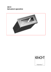
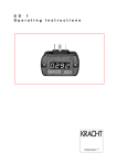
A S 8 Operating Instructions Volutronic 1. SAFETY 3 2. DESCRIPTION 4 3. CONNECTING THE AS8 5 3.1 Connecting the voltage supply 5 3.2 Connecting the volume counter 3.2.1 How is the flow rate measurement activated ? 3.2.2 How is the volume measurement activated ? 5 7 7 3.3 Connecting the relay contacts 8 3.4 Connecting the analogue outputs 9 3.5 Connecting the printer 3.5.1 Which data can be printed out ? 3.5.2 How is the data printed out ? 11 11 11 3.6 Parameterising via the serial interface 12 3.7 Error display 12 4. AS8 PROGRAMMING 13 4.1 Overview of the input values 14 4.2 What must be programmed when connecting a volume counter? 15 4.3 Which display parameters can be represented (DIP switches) ? 16 4.4 How is the display set ? 17 4.5 What must be programmed when connecting the relay outputs ? 18 4.6 What must be programmed when connecting the analogue output ? 19 5. TECHNICAL DATA 20 6. TYPE CODE 21 7. CONNECTIONS 22 8. SETTING THE SUPPLY VOLTAGE 23 9. DIMENSIONS 24 10. AS8 AS 19“ RACK UNIT 25 11. AS8 IN THE DESK-TOP HOUSING 26 PAGE 2 BAS8-0006-08.01-GB 1. Safety The safety notes included in these operating instructions are indicated by this ‘attention-getter’ symbol. If the text accompanying this symbol is not heeded, danger to personnel or equipment may result. F Other instructions, which are not safety warnings, but which give advice on optimum operation, are indicated by a hand. General safety instructions The electronic AS8 is constructed to the latest standards in technology. The AS8 should be operated only n in technically sound condition, n as instructed, n with awareness of the safety precautions, following these operating instructions. The AS8 must only be operated as an item of equipment installed in an internal area. The AS8 must only be operated in the prescribed condition. The stated limiting values (see also section on “Technical Data“) must, under no circumstances, be exceeded. Personnel engaged in the installation, operation and maintenance of the AS8 must be appropriately qualified. This qualification can be obtained by appropriate training or instruction. Such personnel must be familiar with the contents of these operating instructions. During all operations the relevant national regulations relating to safety precautions in the work place and where applicable, internal regulations of the operator must be observed, even if these are not detailed in these operating instructions. The AS8 must not be operated in hazardous areas, nor in areas where medical apparatus is in use, nor in areas which are expressly named in VDE 0411 Part 100. F F If the AS8 is used for the control of machines or sequential processes where damage to the machine or accident to operating personnel is possible as a consequence of failure or faulty operation of the AS8, then appropriate safety precautions must be implemented. In the case of variations (including those relating to operating behaviour), which prejudice safety, the AS8 must be switched off immediately. During installation work on the AS8, the power supply must always be disconnected. Installation work must only be carried out by appropriately qualified personnel. BAS8-0006-0801-GB Page 3 2. Description Measuring equipment devices in the AS8 series are four segment indicator units for flow rate and volumetric measurement. The units are usually operated in conjunction with KRACHT volume counters. However, other measuring systems with incremental signals can be connected. These may, for example, be oval wheel meters or angle of rotation sensors. The incremental input signals are filtered, converted and translated by the micro controller into the physical quantities of flow rate and volume. Two relays, an analogue output or an RS232 serial interface, are available for additional external processing. Programming and adjustment is achieved by means of three keys which are accessible on removal of the front cover. The integrated 24 V DC sensor supply enables direct connection to the volume counter. The measuring devices in the AS8 series are obtainable as built-in control panel devices, as desk-top units, or as 19“ rack-mounted units. The variety of characteristics and alternatives available make this compact unit always the first choice, particularly from the viewpoint of cost saving and when there is a special requirement to determine flow rate and volume. Manufacturers address: KRACHT GmbH Gewerbestraße 20 58791 Werdohl Tel. Fax 02392 / 935-0 02392 / 935209 PAGE 4 BAS8-0006-08.01-GB 3. Connecting the AS8 This section deals with the layout of the connections on the AS8. The electrical connections are made on a screw terminal strip. The connection layout for the desk-top unit and the 19” rack-mounted unit versions are covered in sections 10 and 11. 3.1 Connecting the voltage supply The AS8 is operated with an alternating voltage of 230 V / 115 V AC or direct voltage 12 / 24V DC. Please specify the kind of power supply when ordering. The exact type can be found in chapter 6.Type code. The connections for alternating-current voltage 120 / 230V AC : L N PE Terminal 1 Terminal 2 Terminal 3 The connections for direct voltage 12 / 24V DC : + GND PE Terminal 1 Terminal 2 Terminal 3 Fire prevention: The unit should be protected by an external fuse on the supply side. In accordance with VDE 0411, in the event of failure, 8A / 150 VA must not be exceeded. The recommended external fusing is 100 mA at a supply voltage of 115 and 230 Volt. 3.2 Connecting the volume counter The ASR16 is preferably operated in conjunction with KRACHT volume counters. However, other measuring systems with incremental signals can be connected. These can be, for example, oval wheel meters or angle of rotation sensors. Sensor supply The sensor supply is not short circuit proof. F The sensor supply is connected to connections 8 and 9. However, the sensor supply must not be used for the supply of unearthed inductances or capacitive loads. BAS8-0006-0801-GB Page 5 Voltage Terminal 8 +24 VDC +/- 20 % Terminal 9 0 V Signal inputs Ripple load dependent Maximum permissible current 50 mA Measuring systems with incremental signals provide two square wave pulses. The square wave pulses are displaced from one another by 90°. It is therefore possible to detect the direction. This is referred to as a two channel layout. If a measuring system with one square wave output is available, it is referred to as a single channel layout. In this case direction detection is not available. F Single channel or two channel connection must be set on the AS8. The settings required are made under menu reference „08“ at the “meter input” position (see 4.1 overview of the input values). Connection of the signal inputs is made on terminals 10 and 11. Connection terminal 11 is not used on the single channel layout. Counting input Channel 1 Channel 2 Terminal 10 Terminal 11 The measurement parameters of flow rate and volume are derived from the square wave signals. F The terms volume measurement and flow rate measurement are often interchanged, however, they are two completely different measurement parameters. F The indicator, the relay and the analogue output can be switched between flow rate measurement and volume measurement, as desired. This is achieved in the programming of the AS8 under the menü reference „7“. A „0“ is set for flow rate measurement and a „1“ for volume measurement (see 4.1 Overview of the input values). PAGE 6 BAS8-0006-08.01-GB 3.2.1 How is the flow rate measurement activated ? As soon as a medium flows through the volume counter a flow rate indication appears. No special action is required. The instantaneous flow rate is indicated, as a rule in litres per minute. F The AS8 must be adjusted to the actual volume counter that is connected. The procedure is given in section 4.2 What must be programmed when connecting a volume counter? 3.2.2 How is the volume measurement activated ? By volumetric measurement is implied the summation of the amount of a medium which has flowed through a volume counter. As a rule the indication is in litres. F The summation commences when the summation enable is switched. The enable input is connected to terminal 12. F If there is a voltage of 24 V at the enable input, summation of the volume commences. The measured values on the display change. If there is a voltage of 0 V at the enable input, summation of the volume is stopped. The measured values on the display do not change. When the voltage at the enable input is changed from 0 V to 24 V the summation is reset to zero. The determination of the volume starts again. F The AS8 must be set for the particular volume counter that is connected The procedure is given in section 4.2 What must be programmed when connecting a volume counter? BAS8-0006-0801-GB Page 7 3.3 Connecting the relay contacts The AS8 has two relay contacts. The relays are designed as potential-free contacts. That is to say, the user must input the potential at the base terminal. The relays are provided with normally-open contacts. The switching voltage is 24 V, maximum switching current is 1A. Voltages greater than 48 V must not be switched on any account. Relay K0 K1 Contact ( Signal ) Common terminal (Base) Terminal 5 Terminal 6 Terminal 7 Terminal 7 How do the relays operate ? The function of the relays can be set as required, i.e. each relay can be allocated to the flow rate or volume measurement parameters. F The relays can be set as required to flow rate measurement or volume measurement. Thhis is achieved in the programming of the AS8 under the menu reference „7“ at the „Relais 1“ or „Relais 2“ position. A „0“ sets the flow rate position, a „1“ sets the volume measurement (see 4.1 Overview of the input values). An on and an off switching value can be programmed for each relay. The relay switches when the switch-on value is exceeded. When the switch-off value is undershot, the relay drops out again. The relays can be programmed as normallyopen or normally-closed. F PAGE 8 The programming of the switch-on and switch-off values is given in section 4.5 What must be programmed when connecting the relay outputs?. BAS8-0006-08.01-GB 3.4 Connecting the analogue outputs The AS8 operates via an analogue output or a serial interface. The appropriate adjustment is achieved within the device, by means of jumpers. The jumper settings for current output and voltage output are shown in the accompanying figures. Current output setting JP2 JP1 15 14 13 12 11 10 9 8 7 JP3 JP5 P3 JP4 F P2 P1 The strength can be set on P1 and the offset on P2. Voltage output setting JP2 JP1 JP3 JP5 P3 JP4 F P2 P1 15 14 13 12 11 10 9 8 7 The strength can be set on P3 and the offset on P2. In accordance with the software, the settings +/-10 Volt, 0-10 Volt and 210 Volt and +/-20 mA, 0-20 mA and 4-20 mA are available for signal selection. The selection is carried out by programming the AS8 under menu reference “8“ at the “Analogue output“ position. The functions are set using “0“ or “1“ (see 4.1 Overview of the input values). Analogue output PLUS Minus Terminal 14 Terminal 15 How does the analogue output function ? BAS8-0006-0801-GB Page 9 The function of the analogue output can be freely selected, i.e. it can be assigned to the measurement parameters of flow rate or volume. F The display, the relay and the analogue output can be switched to flow rate measurement or volume measurement , as required. This selection takes place when programming the AS8 under menu reference “7” at the “analogue output” position. A “0” sets flow rate measurement and a “1” sets volume measurement (see 4.1 Overview of the input values). A maximum value can be programmed for the analogue output. The maximum value corresponds to an output of 10 V and 20 mA. F PAGE 10 The details of programming the maximum value are given in section 4.6 What must be programmed when connecting the analogue output ? BAS8-0006-08.01-GB 3.5 Connecting the printer The AS8 makes use of a serial interface having an RS232 layout. The choice between analogue output or serial interface is made by means of a jumper inside the unit. Setting for the serial interface JP2 JP1 JP3 JP5 P3 JP4 P2 P1 15 14 13 12 11 10 9 8 7 The RS232 has the fixed setting: 9600 baud, 8 bit, No parity, XON, XOFF. There is no hardware handshake. RS 232 Transmit data TXD Receive data RXD Functional earth GND Terminal 14 Terminal 15 Terminal 9 The interface can be operated as a printer interface and for “parameterising” the AS8. There is no switch-over between the operating modes. In the printer interface operating mode, the selected data is output as ASCII characters via the serial interface. The instantaneously displayed value is printed out each second, followed by a CR LF. Example: Displated value Printout ASCII String 3.500 + 3.500 2 B 33 2E 35 30 30 0D 0A 3.5.1 Which data can be printed out ? The currently displayed value is printed out. 3.5.2 How is the data printed out ? A printout is triggered via a digital input. The values are transferred to the serial interface in a per second sequence. The printer drive is switched-on on the application of a voltage of 24 V at the enable input (terminal 13). F BAS8-0006-0801-GB Page 11 3.6 Parameterising via the serial interface A PC or a PLC is connected to the AS8 via the serial interface. The PC or PLC can change specific AS8 parameters by means of an ASCII character string. The unit distinguishes between the different values through an identifying letter. No protocol is used. The character string is received complete as an ASCII string and converted on acceptance. ASCII strings can only be received one after the other. If a faulty string is received, an ERROR string is sent. Example: Identifying letter Input value Pulse size volume counter Max.value analogue output Damping - digital filter ‘Pull-in’ value Relay 1 ‘Drop-out’ value Relay 1 ‘Pull-in’ value Relay 2 ‘Drop-out’ value Relay 2 ERROR String (Echo) A B C D E F G String ASCII STRING A0.040 B3.500 C9999. D0.000 E1.000 F1.500 G3.000 ERROR0 41 30 2E 30 34 30 42 33 2E 35 30 30 43 39 39 39 39 2E 44 30 2E 30 30 30 45 31 2E 30 30 30 46 31 2E 35 30 30 47 33 2E 30 30 30 45 62 62 5F 62 30 3.7 Error display On two channel volume counters it is possible to monitor the correct pulse sequence on the channels. Faulty pulses are not counted and thus do not change the volume measurement. If an error is established by the AS8, the character sequence “FAUL“ appears in the display. F PAGE 12 The error display can also be completely isolated. This is carried out under the menu reference “08“ at the “Error display“ position. The error display is enabled with a “0” and blocked with a “1” (see 4.1 Overview of the input values). BAS8-0006-08.01-GB 4. AS8 programming Each time the AS8 is to be operated, it is necessary to adapt the unit to the volume counter that is connected. Input procedure: The input procedure is the same for all input values and is therefore described once only. Programming is carried out by means of three keys which are accessible on removing the front cover. With the keyboard version /F the configuration can be made with keys on front panel.The positions of these three keys is shown below. DIP- Switches F1 F2 F3 Start input operation “F1“ is depressed for approx. four seconds to start the input operation. The first three segments are switched dark, segments four and five display the menu reference number ”00“. Release “F1“. Change menu reference By briefly pressing “F1“ the menu reference numbers “00” to “08” can be displayed in sequence. An input value is concealed behind each menu reference number. To display the input value, press “F3” briefly. A four digit input value appears. Change input value The point marks the digit which can be changed by actuating “F3”. The point can be moved by actuating “F2“. After setting the numerical values the point must be placed at the correct position. On actuating “F1”, the display reverts to the menu-reference level. The menu reference “00” is displayed again. Stop input value To exit the input operation, depress “F1” again for approx. four seconds. BAS8-0006-0801-GB Page 13 4.1 Overview of the input values The values which are required to be set can be inserted in the column labelled “Input value-User”. Menu Reference 00 01 02 03 04 05 06 07 Standard setting 0.040 4.000 0001. 9999. 9999. 9999. 9999. 0000 Input value User Function Pulse volume of volume counter Maximum value Analogue output Damping Digital filter “Pull-in” value Relay 1 “Drop-out” value Relay 1 “Pull-in” value Relay 2 “Drop-out” value Relay 2 Display : 0 = Flow rate / 1 = Volume Analogue output: 0 = Flow rate / 1 = Volume Relay 1 : 0 = Flow rate / 1 = Volume Relay 2 : 0 = Flow rate / 1 = Volume 08 0000 Counter input Error display Analogue output Analogue output : 0 = 2-channels / 1 = 1 channel : 0 = Activated / 1 = Blocked : 0 = Bipolar / 1 = Unipolar : 0 = 0-20mA / 1 = 4-20 mA If the on and off values for the relays are set at 9999. , then the relays are isolated. PAGE 14 BAS8-0006-08.01-GB 4.2 What must be programmed when connecting a volume counter? The AS8 Microcontroller is set-up for the connected volume counter. This is carried out under menu reference “00 - pulse volume volume counter” and under menu reference “08” at the position “counter input”. The pulse volumes for KRACHT Volume counters can be obtained from the Table. The “X” characters in the “Input value Menu reference 08“ column are of no significance in setting the volume counter. Designation Material Input value Menu reference 00 Input value Menu reference 08 VC 0,025 Sp. Gr./ Iron* 0,025 cm3 XXX0 2 channels VC 0,04 Sp. Gr./ Iron 0.040 cm3 XXX0 2 channels VC 0,2 Sp. Gr./ Iron 0.245 cm 3 XXX0 2 channels 3 VC 1 Sp. Gr./ Iron 1.036 cm XXX0 2 channels VC 3 Sp. Gr./ Iron 3.000 cm³ XXX0 2 channels VC 5 Sp. Gr./ Iron 5.222 cm3 XXX0 2 channels Sp. Gr./ Iron 3 10.48 cm XXX0 2 channels VCA0,2VCN0,2 Aluminium 0.200 cm³ XXX1 1 channel VCA 2 Aluminium 2.000 cm3 XXX1 1 channel VC 0,2 .JR High grd. St.* 0.200 cm³ (old) XXX0 2 channels VC 1 .JR High grd. St. 1.000 cm3 (old) XXX0 2 channels VC 5 .JR High grd. St. 5.000 cm3 (old) XXX0 2 channels High grd. St. 0.100 cm3 (old) XXX0 2 channels VC 10 VCL 0,1 PA(B) * Sp. Gr. Iron = Spheroidal graphite iron * High grd. St. = High grade steel Example: A VC0.04 volume counter is connected. The pulse volume is 0.040 cm3. The VC 0.04 Volume counter has a 2 channel layout. n The value 0.040 is entered under menu reference “00“. n A “0” is entered under menu reference “08” at the position designated “counter input”. BAS8-0006-0801-GB Page 15 4.3 Which display parameters can be represented (DIP switches) ? The physical parameters “l/h“, “l/m“, “l/s“ and “Usgal/h“, “Usgal/m“, “Usgal/s“ can be set as display units. Switching between the display parameters is achieved using the DIP switches. The DIP switches are located behind the front cover. Setting the volume: SW 1 OFF ON Function Indication in LITRES Indication in USGAL Factory setting X Setting the time base: SW 2 OFF OFF ON ON SW 3 OFF ON OFF ON Function Minutes Minutes Hours Seconds Factory setting X In principle, parameters such as Millilitres, Grams, Millimeters, Meters and Kilograms can also be displayed. These can be set via the pulse volume. Example: Volume counter connection VC1 Unit Pulse factor Conversion Volume counter factor Millilitres Grams Kilograms 1.036 1.036 1.036 x x x 1000 1000 1 Density medium Pulse volume Menu reference 00 x 1.000 x 1.230 x 1.230 = = = 1036 1274 1.274 Units of length are converted in the same way. Example: Measurement of the speed or position of a cylinder. VC1mounted on the piston. Piston diameter = 10 cm => A = 10 cm x 10 cm x PI/ 4 = 78.54 cm2 Factor VC Factor for each pulse = -------------Area A Unit Millimetres Metres PAGE 16 Factor for each pulse 0.1319 0.1319 1.036 cm3 = --------------- = 0.01319 cm = 0.1319 mm 78.54 cm2 ========= Conversion factor x 1000 x 1 pulse volume Menu reference 00 = 131.9 = 0.132 BAS8-0006-08.01-GB 4.4 How is the display set ? The display can be set for flow rate measurement or volume measurement. Flow rate measurement A “0” is entered at the position designated “Display” under the menu reference “07” (see 4.1 Overview of the input values). Filter function The measuring principle applied to the AS8 is that of ‘period of oscillation’. When the flow rate is subject to severe fluctuation, the digital filter provides a smoothing effect to steady the indication. A digital filter can be activated under the menu reference “02”.. The higher the input value the greater the filter effect. Programmed value 0000: Programmed value 9999: no filter effect maximum filter effect Volume measurement A “1” is entered at the position designated “Display”, under the menu reference “07” (see 4.1 Overview of the input values). The pulses of the volume counter are counted, converted using the pulse volume and displayed. BAS8-0006-0801-GB Page 17 4.5 What must be programmed when connecting the relay outputs ? The relay function is selectable. A relay can be allocated to flow rate or volume measurement. Flow rate measurement A “0” is inserted under the menu reference “07”. This takes place at the position designated “Relay 1” or “Relay 2” (see 4.1 Overview of the input values). Volumetric measurement A “1” is inserted under the menu reference “07”. This takes place at the position designated “Relay 1” or “Relay 2” (see 4.1 Overview of the input values). Switch functions For Relay 1, programming takes place under the menu references “03” and “04”, for Relay 2 under the menu references “05” and “06” (see 4.1 Overview of the input values). The following switch functions can be obtained:: Normally-open function On reaching the switch-on value the contact is closed. Example: Switch-on value (pull-in): 2,500 Switch-off value (drop-out): 9999 The relay contact is switched when the switch-on value is exceeded. The switch-off value of 9999 has the consequence, that only the switch-on value is evaluated. The relay is not disconnected when the switch-off value is reached. Normally-closed function On reaching the switch-off value the contact is opened. Example: Switch-on value: 0.000 Switch-off value: 3,000 The relay contact is switched so long as the switch-off value is not reached. The switch-on value of 0.000 has the consequence, that only the switch-off value is evaluated. The relay is not switched-off if the switch-on value is reached. Window function Example: Switch-on value: 2,500 Switch-off value: 3,000 The relay contact is switched when the switch-on value is reached. If the switch-off value is exceeded, the relay opens again. PAGE 18 BAS8-0006-08.01-GB 4.6 What must be programmed when connecting the analogue output ? The function of the analogue output is selectable. The analogue output can be assigned to flow rate or volume measurement. Flow rate measurement A “0” is entered under menu reference “7”. This takes place at the position designated “Analogue output” (see 4.1 Overview of the input values). Volume measurement A “1” is entered under menu reference “7”. This takes place at the position designated “Analogue output” (see 4.1 Overview of the input values). Signal selection Menu reference 08 Analogue output 00XX +/- 20 mA or +/- 10 Volt 01XX 0 - 20 mA or 0 - 10 Volt 10XX +/- 20 mA or +/- 10 Volt 11XX 4 - 20 mA or 2 - 10 Volt The digits identified with an “X” in the Menu reference “08” column are of no significance to the setting procedure. The maximum value is entered under the menu reference “01”, maximum analogue output, corresponding to an output of 10 V or 20 mA. Example: Maximum analogue output value: 4,000 [ Litres / minute ] The flow rate is 4,000 Litres/minute, so 10 Volt or 20 mA are output. If the flow rate is 0,000 Litres/minute, then 0 Volt or 0 mA is output. BAS8-0006-0801-GB Page 19 5. Technical Data Processor Power pack Supply Power consumption Sensor supply General data PIC 17C42 230 V AC, +6% ... -10% / 50-60 Hz, optional 115 V AC ca. 3.5 W 24 V DC +/- 20%, 50 mA Display Principle : 7 Segment LED, 13.2 mm, red Display :0.000 ... 9999 with floating point overrun ( >9999 ) : display 9999 overrun (<-9999 ) : display -9999 Status indication : LED K1 and K2 for relays 1 and 2 Control keys Housing Front frame Installed depth Panel cut-out Protection class (DIN 40050) Weight Connections Relay contacts Digital inputs Three keys behind the front cover, optional: keys on front panel Control panel housing in plastic 96x48 mm, DIN 43700 ca. 122 mm with terminal strip 92x45 mm, Tol +0.8 x +0.6 mm IP 54 with appropriate control panel installation ca. 0.4 kg 15 pole screw terminal strip each 1 N.O., 24 Volt / 1 A, typ. operating time 6 ms Input impedance Input amplitude Operating time Analogue outputs >= 7500 Ohm low <= 9 Volt, high >= 12 Volt typ. 1 ms Set as voltage or current output via jumpers Voltage output +/- 10 Volt, 0 - 10 Volt, 2 - 10 Volt / load >= 1 kOhm, Resolution 10 bit, short-circuit proof +/- 20 mA, 0 - 20 mA, 4 - 20 mA / load <= 250 Ohm, Resolution 10 bit, short-circuit proof Current output Volume counter inputs Input impedance Input amplitude >= 7500 Ohm low <= 9 Volt, high >=12 Volt Measuring principle, flow rate Maximum input frequency Measuring range, totalisator Serial interfaces Period of oscillation measurement (rising edge) 1Hz ... 2500 Hz 2 x 10⁹ pulses Screened data cable recommended RS 232 Input voltage Input current Output current Setting Cable Ambient conditions Cable length <= 15 m max. +/-30 V typ. +/- 3 mA at +/- 9 V input voltage typ. +/- 3 mA 9600 baud, 8 bit, no parity, 1 stop bit Screened data cable recommended Operating temperature Storage temperature 0 C to + 60 °C -25 °C to +85 °C PAGE 20 BAS8-0006-08.01-GB 6. Type code Example : AS8 - U - 230 / .../ .... F keys on front panel Identification for special programs DOS ZM RP PUR V2F V2C A2F D2F FM20 Dosing 230 120 12 24 230 VAC 50/60 Hz U I RS Voltage output +/- 10 Volt Cylinder stroke measurement Flow control loop Ratio control loop Flow rate and ratio measurement Volume ratio measurement Sum measurement Difference measurement Flow rate measurement switchable for all KRACHT volume counters Without Standard Flow rate or volumetricmeasurement specification BAS8-0006-0801-GB 120 VAC 50/60 Hz 12 VDC 24 VDC Current output +/- 20 mA Serial interface RS232 Page 21 7. Connections The electrical connections are made on plugable screw terminals. Stranded connections on the basis of the prevention of accidental contact in accordance with VDE 0411 Part 100 only by means of connector sleeves with insulating material caps. Non-factory wired connections should not be otherwise connected. It is recommended that all signal connection leads are screened and the screening earthed on both sides, in order to avoid HF interference. The signal connection leads should not be combined in the same cable assembly as mains cables, motor cables, etc. JP2 JP1 15 14 13 12 11 10 JP3 JP5 P3 JP4 Volt Printer interface or Analogue output Enable printer Enable summation Channel 2 Channel 1 9 P2 P1 0 Sensor F1 100 mA Fuse TRANSFORMER or DC/DC converter 8 7 6 5 4 3 2 24 Volt Relay contact base Relay contact 2 Relay contact 1 Screen 1 12VDC, 24VDC PE Power Supply or 120VAC, 230VAC Printer interface 15 14 13 12 11 10 9 PAGE 22 Analogue output RXD TXD 15 14 Analogue output (-) Analogue output (+) GND BAS8-0006-08.01-GB 8. Setting the supply voltage Supply voltage 230 V AC/ 50-60 Hz View of circuit board from below Close solder jumper 1 to 3 3 4 1 2 supply voltage 115 V AC/ 50-60 Hz View of circuit board from below Close solder bridges 1 to 2 and 3 to 4 3 4 1 2 BAS8-0006-0801-GB Page 23 9. Dimensions PAGE 24 BAS8-0006-08.01-GB 10. AS8 as 19“ Rack Unit The AS8 is built into a 3HE 25TE 19” front plate. All the connections for the AS8 are wired on a Eurocard and are available on a 32 pin contact strip for further connection. AS8 wiring on the contact strip: Contact PIN AS8 terminal ac2 ac4 ac6 ac8 ac10 ac12 ac14 ac16 ac18 ac20 ac22 ac24 ac26 ac28 ac30 ac32 8 10 11 12 13 14 15 5 6 24 Volt sensor supply Channel 1 Channel 2 Enable summation Enable printer TXD / Analogue output (+) RXD / Analogue output (-) Relay contact 1 Relay contact 2 2 1 3 N L PE 7 9 Relay contact base 0 Volt View: BAS8-0006-0801-GB Page 25 11. AS8 in the Desk-top Housing The desk-top housing is available with analogue output or serial interface. View: PAGE 26 BAS8-0006-08.01-GB Connections with RS232 serial interface: Connections with analogue output: BAS8-0006-0801-GB Page 27