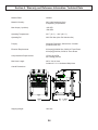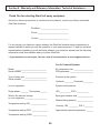
1
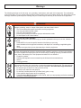
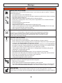
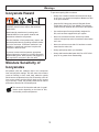
MH VR
USER MANUAL
Dispensing System
For use with non-flammable foam and polyurea.
Not for use in explosive atmospheres.
Maximum working fluid pressure:
3200 psi. (22.06 MPa, 217.73 bar)
Important Safety Instructions
Read all warnings and instructions in
this manual. Save these instructions.
Table Of Contents
Section 1 Installation
Warnings ...........................................................................................................................................................
Introduction ........................................................................................................................................................ Standard Equipment ..........................................................................................................................................
Equipment Assembly ..........................................................................................................................................
1
5
6
7
Section 2 Operation
Start-up Instructions ........................................................................................................................................... Shut–down Instructions ...................................................................................................................................... Daily Start-Up Instructions ................................................................................................................................. Section 3 General Information
Assembly Drawings .............................................................................................................................................
Sub Assembly Drawings ......................................................................................................................................
13
19
20
21
34
Section 4 Warranty and Reference Information
Notes ...................................................................................................................................... 52
Technical Data ......................................................................................................................... 53
Limited Warranty Policy ............................................................................................................ 54
Technical Assistance ................................................................................................................ 55
For Your Reference ............................................................................................. INSIDE BACK COVER
N/A = Non Applicable
Warnings
The following warnings are for the setup, use, grounding, maintenance, and repair of this equipment. The exclamation
point symbol alerts you to a general warning and the hazard symbol refers to procedure-specific risk. Refer back to these
warnings. Additional, product-specific warnings may be found throughout the body of this manual where applicable.
WARNING
ELECTRIC SHOCK HAZARD
Improper grounding, setup, or usage of the system can cause electric shock.
• Turn off and disconnect power cord before servicing equipment.
• Use only grounded electrical outlets.
• Use only 3-wire extension cords.
• Ensure ground prongs are intact on sprayer and extension cords.
• Do not expose to rain. Store indoors.
TOXIC FLUID OR FUMES HAZARD
Toxic fluids or fumes can cause serious injury or death if splashed in the eyes or on skin, inhaled, or
swallowed.
• Read MSDS’s to know the specific hazards of the fluids you are using.
• Store hazardous fluid in approved containers, and dispose of it according to applicable guidelines.
• Always wear impervious gloves when spraying or cleaning equipment.
PERSONAL PROTECTIVE EQUIPMENT
You must wear appropriate protective equipment when operating, servicing, or when in the operating
area of the equipment to help protect you from serious injury, including eye injury, inhalation of toxic
fumes, burns, and hearing loss. This equipment includes but is not limited to:
• Protective eyewear
• Clothing and respirator as recommended by the fluid and solvent manufacturer
• Gloves
• Hearing protection
SKIN INJECTION HAZARD
High-pressure fluid from gun, hose leaks, or ruptured components will pierce skin. This may look like
just a cut, but it is a serious injury that can result in amputation. Get immediate surgical treatment.
• Do not point gun at anyone or at any part of the body.
• Do not put your hand over the spray tip.
• Do not stop or deflect leaks with your hand, body, glove, or rag.
• Close material shutoff valves when not spraying.
• Follow Pressure Relief Procedure in this manual, when you stop spraying and before cleaning,
checking, or servicing equipment.
Warnings
FIRE AND EXPLOSION HAZARD
WARNING
Flammable fumes, such as solvent and paint fumes, in work area can ignite or explode. To help prevent fire and explosion:
• Use equipment only in well ventilated area.
• Eliminate all ignition sources; such as pilot lights, cigarettes, portable electric lamps, and plastic
drop cloths (potential static arc).
• Keep work area free of debris, including solvent, rags and gasoline.
• Do not plug or unplug power cords, or turn power or light switches on or off when flammable
fumes are present.
• Ground all equipment in the work area.
• Use only grounded hoses.
• Hold gun firmly to side of grounded pail when triggering into pail.
• If there is static sparking or you feel a shock, stop operation immediately. Do not use equipment until you identify and correct the problem.
• Keep a working fire extinguisher in the work area.
PRESSURIZED ALUMINUM PARTS HAZARD
Do not use 1,1,1-trichloroethane, methylene chloride, other halogenated hydrocarbon
solvents or fluids containing such solvents in pressurized aluminum equipment. Such
use can cause serious chemical reaction and equipment rupture, and result in death,
serious injury, and property damage.
EQUIPMENT MISUSE HAZARD
Misuse can cause death or serious injury.
• Do not operate the unit when fatigued or under the influence of drugs or alcohol.
• Do not exceed the maximum working pressure or temperature rating of the lowest rated system
component. See Technical Data in all equipment manuals.
• Use fluids and solvents that are compatible with equipment wetted parts. See Technical Data in
all equipment manuals. Read fluid and solvent manufacturer’s warnings. For complete information about your material, request MSDS forms from distributor or retailer.
• Check equipment daily. Repair or replace worn or damaged parts immediately with genuine
manufacturer’s replacement parts only.
• Do not alter or modify equipment.
• Use equipment only for its intended purpose. Call your distributor for information.
• Route hoses and cables away from traffic areas, sharp edges, moving parts, and hot surfaces.
• Do not kink or over bend hoses or use hoses to pull equipment.
• Keep children and animals away from work area.
• Comply with all applicable safety regulations.
MOVING PARTS HAZARD
Moving parts can pinch or amputate fingers and other body parts.
• Keep clear of moving parts.
• Do not operate equipment with protective guards or covers removed.
• Pressurized equipment can start without warning. Before checking, moving, or servicing equipment, follow the Pressure Relief Procedure in this manual. Disconnect power or air supply.
BURN HAZARD
Equipment surfaces and fluid that’s heated can become very hot during operation. To avoid
severe burns, do not touch hot fluid or equipment. Wait until equipment/fluid has cooled completely.
Warnings
Isocyanate Hazard
To prevent exposing ISO to moisture:
Spraying materials containing isocyanates creates
potentially harmful mists, vapors, and atomized
particulates.
Read material manufacturer’s warnings and
material MSDS to know specific hazards and
precautions related to isocyanates.
Prevent inhalation of isocyanate mists, vapors, and
atomized particulates by providing sufficient ventilation in the work area. If sufficient ventilation is not
available, a supplied-air respirator is required for
everyone in the work area.
To prevent contact with isocyanates, appropriate
personal protective equipment, including chemically
impermeable gloves, boots, aprons, and goggles, is
also required for everyone in the work area.
Moisture Sensitivity of
Isocyanates
Isocyanates (ISO) are catalysts used in two component
foam and polyurea coatings. ISO will react with moisture
(such as humidity) to form small, hard, abrasive crystals,
which become suspended in the fluid. Eventually a film will
form on the surface and the ISO will begin to gel, increasing in viscosity. If used, this partially cured ISO will reduce
performance and the life of all wetted parts.
The amount of film formation and rate of crystallization varies depending on the blend of ISO,
the humidity, and the temperature.
•
Always use a sealed container with a desiccant dryer
in the vent, or a nitrogen atmosphere. Never store ISO
in an open container.
•
Keep the ISO lube pump reservoir filled with Graco
Throat Seal Liquid (TSL), Part 206995. The lubricant
creates a barrier between the ISO and the atmosphere.
•
Use moisture-proof hoses specifically designed for
ISO, such as those supplied with your system.
•
Never use reclaimed solvents, which may contain
moisture. Always keep solvent containers closed when
not in use.
•
Never use solvent on one side if it has been contaminated from the other side.
•
Always park pumps when you shutdown.
•
Always lubricate threaded parts with Part 217374 ISO
pump oil or grease when reassembling.
Warnings
Keep Components A and B
Separate
Changing Materials
CAUTION
To prevent corss-contamination of the equipment’s wetted parts, never interchange component A (isocyanate)
and component B (resin) partrs. The gun is shipped with
the A side on the left. The fluid manifold, fluid housing, side seal assembly, check valve cartridge, and mix
chamber are marked on the A side.
Foam Resins with 245 fa
Blowing Agents
New foam blowing agents will froth at temperatures above
90°F (33 °C) when not under pressure, especially if agitated. To reduce frothing, minimize preheating in a circulation
system.
•
When changing materials, flush the equipment multiple times to ensure it is thoroughly clean.
•
Always clean the fluid inlet strainers after flushing.
•
Check with your material manufacturer for chemical
compatibility.
•
Most materials use ISO on the A side, but some use
ISO on the B side.
•
Epoxies often have amines on the B (hardener) side.
Polyureas often have amines on the B (resin) side.
Section 1 - Installation: Introduction
Introduction
The information in this document is intended only to
indicate the components and their normal working
relationship typical use. Each assembly should be
directed by a GlasCraft distributor or made from the
GlasCraft Assembly instructions provided.
Before operating, maintaining or servicing any
GlasCraft system, read and understand all of the
technical and safety literature provided with GlasCraft
products. If you do not have the proper or related
manuals and safety literature for your GlasCraft system,
contact your GlasCraft distributor or GlasCraft, Inc.
This manual provides information for the assembly, operation, maintenance and service of this GlasCraft product as
used in a typical configuration. While it lists standard specifications and procedures, some deviations may be found.
In this GlasCraft technical and safety publication, the
following advisories will be provided where appropriate:
Information about the procedure in progress.
In order to provide our users with the most up-to-date
technology possible, we are constantly seeking to improve
products. If a technological change occurs after a product is on the market, we will implement that technology in
future production and, if practical, make it available to current users as a retrofit, update or supplement. If you find
a discrepancy between your unit and the available documentation, contact your GlasCraft distributor to resolve the
difference. GlasCraft, Inc. reserves the right to change or
modify this product as it deems necessary.
Is imperative information about equipment protection.
CAUTION
Indicates a hazardous situation that can
result in minor or moderate injury.
WARNING
Careful study and continued use of this manual will provide a better understanding of the equipment and process,
resulting in more efficient operation, longer trouble-free
service and faster, easier troubleshooting.
Indicates a hazardous situation that can
result in death or serious injury.
ELECTRICAL SHOCK HAZARD
Indicates a hazardous situation that can
result in electrical shock or serious injury.
Section 1 - Installation: Standard Equipment
Model - MH VR
Standard Equipment
Part
Number
22300-XX
SPGN-FS-02F
Description
MH VR Dispensing System
Probler P2 Gun• W/ Flat Spray Mixing Chamber
256626
Whip Hose Assembly
249588
High Pressure Heated Hose Assembly
17798-25
Air hose assembly
18101-01
1/4 in. x 1/4 in. Fitting
1017-00
1/4 in. x 1/4 in. Hose adapter
59934-04
Dioctyl Phthalate, 1 Qt.
GC-1300
System User Manual
Section 1 - Installation: Equipment Assembly
Optional Transfer Pump Installation
P/n: 17666-01
MAIN
AIR
1. Remove large drum bunghole cover and install material transfer pump bung
adapter. Carefully lower the transfer
pump into the drum until it touches the
bottom of the drum. Raise the pump
1/4 to 1/2 inch and tighten bung adapter
securely.
2. Connect regulator assemblies to transfer pumps.
3. Connect filter assemblies to transfer
pumps.
Note: Replacement filter p/n: 17975-01.
Replacement gasket p/n: 294.
4. Connect air lines:
1) Manifold @ unit to bottom regulator
port on ISO drum.
2) Side regulator port on ISO drum to
air port on POLY drum.
5. Connect material hoses to material
pump inlet fittings on the unit and to
the outlet fittings at filter assemblies.
Optional Desiccant Dryer Kit
P/n: 23410-00 should be installed on the ISO material
drum. Replacement cartridge pn: 23409-00.
Section 1 - Installation: Equipment Assembly
6. Install thermocouple at tee fitting.
a. Feed 12’ line through hose.
b. Nut & Ferrules will lock into fitting.
c. Tighten nut 1-1/4 turns past finger tight.
d. Plug thermocouple into control box.
Note: When replacing thermocouple p/n 22074-00 use kit
p/n: 21214-01.
TO AIR
MANIFOLD
7. Connect hose assembly, p/n: 22023-01 to the
8.
front of the unit. The fittings are sized differently and
will attach only one way. (match like sized fittings).
Connect supplied trigger air line to the
air line on the hose assembly.
9. Connect the electrical wires.
• Ensure the wire ends are 5/8 in. (.625 mm) long.
If they are not, use a sharp pair of scissors to strip
all four wire ends to the correct length.
Be careful, do not cut or nick any copper strands. If
more than five strands are cut or nicked, trim and
re-strip the wires.
New hoses are pre-stripped to the correct length;
remove the insulation to expose the bare wire.
10. Ensure the strip length is correct by fitting the ferrule
over the exposed wire. The ferrule should be flush
with the end of the wire.
Section 1 - Installation: Equipment Assembly
If the wire is short of the ferrule end, adjust the strip
length accordingly. If bare is protruding from the
ferrule, trim it flush to the end of the ferrule.
To reach approximately 60 in.-lbs. (6.78 N•m),
complete 4.5 revolutions with the hex wrench
after the set screw contacts the ferrule.
11. Remove the ferrule and apply oxide inhibitor to the
bare wire.
12. Reinsert the wire in the ferrule and apply more
oxide inhibitor to the ferrule and wire end.
15. Repeat steps 21 through 24 for remaining.
Re-torque all four set screws to 60 in.-lbs. (6.78 N•m),
The set screws will be approxitmately flush with the
connector.
16. Insert the cap plugs over the set screws.
13. Pair the electrical wires as follows:
A-Hose to A-Hose
B-Hose to B-Hose
When connecting the first hose to the proportioner,
wire painting does not make a difference.
14. Insert one wire from the heated hose into the
connector. Ensure that the ferrule is mating with
the connector insert and attach the set screw.
Torque the set screw to 60 in.-lbs. (6.78 N•m).
17. Repeat steps 21 through 26 for additional hoses.
Section 1 - Installation: Equipment Assembly
18. Add extra hose lengths if necessary.
Required Tools:
Opened - end wrenches - 3/4 in.
a. Lay hoses out straight.
b. Couple hoses together with supplied union fittings
and tighten finger-tight.
c. • Hold crimp fitting hex (3/4 in.), and union fitting
together, allowing the hose to hold its natural
line.
• Using 3/4 in. wrenchs to tighten swivel fitting to
union, do not allow crimp fitting or union to turn.
Repeat on opposite side of union.
This practice is required on all connection
points.
1) Hose and machine
2) Hose and gun
3) Adding additional hose sections
10
Section 1 - Installation: Equipment Assembly
19. Connect the supplied swivel fitting p/n 23825-00
to the trigger air line before attaching the hose
assembly to the gun.
20. Connect hose assembly and the gun as
shown. The fittings on the hose assembly
are sized differently and will attach only one way.
21. Fluid and air connections between the system and
gun should now be complete and tight.
STENCIL
22. If more thantransformer
50 ft. of hose is used the transformer tap
When Main Power to system console is on, the white
and black wires in the console are always live!
Disconnect or turn off Main Power source before
opening console to make any repairs or before making
any electrical repair of any type to the system.
setting will need to
for proper H2
hose length. The
H1be set
PRIMARY
sticker on the front cover will say which tap to move
the wire to. DO NOT MOVE THE COMMON LEG!
COM 15V 30V 45V
TO HOSE
CONNECTIONS
If you do not understand the electrical hook-up
described above, consult your local GlasCraft distributor
OR a qualified electrician.
COM
(DO NOT
MOVE)
15V
30V
45V
0V
0V
5V
Electrical connections must be checked on a
periodic basis.
ARIAL 12
0V 5V
HOSE LENGTH
50
100
150
200
250
300
FT
FT
FT
FT
FT
FT
ARIAL 14
ARIAL 1
• 208/240 volt single phase
• L1 L2 GROUND
• 208/240 volt three phase
• L1 L2 L3 GROUND
• 380 volt three phase
• L1 (black)
• L2 (brown)
• L3 (black)
• L4 (blue)
• GROUND (green)
2
11
9500
D
SIZE: (ref.): 4" X 4-1/4"
Section 1 - Installation: Equipment Assembly
22. Fill the hydraulic power pack with proper fluid.
The hydraulic pack tank is empty when shipped
from GlasCraft. The tank MUST be filled before
operation. Tank Capacity: 20 GAL. / 75.5 Liter.
Recommended Hydraulic Fluid: ISO grade 32, 46,
or 68. Fluids containing anti-wear additives are
recommended for optimum service life.
Fill Cap
Fill Gauge
12
Section 2 - Operation: Start-Up Instructions
13
Section 2 - Operation: Start-Up Instructions
System Console
1
MAIN POWER SWITCH
Controls power and door; handle must point 1 to
energize power, handle must point to 0 to open control
box door. White pilot indicates when lighted, that the
door interlock and power is on.
2
EMERGENCY STOP PUSH
BUTTON
To stop all functions, push down on red button. To reset,
turn handle on push button. All functions will remain off
until the main power switch is switched off and back on.
3
AMMETER
An instrument for measuring amperes to the primary
side of the hose’s transformer.
4
HOSE TEMPERATURE
CONTROLLER
Controls temperature of liquid inside the heated hoses.
To set desired temperature, press the up or down button
until you reach desired temperature. From this point,
the temperature control is completely automatic.
5
6
7
WHITE PILOT LIGHT
POLY PRESSURE GAUGE
HYDRAULIC PRESSURE GAUGE
8
HYDRAULIC PRESSURE KNOB
9
HYDRAULIC OIL FILL PORT
Remove cap to fill tank with recommended hydraulic oil.
10
POLY DUMP VALVE
Removes pressure and material from POLY side.
11
ISO DUMP VALVE
Removes pressure and material from ISO side.
12
ISO PRESSURE GAUGE
Indicates material pressure.
13
HOSE THERMOCOUPLE OUTLET
14
ON PUSH BUTTON
Power outlet for hose thermocouple.
Powers the controller. It requires 10 seconds for the
Controller to respond.
15
ISO TEMPERATURE
CONTROLLER
Controls temperature of liquid inside ISO heater. To set
desired temperature, press the up or down button until
you reach desired temperature. From this point, the
temperature control is completely automatic.
16
POLY TEMPERATURE
CONTROLLER
Controls temperature of liquid inside the poly heater.
To set desired temperature, Press the up or down
button until you reach desired temperature. From this
point, the temperature control is completely automatic.
17
OVER-PRESSURE RESET
BUTTONS
When over-pressure is detected, the hydraulic power
pack will be shut down, and will remain off until
pressure is reduced and the push button is reset.
18
ON PUSH BUTTON
Powers the hydraulic power pack.
19
OFF PUSH BUTTON
Removes power to the hydraulic power pack.
20
COUNTER
Counts pumps cycles. (.084 GPC / .318 LPC)
Indicates power on.
Indicates material pressure.
Indicates hydraulic pump pressure
Increases or decreases hydraulic pressure. Turn
clockwise to increase pressure. Turn counter-clockwise
to decrease pressure.
14
Section 2 - Operation: Start-Up Instructions
Never leave machine unattended while system power is
on or system is running.
System running is defined as: preheat cycle of the hose
heat, primary heaters, or any pump operation.
Machine operators must be familiar with the component
functions and operation of the machine.
If the transfer pumps can not move material adequately
enough to properly prime the system it may be
necessary to start the hydraulic power pack.
a. Ensure hydraulic pressure knob is turned completly counter clockwise.
Pre-Operation Check List
A. Check that all fittings are securely tight.
B. Check electrical hook-up (qualified electrician
recommended).
Pressure knob
C. Main power switch on Control Box should be
switched to OFF position.
Do not place any part of the body in the path of the mate
rial spray.
Do not point the gun at or near other personnel.
Do not look into the Mixing Chamber orifice at any time.
Because of the hazardous materials used in this equipment, it is recommended that the operator use an air
mask, goggles, protective clothing, and other safety
equipment as prescribed by current regulations, recommendations of the chemical suppliers, and the laws in
the area where the equipment is being used.
b. Main air should be on to system manifold.
c. Turn on hydraulic power pack.
Initial Start-Up Procedure
With all material and air lines connected and power
cable attached, the system is now ready for start-up.
NOTE: Refer to VR system user manual GC-1152 for
pump placement and adjustment.
Filling The System
d. Flip retract switch to “run” position.
1. The system is now ready to be filled with material.
With transfer pumps in place, adjust regulators on
transfer pumps to 30-50 psi or until the pumps begin
cycling, once the pumps begin loading up (cycle rate
slows or stops) increase transfer pump air pressure
to to 100 psi. to fill the system.
The pumps will begin cycling to completely prime the
system
15
Section 2 - Operation: Start-Up Instructions
2. Remove ISO & POLY side blocks from gun.
Before re-assembling Side Blocks, lubrication can be
applied by dabbing a white lithium grease into holes inside of Gun Front Housing and wiping grease over SideBlock Seals. Grease will purge itself when air valve is
turned on at Gun and Gun is triggered.
MAKE SURE VALVES ARE OFF!
6. Clean and lubricate Side Blocks and Seals thor-
oughly and re-assemble on Gun. Make certain that
Side Block Screws are tighten securely.
7. Refer to material manufacturers operating instruc-
tions for proper preparation of material, i.e, mixers,
etc.
8. Turn main power Switch to ON position.
3. Place separate clean containers under each indi-
vidual side block. Slowly open material valves
(black arrow forward) on each side block to allow
trapped air to escape the hose and material to flow
into the containers until all air is purged from the
material system.
Remember to dispense one to two gallons of material
to clear the system of grease and plasticizer that was
used during factory testing.
4. Close manual material valves. Material pressure
gauges should now register approximately equal
pressure.
5. Dispose of waste material properly and in accordance with chemical suppliers instructions and
local, state and federal regulations.
16
Section 2 - Operation: Start-Up Instructions
9. Turn on hose control:
a. Push in the green button.
b. Press either up or down arrow buttons on the
controller until desired temperature setting
is achieved.
11. Turn on Hydraulic Power Pack
For Programing
Use Only
Up & Down
Buttons
Green Power
On Button
Allow enough time for hose to warm up (approximately
30 minutes). Remember that the heated hose does not
have a delta rating. The heated hose’s function is to
maintain the heat generated by the primary heaters
during system operation, and preheat material during
initial start-up. The hose should be set to maintain a
temperature close to the set point of the primary heaters.
10. Turn on the ISO & POLY Heaters.
Green Power Button
To see the actual temperature of the liquid in the hose,
push the blue button once and release. The actual
temperature will then be displayed for 10 seconds.
12. Adjust temperature to desired setting. ISO and
POLY controllers function exactly the same as the
hose controller.
Allow enough time for the material to be heated
(approximately 3-5 minutes).
Turn transfer pump air regulator on slowly. Pumps
should cycle slowly until hoses are full of material.
13. Slowly adjust Hydraulic PRESSURE KNOB clockwise
on the system to desired pressure.
Straighten hose out flat, to avoid uneven heating and
damage to internal wiring of the hose assembly.
Pressure Knob
17
Section 2 - Operation: Start-Up Instructions
14. Turn purge air and material valves ON at the gun.
16. Relieve any excess pressure by triggering the gun.
The Emergency Stop Switch is located on the top right
side of the Box Panel, when depressed, it will shut down
the power to the system. To reset, turn handle on push
button.
17. The system is now ready for operation.
ON
OFF
15. If one side registers considerably more
pressure than the other side, go to the high pres-
sure side and bleed off some pressure by slightly
opening the manual material valve on the side
block over the container. Bleed pressure until both
sides are approximately the same pressure.
Material will dispense at high pressure. follow all
safety precautions
18
Section 2 - Operation: Shut-Down Instructions
System Shut-Down
5. Turn main power switch off.
1. Flip “retract” switch from “run” position.
6. Refer to gun manual for proper Gun maintenance.
2. Trigger gun to send pumps into full downstroke.
3. Turn off hydraulic power pack.
7. Reduce Hydraulic Pressure Knob setting to ZERO.
8. Visually inspect entire system for leaks.
9. Turn OFF System.
Leave 200-500 psi. on the material circuit gauges.
Storing The Hose
Coil the hose with a minimum diameter of 4’, To avoid kinking and subsequent damage to the internal wiring of the
hose assembly.
4. Turn off primary heaters.
On/Off
19
Section 2 - Operation: Daily Start-Up Instructions
1. Uncoil hose.
7. Once the hose temperature reaches desired set point,
2. Check desiccant dryer beads to insure they are
still purple and have not changed to pink.
It’s ok to turn on the primary heaters and set temperature to material suppliers specifications.
Power on
3. Check and lub top of the fluid section.
Wipe off residual material
and add a tablespoon of
DBP or material supplier’s
reccommended lubricant.
8. Depress yellow slide valve to open main air to gun
and transfer pumps.
4. Check material screens at the gun and transfer
pumps.
5. Start the drum mixer and it run to material suppliers
specifications.
9. Flip retract switch to “run”
6. Turn on the hose controller and set the temperature
according to material supplier’s specifications.
For Programing
Use Only
Up & Down
Buttons
Green Power
On Button
10. Increase Hydraulic pressure to desired pressure.
Balance pressures if necessary.
Pressure Knob
11. Perform probler / probler P2 side block seal
integrity test.
12. Perform probler / probler P2 high-pressure ball
valve test.
20 13. READY TO SPRAY!
Section 3 - General Information: Assembly Drawings
22300-XX Unit Assembly
REVISION M
21
Section 3 - General Information: Assembly Drawings
22300-XX Unit Assembly
REVISION M
22
Section 3 - General Information: Assembly Drawings
22300-XX Unit Assembly
REVISION M
23
Section 3 - General Information: Assembly Drawings
22300-XX Unit Assembly
REVISION M
24
Section 3 - General Information: Assembly Drawings
22300-XX Unit Assembly
REVISION M
25
Section 3 - General Information: Assembly Drawings
22300-XX Unit Assembly
REVISION M
26
Section 3 - General Information: Assembly Drawings
22300-XX Unit Assembly
REVISION M
27
Section 3 - General Information: Assembly Drawings
22300-XX Unit Assembly
REVISION M
28
Section 3 - General Information: Assembly Drawings
22300-XX Unit Assembly
REVISION M
29
Section 3 - General Information: Assembly Drawings
22300-XX Unit Assembly
REVISION M
30
Section 3 - General Information: Assembly Drawings
22300-XX Unit Assembly
Part
Number
Description
RM-856-04
ELBOW FITTING
RS-141-02
GRIP CORD
10009-04
ELBOW FITTING
10009-06
ELBOW FITTING
10009-07
ELBOW FITTING
13424-01
CABLE TIE
16028-03
HITCH PIN
17597-01
FITTING
18428-01
NEEDLE VALVE
18468-03
FITTING
19616-00
SWIVEL CASTER
19814-08
CLEVIS PIN
19814-09
CLEVIS PIN
19814-10
CLEVIS PIN
19814-11
CLEVIS PIN
20053-24C
MACHINE SCREW
20084-03
FLAT WASHER
20084-04
FLAT WASHER
20084-05
FLAT WASHER
20188-20C
MACHINE SCREW
20188-28C
MACHINE SCREW
20296-00
DECAL, PINCH POINT
20639-03
PRESSURE GAUGE
20732-03
TUBING
20735-01
ELBOW FITTING
20735-04
ELBOW FITTING
20750-03
TEE FITTING
20796-01
FITTING
20796-02
FITTING
20849-01
BULKHEAD FITTING
20895-00
CABLE
21001-00
VR FRAME
21002-00
GUIDE ROD
21003-00
PUMP DRIVE LINK
21004-00
PUMP ADAPTER
21005-00
BRACKET
21006-00
LINKAGE GUARD
21007-00
BRACKET
21008-00
LOCKING SHAFT
21010-00
WASHER
21014-00
HANDLE
21021-00
DECAL
21022-00
DECAL
21023-00
HAND WHEEL
Description
21024-00
LIMIT SWITCH
21025-00
HANDLE
21027-00
STUD
21049-01
COTTER PIN
21050-00
KNOB
21071-02
CONNECTOR
21119-00
TRANSFORMER
21129-01
DECAL
21192-01
BALL VALVE
MACHINE SCREW
21315-00
CONNECTOR FITTING
21317-01
SWIVEL FITTING
21323-00
31
WASHER
21081-02
21308-40C
SCREW
21009-00
Part
Number
CONDUIT
21324-00
CONNECTOR
21329-05
MATERIAL HOSE
21433-02
ELBOW FITTING
21577-04
MATERIAL HOSE
21577-05
MATERIAL HOSE
21660-00
2-WAY CONTROL VALVE
21819-00
DECAL
21823-00
DIN RAIL
21830-00
OVER PRESSURE SWITCH
21847-00
CE PLATE
21881-00
PRESSURE GAUGE
22069-00
SPACER
22074-00
THERMOCOUPLE
22083-00
DECAL
22084-00
DECAL
22087-00
BRACKET
22105-00
ISO HEATER ASSEMBLY
22107-02
ELBOW FITTING
22110-00
POLY HEATER ASSEMBLY
22112-01
WIRE CONNECTOR
22118-00
MOUNTING BLOCK
22121-00
TRANSFORMER STANDOFF
22126-00
SIDE FRAME SUPPORT
22127-00
VERTICAL FRAME SUPPORT
22128-00
FRONT FRAME SUPPORT
22131-00
MOUNTING PLATE
22132-00
BOTTOM CHANGEOVER PLATE
22135-00
TRANSFORMER MOUNTING PLATE
22138-00
TRANSFORMER COVER
Section 3 - General Information: Assembly Drawings
22300-XX Unit Assembly
Part
Number
Description
22140-XX
CONTROL BOX ASSEMBLY
22145-01
HYDRAULIC MOTOR
22155-00
DECAL
22156-01
TEE FITTING
22160-01
PIPE CAP
22161-00
DECAL
22164-00
DIRECTIONAL CONTROL VALVE
22167-00
MOTOR COVER
22168-00
MOTOR COVER
22169-00
MOTOR COVER
22173-00
SUPPORT BRACKET
22175-01
MATERAIL HOSE ASSEMBLY
22175-02
MATERIAL HOSE ASSEMBLY
22175-04
MATERIAL HOSE ASSEMBLY
22176-00
MATERIAL HOSE ASSEMBLY
22176-01
MATERIAL HOSE ASSEMBLY
22212-02
BULKHEAD FITTING
22297-00
DECAL
22302-00
BRACKET
22303-00
STANDOFF
22304-00
CYLINDER ASSEMBLY
22305-00
SWITCH
22306-00
CHANGEOVER PLATE
22307-00
STANDOFF
22308-00
BRACKET
22309-00
CHANGEOVER GUARD
22311-00
SHAFT GUARD
22312-00
DECAL
22314-00
SHAFT GUARD
22350-00
V.R ASSEMBLY
22506-00
TERMINAL
22507-00
TERMINAL COVER
22509-01
CONTROL CABLE
2253-01
LUBE FITTING
2253-02
LUBE FITTING
22543-00
FITTING
22706-16
MACHINE SCREW
22716-03
HOLE PLUG
22857-01
ELBOW FITTING
22956-00
HOLE COVER
23302-00
STANDOFF
23303-00
TOP TRANSFORMER PANEL COVER
23304-00
BOTTOM TRANSFORMER PANEL COVER
23306-00
TERMINAL
23307-00
TERMINAL
23308-00
END BARRIER
32
Part
Number
Description
3795-00
TERMINAL LUG
3800-08
WIRE
3923-02
SPIRAL WRAP
4341-25
ELBOW FITTING
4342-23
ELBOW FITTING
5307-01
CONDUIT NUT
5307-03
CONDUIT NUT
6782-23
TEE FITTING
7315-08
RUBBER GROMMET
7315-11
RUBBER GROMMET
7361-00
TERMINAL LUG
7486-03
WASHER
7486-04
WASHER
7486-05
WASHER
7486-07
WASHER
7486-10
WASHER
7486-13
WASHER
7486-14
WASHER
7486-27
WASHER
7486-28
WASHER
7733-12
NUT
7733-14
NUT
7733-17
NUT
7733-25
NUT
7733-42
NUT
7734-03
LOCK WASHER
7734-04
LOCK WASHER
7734-06
LOCK WASHER
7734-07
LOCK WASHER
7734-10
LOCK WASHER
7734-12
LOCK WASHER
7735-24C
MACHINE SCREW
7957-40C
MACHINE SCREW
7958-20C
MACHINE SCREW
7958-32C
MACHINE SCREW
7959-24F
MACHINE SCREW
7966-10
BUSHING
7966-15
BUSHING
7966-17
BUSHING
8155-40F
MACHINE SCREW
8155-96C
MACHINE SCREW
8156-32C
MACHINE SCREW
8212-16F
MACHINE SCREW
8301-08C
MACHINE SCREW
8301-24C
MACHINE SCREW
Section 3 - General Information: Assembly Drawings
22300-XX Unit Assembly
Part
Number
Description
8301-40C
MACHINE SCREW
8462-17
PIPE NIPPLE
8560-03
FITTING
8560-04
FITTING
8560-05
FITTING
8560-11
FITTING
8560-17
FITTING
8846-03
WIRE
8846-08
WIRE
9704-03
TUBING
9943-24F
MACHINE SCREW
9944-24C
MACHINE SCREW
9944-32C
MACHINE SCREW
9944-40C
MACHINE SCREW
9945-32C
MACHINE SCREW
9955-40C
MACHINE SCREW
9955-56C
MACHINE SCREW
9955-72C
MACHINE SCREW
33
Section 3 - General Information: Sub Assembly Drawings
22140-XX Control Box Assembly
34
REVISION X
Section 3 - General Information: Sub Assembly Drawings
22140-XX Control Box Assembly
35
REVISION X
Section 3 - General Information: Sub Assembly Drawings
22140-XX Control Box Assembly
36
REVISION X
Section 3 - General Information: Sub Assembly Drawings
22140-XX Control Box Assembly
Part
Description
Number
Qty.
Part
Number
Description
Qty.
1
13424-01
CABLE TIE
100
22165-00
SPOOL VALVE
14626-01
FITTING
1
22166-06
#6 BLUE WIRE
14638-02
RIVET
8
22166-08
#8 BLUE WIRE
1625-23
PIPE PLUG
1
22166-12
#12 BLUE WIRE
17883-08
#8 WIRE
22166-18
#18 BLUE WIRE
19510-01
TONGUE RING
5
22178-00
POWER SWITCH
1
20226-00
SET SCREW
1
22201-01
MECHANICA CONTACTOR
1
20372-00
RELIEF VALVE
1
22422-01
RELAY
3
20655-02
ELBOW FITTING
1
22423-01
RELAY SOCKET
3
20895-00
CABLE
5
22502-00
CIRCULAR PANEL JACK
2
21081-02
CONNECTOR
2
22506-00
TERMINAL
7
21110-00
#6 WIRE
21112-00
LCD COUNTER
22507-00
TERMINAL END COVER
1
1
22527-00
WIRING DUCT COVER
9.125
21150-00
21164-00
TERMINAL LUG
6
22528-00
WIRING DUCT
6.375
FUSE
3
22528-01
WIRING DUCT
21164-02
2.75
FUSE
3
22709-02
MECHANICAL CONTACTOR
1
21324-00
PLASTIC CONDUIT
2
22753-00
OVERPRESSURE DECAL
1
21333-00
THERMOCOUPLE-GRADE WIRE
22849-01
CONTROLLER
1
21334-00
THERMOCOUPLE-GRADE WIRE
21335-00
CIRCULAR PANEL JACK
23070-00
PUSHBUTTON
2
1
23071-00
PUSHBUTTON
3
21356-02
CONTROLER
3
23073-00
PUSHBUTTON
1
21402-00
LOCKOUT VALVE
1
23074-00
COUPLING PLATE
8
21722-00
MOUNTING BRACKET
1
23075-02
“O” INSCRIPTION CAP
1
21823-00
DIN RAIL
3.67
23075-03
“R” INSCRIPTION CAP
2
21824-16C
SCREW
4
23075-04
“I” INSCRIPTION CAP
1
21830-00
HIGH PRESSURE SWITCH
2
23075-05
“I/O” INSCRIPTION CAP
2
21848-00
PE DECAL
1
23076-01
YELLOW CAP
2
21888-03
CIRCUIT BREAKER
2
23076-02
CLEAR CAP
1
21888-06
CIRCUIT BREAKER
1
23076-03
GREEN CAP
2
21888-12
CIRCUIT BREAKER
1
23077-02
WHITE PILOT LIGHT
1
21889-00
FUSEHOLDER
6
23078-01
YELLOW LED
2
21892-01
FINDER RELAY
3
23078-02
WHITE LED
1
21893-01
SOCKET RELAY
3
23078-03
GREEN LED
2
22104-00
EMERGENCY STOP DECAL
1
23078-04
WHITE LED
1
22119-00
FUSE BLOCK
1
23079-01
OPEN CONTACT BLOCK
6
22141-00
CONTROL BOX
1
23079-02
CLOSED CONTACT BLOCK
5
22142-00
TRANSFORMER
1
3201
PLASTIC LUG RING
5
22143-00
FUSE
1
3800-08
COPPER WIRE
22146-01
SOLID STATE RELAY
1
3923-02
SPIRAL WRAP
1.5
22146-02
SOLID STATE RELAY
2
4342-04
ELBOW FITTING
2
22153-00
MH DECAL
1
5307-01
CONDUIT NUT
3
22154-00
HYDRAULIC POWER DECAL
1
6782-03
TEE FITTING
1
22162-00
CONDUCTOR CONNECTOR
1
7208-02
#10 WIRE NUT
4
22163-00
AMMETER
1
7208-04
#16 WIRE NUT
4
37
REVISION X
Section 3 - General Information: Sub Assembly Drawings
22140-XX Control Box Assembly
Part
Number
Description
Qty.
7361-00
TERMINAL
7
7486-05
FENDER WASHER
6
7486-11
WASHER
2
7486-27
WASHER
4
7486-28
WASHER
8
7733-06
HEX NUT
5
7733-12
HEX NUT
2
7734-03
LOCK WASHER
7
7734-06
LOCK WASHER
4
7735-16C
SCREW
2
7735-40C
SCREW
1
7750-04
COPPER WIRE
7959-72C
SCREW
2
8115-03
FITTING
1
8160-12F
SET SCREW
4
8846-03
YELLOW/GREEN COPPER WIRE
8846-08
BLACK COPPER WIRE
8847-08
BLACK INS. COPPER WIRE
9897-24C
SCREW
2
RS-118
ISO DECAL
1
RS-119
POLY DECAL
1
RS-121
HOSE DECAL
1
RS-122
PRIMARY DECAL
1
RS-124
MAIN DECAL
1
RS-126
HOSE CURRENT DECAL
1
RS-127
HOSE CONTROL DECAL
1
RS-141-02
STRAIGHT GRIP CORD
3
38
REVISION X
Section 3 - General Information: Sub Assembly Drawings
22140-XX System Generic Ladder Schematic
39
REVISION X
Section 3 - General Information: Sub Assembly Drawings
22140-02 System 220 Volt 3 Phase Schematic
40
REVISION X
Section 3 - General Information: Sub Assembly Drawings
22140-03 System 380 Volt 3 Phase Schematic
41
REVISION X
Section 3 - General Information: Sub Assembly Drawings
22350-00 Fluid Section Assembly
Part
Number
Description
Qty.
1005-26
SNAP RING
1
13867-30
O-RING
1
13867-56
O-RING
3
19633-00
COMPRESSION SPRING
1
20448-00
PUMP TIE ROD
4
20484-48C
MACHINE SCREW
4
21255-01
SUPPORT WASHER
1
21256-00
PUMP HEAD
1
21257-00
PUMP CYLINDER
1
21258-00
PUMP SHAFT
1
21260-00
SPRING
1
21261-00
BALL
1
21263-00
PISTON GUIDE
1
21264-00
TRANSFER HOUSING SEAT
1
21265-00
FOOT VALVE BALL HOUSING
1
21267-00
FOOT VALVE SEAT
1
Part
Number
Description
Qty.
21268-00
PUMP BASE
1
21269-00
FOOT VALVE BALL
1
21327-02
FTG,ELBOW,JIC,SW,3/4-16X7/8-14
1
21397-01
EXTENSION,SHAFT,INLINE
1
21555-00
SEAL,PUMP,URETHANE,LOWER 1.5:1
1
21556-00
SEAL,PUMP,URETHANE,UPPER 1.5:1
1
21557-00
HOUSING,TRANSFER,PUMP,1.5:1
1
21731-00
ADAPTER,CUP,SOLVENT,1.5:1
1
21896-03
RETAINER,PACKING,1.5:1
1
21897-03
FELT WIPER
4
7733-43
NUT,HEX,STD,7/16-14
4
7734-08
WASHER,LOCK,SPRING,7/16
8
7959-24F
SCREW,SHDC,SS,.250-28X .750
1
8560-07
FTG,CONNECTOR,37D,1/2NPTMX3/4T
1
8560-25
FTG,CONNECTOR,37D,1/2NPTMX5/8T
1
REPAIR KIT: 21277-00
42
REVISION C
Section 3 - General Information: Sub Assembly Drawings
22105-00 Heat Exchanger Assembly
43
REVISION K
Section 3 - General Information: Sub Assembly Drawings
22105-00 Heat Exchanger Assembly
44
REVISION K
Section 3 - General Information: Sub Assembly Drawings
22105-00 Heat Exchanger Assembly
Note
When replacing thermocouple p/n: 21074-00,
use kit p/n: 21214-01. Besure thermocouple
is touching heater element before tightening.
45
REVISION K
Section 3 - General Information: Sub Assembly Drawings
22105-00 Heat Exchanger Assembly
Part
Number
Description
Qty.
Part
Number
Description
Qty.
11021-23
PLUG
1
21091-01
TURBULATOR SPRING
4
11021-24
PLUG
3
21092-00
HEATER TIE ROD
1
16254-05
FITTING
1
21093-01
THERMOCOUPLE FITTING
1
21038-00
FIBER WASHER
1
21094-01
ELBOW FITTING
1
21056-32C
SCREW
2
21096-00
THERMOSTAT MOUNTING PAD
4
21057-01
FIBER WASHER
2
21819-00
LIVE WIRE DECAL
1
21058-00
TUBE SENSOR ASSEMBLY
1
22108-00
OVERTEMP SWITCH
4
21059-00
HEATER TUBE ASSEMBLY
3
22705-20C
SCREW
4
21064-01
O-RING
1
4342-23
ELBOW FITTING
1
21064-02
O-RING
8
7486-03
FLAT WASHER
2
21065-16C
SCREW
4
7486-04
WASHER
2
21068-06C
SCREW
8
7486-05
WASHER
4
21071-01
FIBER WASHER
1
7733-42
NUT
2
21072-00
INSULATOR PAD
2
7734-04
LOCK WASHER
2
21074-00
THERMOCOUPLE
1
7734-06
LOCK WASHER
4
21076-00
(ISO) FRONT END PLATE
1
7734-10
LOCK WASHER
2
21077-00
DANGER DECAL
1
7958-20C
SCREW
4
21078-00
HEATER COVER
1
8612-08
BAND CLAMP
4
21079-00
(UNIVERSAL) REAR END PLATE
1
RS-118
ISO DECAL
2
21080-00
MOUNTING BRACKET
1
21081-02
SWIVELLOK CONNECTOR
1
21082-00
MOUNTING BRACKET
2
21083-01
FITTING
8
21089-00
HEATER ELEMENT
4
46
REVISION K
Section 3 - General Information: Sub Assembly Drawings
22110-00 Heat Exchanger Assembly
47
REVISION K
Section 3 - General Information: Sub Assembly Drawings
22110-00 Heat Exchanger Assembly
48
REVISION K
Section 3 - General Information: Sub Assembly Drawings
22110-00 Heat Exchanger Assembly
Note
When replacing thermocouple p/n: 21074-00,
use kit p/n: 21214-01. Besure thermocouple
is touching heater element before tightening.
49
REVISION K
Section 3 - General Information: Sub Assembly Drawings
22110-00 Heat Exchanger Assembly
Part
Number
Description
Qty.
Part
Number
Description
Qty.
11021-23
PLUG
1
21086-00
(POLY) FRONT END PLATE
1
11021-24
PLUG
3
21088-00
(POLY) HEATER COVER
1
16254-05
FITTING
1
21089-00
HEATER ELEMENT
4
TURBULATOR SPRING
4
21038-00
FIBER WASHER
1
21091-01
21056-32C
SCREW
2
21092-00
HEATER TIE ROD
1
21057-01
FIBER WASHER
2
21093-01
THERMOCOUPLE FITTING
1
21058-00
TUBE SENSOR ASSEMBLY
1
21094-01
ELBOW FITTING
1
THERMOSTAT PAD
4
21059-00
HEATER TUBE ASSEMBLY
3
21096-00
21064-01
O-RING
1
21819-00
LIVER WIRE DECAL
1
21064-02
O-RING
8
22108-00
OVERTEMP SWITCH
4
21065-16C
SCREW
4
22705-20C
SCREW
4
ELBOW FITTING
1
21068-06C
SCREW
8
4342-23
21071-01
FIBER WASHER
1
7486-03
FLAT WASHER
2
21072-00
INSULATOR PAD
2
7486-04
WASHER
2
21074-00
THERMOCOUPLE
1
7486-05
WASHER
4
NUT
2
21077-00
DANGER DECAL
1
7733-42
21079-00
(UNIVERSAL) REAR END PLATE
1
7734-04
LOCK WASHER
2
21080-00
MOUNTING BRACKET
1
7734-06
LOCK WASHER
4
21081-02
SWIVELLOK CONNECTOR
1
7734-10
LOCK WASHER
2
SCREW
4
21082-00
MOUNTING BRACKET
2
7958-20C
21083-01
FITTING
8
8612-08
BAND CLAMP
4
RS-119
POLY DECAL
2
50
REVISION K
Section 3 - General Information: Sub Assembly Drawings
SPGN-RS- Probler P2 Spray Gun
PART
NUMBER
DESCRIPTION
QTY.
8462-05
FITTING
2
8560-23
JIC FITTING
1
19993-00
VALVE
2
22642-01
FEMALE QUICK DISCONNECT
1
22643-00
MALE QUICK DISCONNECT
1
PG-13
JIC FITTING
1
PG-15-01
VALVE
2
NOTE: Refer to Probler P2 gun user manual GC-1386.
51
Section 4 - Warranty and Reference Information: Notes
52
Section 4 - Warranty and Reference Information: Notes
53
Section 4 - Warranty and Reference Information: Technical Data
Material Ratio:
Variable
Material Viscosity:
200- 2000 Centipoise (Cps)
At Operating Temperatures
Max Output (1 position):
.042 GPS
.084 GPM
Operating Temperatures:
32º F ( 0º C ) - 190º (88 º C )
Operating Psi: 3200 Psi. Max (Over Psi Switches Set)
Purging:
Automatic Pneumatic, Solvent-free, Constant
(Probler/Probler P2)
Electrical Requirements:
63 Amps @ 208/240 Vac, 50/60 Hz Three Phase
63 Amps @ 380 Vac, 50/60 Hz Three Phase
Compressed Air Requirements:
15 Cfm @ 100 Psi
425 Liters @ 6.8 Bar
Max Hose Length:
306’ X 3/8 I.d. Hose
Includes 6’ X ¼ I.d. Unheated Whip Hose
Overall Dimensions:
Shipping Weight:
1000 Lbs
54
Section 4 - Warranty and Reference Information: Limited Warranty Policy
GLASCRAFT, INC. (“GlasCraft”) warrants to the original Purchaser of GlasCraft manufactured equipment and parts,
that all GlasCraft manufactured equipment and parts will conform to their published written specifications and be free of
defects in workmanship and material for a period of one (1) year from the original date of installation. GlasCraft makes
no warranty to anyone other than the original Purchaser.
If any GlasCraft manufactured part or equipment is found to be defective in workmanship or material within the one-year
period from the date of installation, as determined solely by GlasCraft, GlasCraft, in its sole discretion, will either repair
or replace the defective part or equipment at GlasCraft’s cost, including freight charges both ways, or credit or refund
the purchase price for the defective equipment or part.
A warranty claim will be honored only when:
1. GlasCraft has been informed, in writing, of any such defect in workmanship or material within ten (10) days after discovery by the original Purchaser;
2. An official of GlasCraft has issued a return authorization number; and
3. The claimed defective equipment or part has been returned to GlasCraft by the original Purchaser, freight prepaid (with proper return authorization number(s) attached), to: GlasCraft, Inc., 5845 West 82nd Street,
Suite 102, Indianapolis, IN 46278, U.S.A.
This warranty shall not apply to any equipment or parts that have been altered or repaired by anyone other than
GlasCraft or to defects or damage resulting from improper installation, misuse, negligence, accident, or use not specified by GlasCraft. This warranty shall not apply to any equipment where any parts or components were replaced by any
parts or components not manufactured or supplied by GlasCraft. The decision by GlasCraft shall be conclusive and
binding on Purchaser.
GlasCraft does not warrant that any equipment or parts sold to Purchaser meet or comply with any local, state, federal,
or other jurisdiction’s regulations or codes. GlasCraft does not warrant that any equipment or part sold to Purchaser,
when used individually or in concert with any other part, equipment, device, component or process, does not infringe
on any patent rights of any third party. GlasCraft only warrants that it has no specific knowledge of any such infringement.
GlasCraft makes no warranty as to any parts or equipment manufactured by others. Purchaser shall look solely and
only to the manufacturer of such parts or equipment with respect to any warranty claims. GlasCraft hereby assigns to
Purchaser the original manufacturer’s warranties to all such equipment and parts, to the full extent permitted.
THE AFORESAID WARRANTY IS IN LIEU OF ALL OTHER WARRANTIES, EXPRESS OR IMPLIED. SPECIFICALLY THERE ARE NO WARRANTIES OF MERCHANTABILITY OR FITNESS FOR A PARTICULAR PURPOSE,
WHICH WARRANTIES ARE SPECIFICALLY DISCLAIMED.
GlasCraft shall not be liable for any loss or expense resulting from damage or accidents caused by improper use or application of materials manufactured or sold by GlasCraft or its distributors or agents.
UNDER NO CIRCUMSTANCES SHALL GLASCRAFT’S LIABILITY EXCEED THE AMOUNT PURCHASER PAID
FOR THE CLAIMED DEFECTIVE EQUIPMENT OR PART. UNDER NO CIRCUMSTANCES SHALL GLASCRAFT BE
LIABLE FOR INCIDENTAL OR CONSEQUENTIAL DAMAGES OR FOR LOST PROFITS.
No action arising from or relating to any goods manufactured by or purchased from GlasCraft may be brought more than
one (1) year after the cause of action accrues.
55
Section 4 - Warranty and Reference Information: Technical Assistance.........
Thank You for selecting GlasCraft spray equipment
Should you have any questions or need technical assistance, contact your factory authorized
GlasCraft distributor.
Distributor: _________________________
Phone: ____________________________
Contact: ___________________________
For any issues your distributor cannot address, the GlasCraft technical service department is
always available to assist you with the operation of your spray equipment. To help our technical
representatives expedite your call and better address your questions, please have the following
information ready and available when you phone GlasCraft.
* If your questions are not urgent, You can e-mail all correspondence to [email protected]
For Air Powered Systems:
Model: _____________________________
Serial number: _______________________
Air compressor size: __________________
CFM generated: _____________________
Type of spray gun: ____________________
Serial number: _______________________
Pressure at the system:
Is your equipment:
Dynamic fluid pressure:
Single phase: _______ Three phase ______
ISO __________ POLY ___________
What is the inbound voltage
to your equipment: ____________________
Spray gun chamber size: ______________
Hydraulic ________ Pneumatic _________
Material being sprayed: _______________
Temperature setting ISO: _______________
Viscosity: ISO _________ POLY ________
Temperature setting POLY: ______________
Approximate material temperature: ______
Temperature setting HOSE: _____________
56
For Your Reference
Date Purchased
__________________________________________________
Distributor
______________________________________________________
______________________________________________________
Contact
______________________________________________________
Phone
______________________________________________________
E-mail
______________________________________________________
GlasCraft manufactures a complete line of polyurethane foam and polyurea coating spray systems.
If your application is in-plant or a field contractor - GlasCraft has a system package to meet your
requirements.
GUARDIAN - AIR POWERED / A5 & A6 SERIES EQUIPMENT
. 6000 OR 12000 WATTS OF HEAT
. 1600, 2200, OR 3000 PRESSURE SET-UPS AVAILABLE
MH, MH II, & MH III HYDRAULIC POWERED SYSTEMS
. UP TO 45 LBS / MINUTE OUTPUT
. EXCELLENT PERFORMANCE AND RELIABILITY
GUARDIAN MMH - MOBILE MODULAR HYDRAULIC SYSTEMS
. SPECIFICALLY DESIGNED FOR ANY TYPE OF SPRAY RIG
. GIVE COMPLETE UTILIZATION OF FLOOR SPACE IN MOBILE RIG
PROBLER P2 SPRAY GUN
. IMPINGEMENT MIX / AIR PURGE
. OPTIONAL NOZZLE FOR SPRAYING STUD WALLS, POURING & STREAM JET
For more information concerning any of these GlasCraft products,
contact your local authorized GlasCraft distributor or visit www.glascraft.com
Quality and Performance…
GENUINE GLASCRAFT
www.glascraft.com
GC-1300
REVISION L
GRACO INC.
P.O. BOX 1441
MINNEAPOLIS, MN 55440-1441
Phone
Toll Free
Fax
612-623-6921
1-800-328-0211
612-378-3505