1
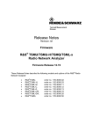
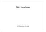
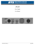
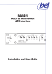
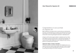
CE
Installation and Operation Manual
Model 93 Temperature limit switch
Features marked with an asterisk (*) are available only on units manufactured after January 1993 (Version 1.2).
1.89"
(48mm)
WARNING! Ensure that the
maximum voltage which is applied to the unit power supply,
between any two isolated circuits, or between any isolated
circuit and ground does not exceed 264Vac.
2.32" min.
(59mm min.)
1.77x
1.77"
+0.02
-0.00
45x +0.6
45mm -0.0
R0.020"
(R0.5mm)
max. radii
3.27" min.
(83mm min.)
Panel cutout and minimum spacing
Max. panel thickness: 0.51" (13mm)
with a screwdriver might be
necessary to secure the installation.
0.60"
(15.3mm)
1.97"
(50mm)
Dimensions
ALARM 2
Panel depth: with rear terminal cover: 4.96" (126.1mm)
with gasket fitted: less 0.060" (1.5mm)
N/O
snubber
line
2A
Com
Closed in alarm
ALARM 1
1
2
3
4
5
N/C
snubber
line
2A
Open in alarm
Alarm relay(s)
The alarm outputs are failsafe:
the relays are de-energized during the alarm condition or power
down. The attached alarm circuit
should be designed for failsafe
operation and fused appropriately. A snubber may be required;
see below.
6
7
8
9
10
12 11
Com
snubber
Power
Respect the polarity of the AC
power supply: line wire must be
connected to terminal 12, and the
neutral must be connected to terminal 11.
Reset input
Connect momentary contact, normally open pushbutton to terminals 6 and 7. Keep wiring run
shorter than 3' (1m) and well away
from noise generating circuits.
Input
WARNING! This temperature
limit switch must have its own
input sensor. Never connect the
input terminals 9 and 10 in parallel with the input of any other
instrument, e.g. recorder, controller, etc. The parallelled inputs of other instruments interfere with proper operation of
the sensor break detection circuitry and may also impair the
measurement accuracy.
NOTE: The input circuit is NOT
isolated from the reset input (terminals 6 and 7).
Use of shielded, twisted pair is
Snubbers
Connect snubbers CZ 140 398
(22nf + 100Ω) across the appropriate alarm relay contacts when
driving AC inductive loads (mechanical contactors and solenoids). Do not use snubbers
when driving high impedance
loads. The snubber passes 1mA
in 120Vac circuits, and 2mA in
240Vac circuits; this is sufficient
to hold in certain relays with high
impedance coils and should not
be used in such installations.
4.81"
(122.1mm)
Relay
Open in alarm
WARNING! When an alarm contact is to be implemented as
part of a failsafe alarm scheme,
it is the user's responsibility to
verify that the effect of the
snubber does not interfere with
the operation of the circuit. Certain high impedance circuits
are not able to detect a contact
opening when the snubber is
placed across the contact. In
these cases the snubber should
not be installed across the relay
contact.
RESET
• Prepare panel cutout.
• Install the optional front panel
gasket (part no. BO 133 297) if
required. Remove the backing
from the gasket and apply it
around the panel cutout on the
outside of the panel.
• Slide instrument sleeve into the
cutout from the front of the
panel.
• Position the mounting bracket
on the rear of the instrument
sleeve with the 2 clips facing
the rear and positioned on the
top and bottom of the sleeve.
• While holding the sleeve, slide
the mounting bracket towards
the panel until the clips engage
on the ratchets. While still pulling back on the sleeve, press
on the upper left and lower
right hand corners of the bracket to seat the mounting bracket. Another push on the clips
2. Electrical connections
I
+
V+
—
V-
INPUT
1. Mechanical installation
N/O
Relay
T/C
100-240Vac
+10/-15%
50 or 60Hz
line
neutral
1A
RTD-3
NOTE: See p. 4 for wiring of linear inputs.
recommended. The shield must
be connected to terminal 10 even
when grounded elsewhere.
• Thermocouple: Use appropriate compensation cable. Keep
loop resistance as low as possible (1kΩ maximum).
• RTD: Use 3 copper wires of
same length and diameter
3.Configuration
Procedure
1. Cycle power OFF and ON.
Touch and hold secret key
when 4-digit configuration code
appears afterself test to enter
configuration mode.
NOTE: Touching the front panel
during the start-up self test could
lead to erroneous test results.
2. See configuration code with left
digit blinking.
(20Ω/lead maximum resistance).
• Linear inputs: see page 4.
4.Operation
BASIC OPERATION
onds until Clr appears, release,
Open list procedures
then press the button again.
• Measured value is displayed
*Method 2—Use “secret key”.
when unit is unattended.
• Depress — once to view dis- Protected list procedures
play units.
• To enter protected list: use —
• Depress — again to view
until units display (°F, °C or Lin),
AL 1. Push ▲ or ▼ to view alarm then “secret key”. Continue with
1 setpoint.
— to view parameter mnemonics.
• Push ▲ or ▼ to view parame3. Enter new code (refer to Config- • Depress — again to view
AL 2. Push ▲ or ▼ to view alarm ter value. Push ▲ or ▼ again to
uration code table):
2 setpoint.
modify parameter value.
▼ = select digit position (1
• To acknowledge (or reset)
• To return to measured value
through 4)
latching alarms (flashing red AL1
display: use “secret key”.
▲ = modify digit value.
or AL2 lamp); use — until AL 1
NOTE: Parameters not pertinent
4. To exit configuration mode do
(AL 2) appears. Then do either:
to the unit configuration do not apone of these:
Secret key = accept new config- Method 1—Hold ▲ or ▼ for 5 sec- pear in the scroll list.
uration; parameter value check
follows.
display
— = abort; return to previous
secret key
configuration.
Rear terminal cover (optional)
After wiring, attach rear terminal
cover BD133125 with screw
FY133264U001.
Configuration code
1st (left) and 2nd digits
alarm 1 and alarm 2 functions
0 Disabled
1 Deviation low alarm
2 Deviation high alarm
3 Deviation band alarm
4 Full scale low alarm
5 Sensor break alarm
6 Full scale high alarm
3rd digit
input sensor type
0 RTD—100Ω Pt, DIN43760
1 B—Pt-30%Rh/Pt/6%Rh
2 C—W-5%Re/W-26%Re (Hoskins)
3 E—Chromel™/Adams constantan
4 J—Fe/SAMA constantan
5 K—Chromel™/Alumel™
6 L—Fe/Konstantan
7 N—NiCroSil/NiSil
8 Platinel II™
9 R—Pt-13%Rh/Pt
A S—Pt-10%Rh/Pt
B T—Cu/Adams constantan
C Linear a—2-point entry scaling
D Linear b—point-and-span entry
scaling
4th (right) digit
display remote ack.
0 °C
AL1 & 2
1 °C
AL1 & 2
2 °C
AL1
3 °C
AL1
4 °C
AL2
5 °C
AL2
6 °F
AL1 & 2
7 °F
AL1 & 2
8 °F
AL1
9 °F
AL1
A °F
AL2
B °F
AL2
alarm 1 active
alarm 2 active
decrease value
(DOWN button)
next parameter
increase value
(UP button)
full specified range
°F min °F max
-148
1112
1112
3308
32
3902
-436
1832
-328
2192
-418
2502
-148
1652
32
2372
-418
2543
32
3213
32
3213
-427
752
°C min
-100
600
0
-260
-200
-250
-100
0
-250
0
0
-255
°C max
600
1820
2150
1000
1200
1372
900
1300
1395
1767
1767
400
pwr fail
alarm
no
yes
no
yes
no
yes
no
yes
no
yes
no
yes
AL1
AL2
▼
▲
EUROTHERM
LIMIT SWITCH OPERATION
Temperature and process
alarms
If the measured value enters an
alarm condition (defined by the
configuration code and the parameter values), then the appropriate red lamp, AL1 or AL2, lights
and the corresponding relay deenergizes. The limit switch operation is always latching.
NOTE: Deviation alarm setpoints
(d-1 and d-2) are in reference to
the alarm setpoints (AL 1 and AL
2).
Examples: deviation low alarm
setpoint = AL 2- d-2, deviation
high alarm setpoint = AL 1 + d-1,
deviation band alarm setpoints =
AL 2 ± d-2.
Resetting (acknowledging)
alarms
Alarms are acknowledged in the
open list (see “Open list procedures”) or by a remote pushbutton.
NOTE: The remote pushbutton
can be configured to acknowledge
only AL1, only AL2 or both.
Sensor fail alarm
Sensor fail detection is always operative. The unit displays SnSr
FAIL upon detecting at least one
of these conditions:
• if the input signal is less than
-40mV or greater than +90mV,
• if the input is open circuit, or
• if the unit’s temperature is outside of the 0-55°C operating
range (thermocouple inputs only).
The behavior of the relays and the
alarm lamps AL1 and AL2 conforms to the table below.
NOTE: Selection of configuration
code “5” for digits 1 or 2 enables
the alarm relay operation only for
sensor fail alarm (and power fail
alarm if enabled) and not for any
process alarm condition.
Alarm condition
Configuration example
6646:
1st digit (6): full scale (absolute) high latching alarm (AL 1).
2nd digit (6):full scale (absolute) high latching alarm (AL 2).
3rd digit (4): type J thermocouple input.
4th digit (6): display units in °F, remote alarm acknowledgement for
both alarms, and power fail alarm disabled.
Active
Cleared
Before resetting
(unacknowledged)
lamp flashing
relay de-energized
lamp flashing
relay de-energized
After resetting
(acknowledged)
lamp steady ON
relay de-energized
lamp OFF
relay energized
Power fail alarm
• Manual reset after power restoration. If the power fail alarm is
selected (one of the “yes” selections for configuration code digit
4), the limit switch always places
both relays in the alarm state (deenergized) upon powering up. A
manual reset by the operator is
thus required to re-energize the
alarm output relays. These alarms
are acknowledged as all others in
the open list or by the remote
pushbutton.
• Automatic reset after power restoration. If the power fail alarm is
not selected (one of the “no” selections for configuration code
digit 4), the limit switch automatically re-affirms any alarm existing
before the power failure.
Alarm test
To test the operation of the output
relays and the connected circuit,
scroll to the appropriate alarm
(AL1 or AL2) in the protected list
and hold ▲ or ▼ until tESt appears. Release, then depress the
button again to change the state
of the relay: if the relay is energized, then the alarm test deenergizes the relay and vice
versa. When the button is released, the relay assumes the
previous condition determined by
the input.
Adjustable parameters
Mnemonic
Parameter
OPEN LIST
°C, °F, Lin
AL 1
Display units
Alarm 1 setpoint
Al 2
Alarm 2 setpoint
Adjustable range
PROTECTED LIST
ConF
Configuration code
Id
Instrument model ident.
dP
Decimal point position
for linear inputs a and b
AL 1
Alarm 1 setpoint
HY 1
Alarm 1 hysteresis
-d-1
Deviation alarm offset
from “AL1”
AL 2
HY 2
-d-2
OFSt
Alarm 2 setpoint
Alarm 2 hysteresis
Deviation alarm offset
from “AL 2”
Calibration offset
LinE
Line frequency
Comments
View only.
View only.
Display units selected in configuration.
To acknowledge latching alarms: Hold
UP or DOWN button until “CLr” appears,
release, then press the button again.
Value adjustable in protected list, below.
View only.
View only: “93”
0 to 2 decimal places. Formats:
XXXX, XXX.X or XX.XX
Full scale alarm setpoints and
deviation alarm reference levels:
configured input sensor range.
Can be changed upon power up only.
1°C (or 1°F) to upper range limit
Linear inputs: 1 to 9999, 0.1 to
999.9, 0.01 to 99.99
1°C (or 1°F) to upper range limit
Linear inputs: 1 to 9999, 0.1 to
999.9, 0.01 to 99.99
Same as alarm 1.
-50.0 to 50.0°C
-90.0 to 90.0°F
50 Hertz: “50”; 60 Hertz: “60”
Appears for linear inputs only. Affects all
parameters displayed in process units.
Alarm function selected in configuration.
“AL 1” setting irrelevant for sensor break
alarms: configuration code “5”.
To test alarm operation: Hold UP or
DOWN button until “tESt” appears,
release, then press the button again.
Alarm state should toggle.
Appears for deviation configurations only.
For deviation band alarms, “HY1”
must be less than “-d-1”.
Same as alarm 1.
Appears for temperature inputs only.
Set to line frequency upon installation.
Display messages
Message
Display condition
INPUT STATUS MESSAGES
SnSr
Sensor fail. Input open or reversed; measured
FAIL
value outside of configured range.
flashing
Display overrange or out of specified accuracy
value
range.
SELF DIAGNOSTIC MESSAGES
tESt
Internal self test upon power up.
1111
8888
EE
FAIL
Id
FAIL
Display test after above self test. Lasts for
approximately 3 seconds.
Memory corruption.
Unit failure.
User action/comments
Verify input sensor and connections. Message
disappears when input signal is reinstated.
Unit should not be used in this range.
Replace unit if all four 1's do not light up or
fails to go on to “8888” display.
Do not touch front panel during self test.
User should verify that all digits and lamps light
up to prevent erroneous readings.
Cycle power. Verify and correct all parameter
and configuration values. If display persists,
replace unit.
Replace unit.
Please note the following:
• Conductive pollution, such as carbon dust, must be excluded from the cabinet in which the instrument is mounted.
• Any voltage transients that occur on power supply lines, isolated inputs or outputs must not exceed 2.5V (in series or common mode). If occational voltage transients of 2.5kV or higher are expected or measured, transient limiting devices should be
part of installation.
0-20mA and 4-20mA input
LINEAR INPUT SCALING
In.Lo
Input for low setup point
9
3.01Ω
10
9
R
1.0kΩ
V
dSLo
10
In.Hi
Display value for low
setup point
Input for high setup point
Voltage inputs
Nominal range
-20 to 200mV
-0.1 to 1 V
-0.5 to 5V
-1 to 10V
-2.5 to 25V
R
2.2kΩ
15.0kΩ
75.0kΩ
150kΩ
392kΩ
CAUTION!
Before installing, operating or servicing this unit supplied by
Eurotherm, please read the following:
INSTRUCTIONS FOR SAFE
USE OF EUROTHERM
EQUIPMENT
(Note: These instructions represent good engineering principles
and are applicable to all control
equipment of the same type,
whether from Eurotherm or any
other supplier.)
ENCLOSURE OF LIVE PARTS
This unit should be installed inside a suitable grounded metal
enclosure to prevent live parts
being accessible to human hands
and metal tools. It is recommended that rear terminal covers (available as an option) be fitted.
WIRING
It is important to connect the unit
correctly in accordance with the
installation data on this sheet.
Wiring should conform to appropriate standards of good practice
and local codes and regulations.
Conductors should be commensurate with voltage and current
ratings of the units.
OUT-OF-LIMITS ALARMS
In applications where excessive
dSHi
In.Sn
dSSn
Display value for high
setup point
Input signal span
Display span
deviation of a controlled parameter due to equipment failure could
cause damage to machinery or
materials, or injury to personnel, it
is strongly recommended that an
additional separate unit with its
own input sensor be used to give
alarm indication or to shut down
the process or both, as may be
appropriate. (Note: The alarm
function built into controllers may
not give sufficient protection in
these circumstances). When the
controller alarm function or separate alarm units are used they
should be checked for correct operation at regular intervals.
CONFIGURATION
Many instrument functions are
user selectable from the front
panel. It is the user's responsibility
to verify that the instrument configuration is correct. Personal injury, property loss and equipment
damage could result from an improperly configured instrument.
GROUNDING
This instrument has internal circuits which are isolated or “floating.” This is necessary to prevent
the occurrence of a “ground loop”
in signal circuits. To avoid possible shock hazards in the event of
an internal fault causing break-
4. Scroll to dSLo. Then set in
the corresponding display value
with ▲ or ▼.
Linear a only
5. Again, if reading the input signal directly from the source, apply
a signal equal to a known high
value for the second setup point.
6. Scroll through the protects list
until In.Hi. Press on ▲ or ▼ until
rEAd appears, release, then push
the button again. [Alternatively, if
dSHi
display units
I
Scaling procedure
There are 2 methods for entering
and scaling linear inputs:
• Linear a: 2-point scaling (configuration code “C”).,
• Linear b: point and span scaling (configuration code “D”).
Linear a and Linear b
1. Set display decimal point position parameter, dP, to desired
value.
2. If reading the input signal directly from the source, connect
source (from signal generator or
sensor) to input terminals. Apply a
signal equal to a known low value
for the first setup point.
3. Scroll through the protected
list until In.Lo. Press and hold on
▲ or ▼ until rEAd appears, release, then push the button again.
[Alternatively, if no input signal is
required or the exact value is
known, the input value in millivolts
can be set in with ▲ or ▼.]
display units
LINEAR INPUT SETUP
Electrical connections
For all inputs use a shielded twisted pair.
• Millivolt inputs (-10 to 70mV).
Connect signal leads directly to
input terminals 9 (+) and 10 (-).
• 0-20mA and 4-20mA inputs.
Connect 3.01Ω shunt (part no. CA
9G3 R01) across input terminals
9 (+) and 10 (-).
• Higher voltage inputs. Voltage
divider network is required (resistors supplied by user). Refer to
table for suggested values. Resistor specifications: 1%, 0.125W
minimum, ±100ppm metal or
metal oxide film.
CAUTION: Use of the shunt or
voltage divider inhibits operation of the sensor break detection feature.
dSLo
no input signal is required or the
exact value is known, the input
value in millivolts can be set in
with ▲ or ▼.]
7. Access dSHi. Then set in the
corresponding display value with
▲ or ▼.
Linear b only
8. Access In.Sn. With ▲ or ▼
set in the input signal span in millivolts.
9. Access dSSn. With ▲ or ▼
se
t
in
th
e
dSSn
dSLo
In.Lo
In.Hi
input (mV)
Linear a: 2-point scaling
In.Sn
In.Lo
input (mV)
Linear b: point & span scaling
(Replaces “OFSt” parameter in protected list)
-9.99 to 70.00mV input signal
Both linear a and b inputs. To read input
range
signal value from rear terminals: Hold UP
or DOWN until “rEAd” appears, release,
then press the button again.
-999 to 9999, -99.9 to 999.9, or
Both linear a and b inputs.
-9.99 to 99.99 process units
-9.99 to 70.00mV input signal
Linear a inputs only. To read input signal
range
value from rear terminals: See procedure
for “In.Lo”, above.
-999 to 9999, -99.9 to 999.9, or
Linear a inputs only.
-9.99 to 99.99 process units
0.00 to 70.00mv
Linear b inputs only.
-999 to 9999, -99.9 to 999.9, or
Linear b inputs only.
-9.99 to 99.99 process units
down of insulation, it is recommended that all equipment connected to this unit be enclosed in
a grounded metal enclosure.
Sheaths of thermocouples (or
other sensors) should be properly
grounded by a separate conductor (instead of being dependent
on grounding via the machine
framework).
ESD PRECAUTIONS
This instrument contains static
sensitive components. Care
should be taken to avoid electrostatic discharge (ESD) and thus
reduce incidents of damage to the
instrument when removed from its
sleeve. Any manipulation of an
unsleeved instrument should be
performed on a conductive surface with the personnel in contact
with the surface by means of a
grounded, metal or conductive
plastic wrist strap with a 1MΩ series resistor.
SUPPLY ISOLATORS
Every electrical system should be
provided with means for isolating
the system from the AC supply to
allow safe working during repair
and maintenance. SCRs and
triacs are not adequate means of
isolating the supply, and should
always be backed by a suitable
mechanical disconnect switch.
HAZARDOUS ATMOSPHERES
This unit is not suitable for use in
areas subject to hazardous atmospheres. No Eurotherm product
should be connected to a circuit
which passes into or through a
hazardous area unless appropriate precautions are taken (even
though the instrument itself may
be located in a safe area). Such
an installation should conform to
the requirements of the relevant
Authority. (In the USA: Factory
Mutual Research Corporation and
Underwriters' Laboratories, Inc.).
PROCEDURE IN THE EVENT OF
TROUBLE
Before beginning any investigation
of a fault, the electrical supplies to
all equipment concerned should
be switched off and isolated. Units
suspected of being faulty should
be disconnected and removed to a
properly equipped workshop for
testing. There are no userservicable parts inside this unit.
© 1990, 93, 96
Eurotherm Controls Inc
All rights reserved.
Doc. HA133642 Issue 3 9608