1
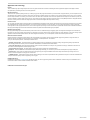
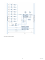
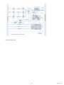
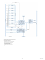
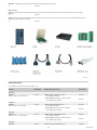
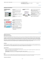
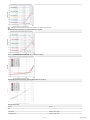
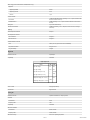
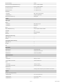
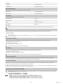
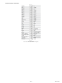
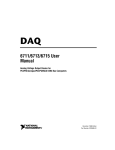
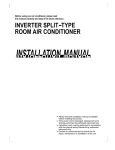
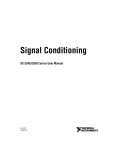
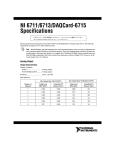
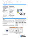
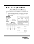
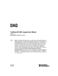
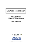
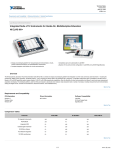
Technical Sales
(866) 531-6285
[email protected]
Requirements and Compatibility | Ordering Information | Detailed Specifications | Pinouts/Front Panel Connections
For user manuals and dimensional drawings, visit the product page resources tab on ni.com.
Last Revised: 2014-11-06 07:14:22.0
High-Speed Voltage Output – Up to 1 MS/s/Channel, up to 16 Bits, up to 32 Channels
Low-cost arbitrary waveform generation and high-channel density
8 digital I/O lines (TTL/CMOS)
Integrated multidevice synchronization bus
Two 24-bit counter/timers
Digital triggering and external clocking
Measurement services that simplify configuration and measurements
Simultaneous updates
Overview
NI 671x high-speed voltage output devices combine the latest in PC technologies to deliver simultaneous, multichannel updates for control and waveform output applications. Use
these modules in a variety of applications, including stimulus-response, power supply control, high-speed, deterministic control, sensor/signal simulation.
Back to Top
Requirements and Compatibility
OS Information
Driver Information
Linux®
Software Compatibility
NI-DAQmx
Visual Basic
Mac OS X
Visual C#
Windows 2000/XP
Visual C++
Windows NT
Visual Studio .NET
Windows Vista x64/x86
Back to Top
Comparison Tables
Family
Analog
Output
Bus
Update Rate per
Channel (S/s)
Output
Resolution
Output
Range (V)
External Voltage
Reference
Digital
Counter/Timers Triggering
I/O
NI 6711 PCI, PXI 4
1M
12
±10
yes
8
2, 24-bit
Digital
NI 6713 PCI, PXI 8
740 k to 1M
12
±10
yes
8
2, 24-bit
Digital
NI 6715 PCMCIA 8
100 k to 1M
12
±10
yes
8
2, 24-bit
Digital
NI 6722 PCI, PXI 8
182 to 800 k
13
±10
no
8
2, 24-bit
Digital
NI 6723 PCI, PXI 32
45 to 800 k
13
±10
no
8
2, 24-bit
Digital
NI 6731 PCI
1M
16
±10
yes
8
2, 24-bit
Digital
740 k to 1M
13
±10
yes
8
2, 24-bit
Digital
4
NI 6733 PCI, PXI 8
Back to Top
1/17
www.ni.com
Application and Technology
Features
These versatile NI high-speed voltage output devices commonly replace several kinds of instruments including stand-alone proportional integral derivative (PID) controllers,
low-speed arbitrary waveform generators, and function generators.
Waveform Generation
These devices are capable of updating at rates up to 1 MS/s, giving you the ability to generate waveforms up to 500 kHz. When using these devices, you have complete control of
each data point that is updated on the output for each channel. This feature is significant because you can define not only common waveforms such as square, sine, or sawtooth
but also complex waveforms. For instance, you are able to create a sine wave that is overlaid with noise in which the amplitude and noise shape are user-defined. In practice, the
waveform is defined in a software buffer, within PC memory, and is streamed to the voltage output device using direct memory access (DMA) data transfers. Using DMA transfers,
the amount of memory located on board the voltage output device is minimized and swapped with inexpensive PC memory.
Real-Time Control
You can use NI high-speed voltage output devices with the NI LabVIEW Real-Time Module to deliver real-time, deterministic control loop execution. Because they are compatible
with LabVIEW Real-Time, common control algorithms, such as PID, are simple to implement but, more importantly, you may prototype and implement complex, cutting-edge
control algorithms as well. High-performance control, on the order of eight PID loops running in excess of 20 kHz each, is possible with this combination of hardware and software.
Each high-speed voltage output device offers multichannel simultaneous updates and hardware-timed single-point updates.
Multidevice Synchronization
Each high-speed voltage output device offers the ability to be master or slave of a multidevice timing and triggering system. Use integration technologies such as the RTSI bus,
PXI trigger bus, and PFI pins to trigger and synchronize to a wide variety of I/O types. These I/O types range from analog input, image acquisition, motion control, and high-speed
digitizers to multifunction data acquisition devices. With these integration infrastructures, you can create powerful, custom test and control systems with ease.
Measurement Services Software
National Instruments measurement services software, built around NI-DAQmx driver software, features intuitive application programming interfaces, configuration tools, I/O
assistants, and other tools designed to reduce system setup, configuration, and development time. This software,
part of your data acquisition purchase, includes helpful features such as:
Automatic code generation – The DAQ Assistant is an interactive guide that helps you navigate through configuring, testing, and programming analog output tasks and
automatically generates the necessary code for NI LabVIEW, LabWindows/CVI, and Measurement Studio software.
Cleaner code development – Basic and advanced software functions have been combined into one easy-to-use yet powerful set to help you build cleaner code and move
from basic to advanced applications without replacing functions.
High-performance driver engine – NI-DAQmx delivers maximum I/O system throughput with a multithreaded driver.
Test panels – With the NI Measurement & Automation Explorer (MAX) configuration utility, you can test all of your module functionality before you begin development.
Scaled channels – Easily scale your voltage data into the proper engineering units using the NI-DAQmx measurement-ready virtual channels by choosing from a list of
common sensors and signals or creating your own custom scale.
LabVIEW integration – All NI-DAQmx functions create the waveform data type, which carries acquired data and timing information directly into more than 400 LabVIEW built-in
analysis routines for display of results in engineering units on a graph.
NI-DAQmx Base Driver
NI-DAQmx Base (available at ni.com/downloads) offers Mac OS X and Linux users a programming interface similar to NI-DAQmx. It features ready-to-use LabVIEW VIs and C
function features similar to those included in NI-DAQmx driver software.
NI DAQCard-6715 Hardware Block Diagram
2/17
www.ni.com
NI 671x and NI 673x Hardware Block Diagram
3/17
www.ni.com
NI 672x Hardware Block Diagram
4/17
www.ni.com
High-Speed Voltage Output Cables and Accessories
Recommended Configurations
Shielded options for minimal noise interference
Direct connectivity options such as BNC
Low-cost options for OEM
Front-mount terminal block for PXI
Custom connectivity with the CA-1000
5/17
www.ni.com
I/O Connector Blocks
BNC-2110 – Shielded I/O connector block with signal-labeled BNC connectors for easy connectivity of your analog output (AO), digital I/O (DIO), and counter/timer signals.
Dimensions – 20.3 by 11.2 by 5.5 cm (8.0 by 4.4 by 2.2 in.)
BNC-2110..............................................................................777643-01
BNC-2115 – Shielded I/O connector block with signal-labeled BNC connectors for easy connectivity of your extended analog output on NI 6723 devices. Dimensions – 20.3 by
11.2 by 5.5 cm (8.0 by 4.4 by 2.2 in.)
BNC-2115..............................................................................777807-01
SCB-68 – Shielded I/O connector block that gives you rugged, very low-noise signal termination. The SCB-68 also houses silk-screened component locations for easy addition of
simple signal conditioning circuitry for your AO channels. Dimensions – 19.5 by 15.2 by 4.5 cm (7.7 by 6.0 by 1.8 in.)
SCB-68 ..................................................................................776844-01
CA-1000 – Configurable enclosure that gives you user-defined connectivity and flexibility through customized panelettes. Dimensions – 30.7 by 25.4 by 4.3 cm (12.1 by 10 by 1.7
in.)
CA-1000 ..............................................................................777664-01
TBX-68 – 68 screw terminals for easy connection of field signals to 68-pin DAQ devices. It includes one 68-pin male connector for direct connection to 68-pin cables. The TBX-68
is mounted in a protective plastic base with hardware for mounting on a standard DIN rail. Dimensions – 12.50 by 10.74 cm (4.92 by 4.23 in.)
TBX-68 ..................................................................................777141-01
CB-68LP, CB-68LPR – 68 screw terminals for easy connection of field signals to AO devices. They include one 68-pin male connector for direct connection to 68-pin cables. The
connector blocks include standoffs for use on a desktop or for mounting in a custom panel. The CB-68LP has a vertical mounted 68-pin connector. The CB-68LPR has a
right-angle mounted connector and can also be used with the CA-1000. Dimensions – 14.35 by 10.74 cm (5.65 by 4.23 in.);7.62 by 16.19 cm (3.00 by 6.36 in.)
CB-68LP ................................................................................777145-01
CB-68LPR..............................................................................777145-02
TB-2705 – 68-pin screw-terminal block for NI PXI-671x and PXI-673x modules. Latches to the front of your PXI module with locking screws and provides strain relief as well as
easy access to your analog, digital, trigger, and counter/timer signals through screw terminals. Does not work with NI 6703 or NI 6704 devices. Dimensions – 8.43 by 10.41 by
2.03 cm (3.32 by 4.1 by 0.8 in.)
TB-2705 ................................................................................778241-01
Synchronization Cables
RTSI Bus Cables – Used to connect timing and synchronization signals among measurement, vision, motion, and CAN boards for PCI. For systems with long and short boards,
use the extended RTSI cable.
2 boards . . . . . . . . . . . . . . . . . . . . . . . . . . . . . . . . . . . . . . .776249-02
3 boards . . . . . . . . . . . . . . . . . . . . . . . . . . . . . . . . . . . . . . .776249-03
4 boards . . . . . . . . . . . . . . . . . . . . . . . . . . . . . . . . . . . . . . .776249-04
5 boards . . . . . . . . . . . . . . . . . . . . . . . . . . . . . . . . . . . . . . .776249-05
Extended, 5 boards . . . . . . . . . . . . . . . . . . . . . . . . . . . . . . .777562-05
Shielded I/O Cables
SH68-68-EP – Shielded 68-conductor cable terminated with two 68-pin female 0.050 series D type connectors, featuring individually shielded analog twisted pairs for reduced
crosstalk with high-speed devices. This cable works with all NI 671x and NI 673x devices.
1 m . . . . . . . . . . . . . . . . . . . . . . . . . . . . . . . . . . . . . . . . . . . .184749-01
SHC68-68-EP – Shielded cable for connecting and latching the NI DAQCard-6715, NI 6722, and NI 6723 devices to standard 68-pin accessories. Latching screws secure the
shielded connector to the device itself for stability. Use this cable for a DAQCard located in the bottom PCMCIA slot of a laptop.
0.5 m . . . . . . . . . . . . . . . . . . . . . . . . . . . . . . . . . . . . . . . . .186838-0R5
1 m . . . . . . . . . . . . . . . . . . . . . . . . . . . . . . . . . . . . . . . . . .186838-01
SHC68U-68-EP – Identical to the SHC68-68-EP except the DAQCard connector is inverted so you can use two latching DAQCard devices in adjacent slots. Use this cable with a
DAQCard inserted in the upper PCMCIA slot of a laptop.
0.5 m . . . . . . . . . . . . . . . . . . . . . . . . . . . . . . . . . . . . . . . . .187406-0R5
1 m . . . . . . . . . . . . . . . . . . . . . . . . . . . . . . . . . . . . . . . . . . 187406-01
6/17
www.ni.com
SH68-C68-S – Shielded cable for connecting and latching NI 672x devices to standard 68-pin accessories.
2 m . . . . . . . . . . . . . . . . . . . . . . . . . . . . . . . . . . . . . . . . . . . .186381-02
Ribbon I/O Cables
R6868 – 68-conductor flat ribbon cable terminated with two 68-pin connectors. Use this cable to connect the NI 670x, NI 671x, and NI 673x devices to low-cost 68-pin
accessories.
1 m . . . . . . . . . . . . . . . . . . . . . . . . . . . . . . . . . . . . . . . . . . . .182482-01
RC68-68 – 68-conductor flat ribbon cable terminated with one VHDCI 68-pin connector and one 68-pin SCSI II connector. Use this cable to connect NI 6722 devices and the
DAQCard-6715 with standard 68-pin accessories.
1 m . . . . . . . . . . . . . . . . . . . . . . . . . . . . . . . . . . . . . . . . . . . .187252-01
Back to Top
Ordering Information
For a complete list of accessories, visit the product page on ni.com.
Products
Part Number
Recommended Accessories
Part Number
NI PCI-6711
NI PCI-6711
Requires: 1 Cables , 1 Connector Blocks ;
777740-01
Cables: Shielded - SH68-68-EP Cable (2m)
**Also Available: [Unshielded]
Connector Blocks: Spring-Screw_Terminals - SCB-68A
**Also Available: [BNC_Terminals]
184749-02
782536-01
NI PXI-6711
NI PXI-6711
Requires: 1 Cable , 1 Connector Block ;
777794-01
Cable: Shielded - SH68-68-EP Cable (2m)
**Also Available: [Unshielded]
Connector Block: Spring-Screw_Terminals - SCB-68A
**Also Available: [BNC_Terminals]
184749-02
782536-01
NI PCI-6713
NI PCI-6713
Requires: 1 Cables , 1 Connector Blocks ;
777741-01
Cables: Shielded - SH68-68-EPM Cable (2m)
**Also Available: [Unshielded]
199006-02
Connector Blocks: Spring-Screw_Terminals - SCB-68A
**Also Available: [BNC_Terminals]
782536-01
Cable: Shielded - SH68-68-EPM Cable (2m)
199006-02
NI PXI-6713
NI PXI-6713
777795-01
7/17
www.ni.com
Requires: 1 Cable , 1 Connector Block ;
**Also Available: [Unshielded]
Connector Block: Spring-Screw_Terminals - SCB-68A
**Also Available: [BNC_Terminals]
782536-01
Back to Top
Software Recommendations
LabVIEW Professional
Development System for
Windows
NI LabWindows™/CVI for
Windows
Advanced software tools for large project
development
Automatic code generation using DAQ
Assistant and Instrument I/O Assistant
Complete hardware compatibility with IVI,
VISA, DAQ, GPIB, and serial
Analysis tools for array manipulation, signal
processing statistics, and curve fitting
Tight integration with a wide range of
hardware
Advanced measurement analysis and digital
signal processing
Open connectivity with DLLs, ActiveX, and
.NET objects
Simplified cross-platform communication with
network variables
Measurement Studio .NET tools (included in
LabWindows/CVI Full only)
The mark LabWindows is used under a
license from Microsoft Corporation.
Capability to build DLLs, executables, and
MSI installers
NI Measurement Studio
Professional Edition
Real-time advanced 2D graphs and charts
Customizable graphs and charts for WPF,
Windows Forms, and ASP.NET Web Forms
UI design
Analysis libraries for array operations, signal
generation, windowing, filters, signal
processing
Hardware integration support with native
.NET data acquisition and instrument control
libraries
Automatic code generation for all NI-DAQmx
data acquisition hardware
Intelligent and efficient data-logging libraries
for streaming measurement data to disk
Support for Microsoft Visual Studio .NET
2012/2010/2008
Back to Top
Support and Services
System Assurance Programs
NI system assurance programs are designed to make it even easier for you to own an NI system. These programs include configuration and deployment services for your NI PXI,
CompactRIO, or Compact FieldPoint system. The NI Basic System Assurance Program provides a simple integration test and ensures that your system is delivered completely
assembled in one box. When you configure your system with the NI Standard System Assurance Program, you can select from available NI system driver sets and application
development environments to create customized, reorderable software configurations. Your system arrives fully assembled and tested in one box with your software preinstalled.
When you order your system with the standard program, you also receive system-specific documentation including a bill of materials, an integration test report, a recommended
maintenance plan, and frequently asked question documents. Finally, the standard program reduces the total cost of owning an NI system by providing three years of warranty
coverage and calibration service. Use the online product advisors at ni.com/advisor to find a system assurance program to meet your needs.
Calibration
NI measurement hardware is calibrated to ensure measurement accuracy and verify that the device meets its published specifications. To ensure the ongoing accuracy of your
measurement hardware, NI offers basic or detailed recalibration service that provides ongoing ISO 9001 audit compliance and confidence in your measurements. To learn more
about NI calibration services or to locate a qualified service center near you, contact your local sales office or visit ni.com/calibration.
Technical Support
Get answers to your technical questions using the following National Instruments resources.
Support - Visit ni.com/support to access the NI KnowledgeBase, example programs, and tutorials or to contact our applications engineers who are located in NI sales
offices around the world and speak the local language.
Discussion Forums - Visit forums.ni.com for a diverse set of discussion boards on topics you care about.
Online Community - Visit community.ni.com to find, contribute, or collaborate on customer-contributed technical content with users like you.
Repair
While you may never need your hardware repaired, NI understands that unexpected events may lead to necessary repairs. NI offers repair services performed by highly trained
technicians who quickly return your device with the guarantee that it will perform to factory specifications. For more information, visit ni.com/repair.
Training and Certifications
8/17
www.ni.com
The NI training and certification program delivers the fastest, most certain route to increased proficiency and productivity using NI software and hardware. Training builds the skills
to more efficiently develop robust, maintainable applications, while certification validates your knowledge and ability.
Classroom training in cities worldwide - the most comprehensive hands-on training taught by engineers.
On-site training at your facility - an excellent option to train multiple employees at the same time.
Online instructor-led training - lower-cost, remote training if classroom or on-site courses are not possible.
Course kits - lowest-cost, self-paced training that you can use as reference guides.
Training memberships and training credits - to buy now and schedule training later.
Visit ni.com/training for more information.
Extended Warranty
NI offers options for extending the standard product warranty to meet the life-cycle requirements of your project. In addition, because NI understands that your requirements may
change, the extended warranty is flexible in length and easily renewed. For more information, visit ni.com/warranty.
OEM
NI offers design-in consulting and product integration assistance if you need NI products for OEM applications. For information about special pricing and services for OEM
customers, visit ni.com/oem.
Alliance
Our Professional Services Team is comprised of NI applications engineers, NI Consulting Services, and a worldwide National Instruments Alliance Partner program of more than
700 independent consultants and integrators. Services range from start-up assistance to turnkey system integration. Visit ni.com/alliance.
Back to Top
Detailed Specifications
This document lists the specifications for the NI 6711/6713 and NI DAQCard-6715 analog output devices. The following specifications are typical at 25 °C unless otherwise noted.
Note With NI-DAQmx, National Instruments has revised its terminal names so they are easier to understand and more consistent among NI hardware and software
products. The revised terminal names used in this document are usually similar to the names they replace. For a complete list of Traditional NI-DAQ (Legacy) terminal
names and their NI-DAQmx equivalents, refer to the Terminal Name Equivalents section of Chapter 2, I/O Connector, of the Analog Output Series User Manual .
Analog Output
Output Characteristics
Number of channels
NI 6711
4 voltage outputs
NI 6713/DAQCard-6715
8 voltage outputs
Resolution
12 bits, 1 in 4,096
Max update rate
Number of Channels
Max Update Rate (NI 6711/6713)
Using Local FIFO (kS/s)
1
Using Host PC Memory (kS/s)
Max Update Rate (NI DAQCard-6715)
2
Using Local FIFO (kS/s) Using Host PC Memory (kS/s) 3
1
1,000
1,000
1,000
833
2
1,000
1,000
850
417
3
1,000
1,000
750
282
4
1,000
1,000
650
211
5
1,000
1,000
600
169
6
952
1,000
550
141
7
833
869
510
121
8
740
769
480
105
Type of DAC
NI 6711/6713
Double-buffered, multiplying
NI DAQCard-6715
Serial, multiplying
FIFO buffer size
NI 6711/DAQCard-6715
8,192 samples
NI 6713
16,384 samples
9/17
www.ni.com
DMA channels (NI 6711/6713 only)
3
Data transfers
NI 6711/6713
DMA, interrupts, programmed I/O
NI DAQCard-6715
Interrupts, programmed I/O
DMA modes (NI 6711/6713 only)
Scatter-gather
Accuracy Information
Nominal Range at Full Scale (V)
Absolute Accuracy
% of Reading
24 Hours 90 Days
±10
0.0177%
Offset (mV) Temp Drift (%/°C)
1 Year
0.0197% 0.0219% ±5.933
0.0005%
Absolute accuracy = (% of Reading × Voltage) + Offset + (Temp Drift × Voltage)
Note Temp drift applies only if ambient is greater than ±10 °C of previous external calibration.
Transfer Characteristics
Relative accuracy (INL)
After calibration
±0.3 LSB typ, ±0.5 LSB max
Before calibration
±4.0 LSB max
DNL
After calibration
±0.3 LSB typ, ±1.0 LSB max
Before calibration
±3.0 LSB max
Monotonicity
12 bits guaranteed after calibration
Offset error
After calibration
±1.0 mV typ, ±5.9 mV max
Before calibration
±200 mV max
Gain error (relative to internal reference)
After calibration
±0.01% of output max
Before calibration
±0.5% of output max
Gain error (relative to external reference)
+0.0 to +0.67% of output max, not adjustable at > 4 V
Voltage Output
Ranges
±10 V, ±EXT REF
Output coupling
DC
Output impedance
0.1 Ω max
Current drive
±5 mA max
Output stability
Any passive load, up to 1,500 pF
Protection
Short-circuit to ground
Power-on state
0 V (±200 mV)
External Reference Input
Range
±11 V
Overvoltage protection
±25 V powered on, ±15 V powered off
Input impedance
10 kΩ
NI 6711/6713 Scaling Attenuation versus External Reference Frequency
10/17
www.ni.com
Note (NI 6711/6713 Only) External reference input is always a 1.414 V peak-to-peak sine wave.
NI DAQCard-6715 Scaling Attenuation versus External Reference Frequency
NI 6711/6713 AO External Reference THD versus External Reference Frequency
NI DAQCard-6715 AO External Reference THD versus External Reference Frequency
Dynamic Characteristics
Slew rate
20 V/μs
Noise
NI 6711/6713
200 μVrms, DC to 1 MHz
NI DAQCard-6715
400 μVrms, DC to 1 MHz
11/17
www.ni.com
Glitch energy (at mid-scale transition, NI DAQCard-6715 only)
Magnitude
Reglitching disabled
±20 mV
Reglitching enabled
±4 mV
Duration
1.5 μs
Channel crosstalk
–70 dB with SH68-68-EP cable (generating a 10 V, 10 point sinusoidal at 100
kHz on the reference channel)
–60 dB (generating a 10 V, 10 point sinusoidal at 100 kHz on the reference
channel)
NI 6711/6713
NI DAQCard-6715
Settling time
3.0 μs to ±0.5 LSB accuracy
Total harmonic distortion
–80 dB typ (generating a 10 V, 1,000 point, 750 Hz sine wave, summing 9
harmonics)
Stability
Offset temperature coefficient
±50 μV/°C
Gain temperature coefficient
Internal reference
±25 ppm/°C
External reference
±25 ppm/°C
Onboard calibration reference
Level
5.000 V (±2.5 mV) (actual value stored in EEPROM)
Temperature coefficient
±5.0 ppm/°C max
Long-term stability
±15 ppm/
Digital I/O
Number of channels
8 input/output
Compatibility
TTL/CMOS
Digital logic levels
Level
Min
Max
Input low voltage
0V
0.8 V
Input high voltage
2.0 V
5.0 V
Input low current (Vin = 0 V)
—
–320 μA
Input high current (Vin = 5 V)
—
10 μA
Output low voltage (IOL = 24 mA)
—
0.4 V
Output high voltage (IOH = –13 mA) 4.35 V —
Power-on state
Input (high-impedance)
Data transfers
Programmed I/O
Timing I/O
Number of channels
2 up/down counter/timers, 1 frequency scaler
Resolution
Counter/timers
24 bits
Frequency scaler
4 bits
Compatibility
TTL/CMOS
Base clocks available
Counter/timers
20 MHz, 100 kHz
Frequency scaler
10 MHz, 100 kHz
Base clock accuracy
±0.01% over operating temperature
12/17
www.ni.com
Max source frequency
20 MHz
External source selections (NI DAQCard-6715 only)
PFI <0..9>, software-selectable
External gate selections (NI DAQCard-6715 only)
PFI <0..9>, software-selectable
Min source pulse duration
10 ns, edge-detect mode
Min gate pulse duration
10 ns, edge-detect mode
Data transfers
NI 6711/6713
DMA, interrupts, programmed I/O
NI DAQCard-6715
Interrupts, programmed I/O
DMA modes (NI 6711/6713 only)
Scatter-gather
Triggers
Digital Trigger
Purpose
Analog output
Start trigger, gate, clock
Counter/timers
Source, gate
Source
PFI <0..9>
Slope (NI DAQCard-6715 only)
Positive or negative; software-selectable
Compatibility
TTL
Response
Rising or falling edge
Pulse width
10 ns min
RTSI Bus (PCI-6711/6713 Only)
Trigger lines <0..6>
7
RTSI clock
1
PXI Trigger Bus (PXI-6711/6713 Only)
Trigger lines <0..5>
6
Star trigger
1
Clock
1
Bus Interface
NI PCI-6711/6713
5 V PCI master, slave
NI PXI-6711/6713
PXI/CompactPCI master, slave
NI DAQCard-6715
16-bit PC Card (PCMCIA)
Power Requirement
NI 6711
+5 VDC (±5%)
0.80 A typ, 1.0 A max
Power available at I/O connector
+4.65 to +5.25 VDC at 1 A
NI 6713
+5 VDC (±5%)
1.25 A typ, 1.5 A max
Power available at I/O connector
+4.65 to +5.25 VDC at 1 A
NI DAQCard-6715
+5 VDC (±5%)
160 mA typ, 250 mA max plus any current used from the I/O connector
Physical
Dimensions (not including connectors)
NI PCI-6711/6713
17.5 × 10.7 cm (6.87 × 4.2 in.)
NI PXI-6711/6713
16 × 10 cm (6.3 × 3.9 in.)
NI DAQCard-6715
Type II PC Card
13/17
www.ni.com
I/O connector
NI 6711/6713
68-pin male SCSI-II type
NI DAQCard-6715
68-pin female Honda connector
Maximum Working Voltage
Maximum working voltage refers to the signal voltage plus the common-mode voltage.
Channel-to-earth
±11 V, Installation Category I
Channel-to-channel
±22 V, Installation Category I
Environmental
The NI 6711/6713/DAQCard-6715 is intended for indoor use only.
Operating temperature
0 to 50 °C
Storage temperature
–20 to 70 °C
Humidity
5 to 90% RH, noncondensing
Maximum altitude
2,000 meters
Pollution Degree
2
Note Clean the device with a soft, non-metallic brush. Make sure that the device is completely dry and free from contaminants before returning it to service.
Safety
This product is designed to meet the requirements of the following standards of safety for electrical equipment for measurement, control, and laboratory use:
IEC 61010-1, EN 61010-1
UL 61010-1, CSA 61010-1
Note For UL and other safety certifications, refer to the product label, or visit ni.com/ certification, search by model number or product line, and click the appropriate link
in the Certification column.
Electromagnetic Compatibility
This product is designed to meet the requirements of the following standards of EMC for electrical equipment for measurement, control, and laboratory use:
EN 61326 EMC requirements; Minimum Immunity
EN 55011 Emissions; Group 1, Class A
CE, C-Tick, ICES, and FCC Part 15 Emissions; Class A
Note For EMC compliance, operate this device with shielded cabling.
CE Compliance
This product meets the essential requirements of applicable European Directives, as amended for CE marking, as follows:
2006/95/EC; Low-Voltage Directive (safety)
2004/108/EC; Electromagnetic Compatibility Directive (EMC)
Note For the standards applied to assess the EMC of this product, refer to the Online Product Certification section.
Online Product Certification
Refer to the product Declaration of Conformity (DoC) for additional regulatory compliance information. To obtain product certifications and the DoC for this product, visit
ni.com/certification, search by module number or product line, and click the appropriate link in the Certification column.
Environmental Management
National Instruments is committed to designing and manufacturing products in an environmentally responsible manner. NI recognizes that eliminating certain hazardous
substances from our products is beneficial not only to the environment but also to NI customers.
For additional environmental information, refer to the NI and the Environment Web page at ni.com/environment. This page contains the environmental regulations and directives
with which NI complies, as well as other environmental information not included in this document.
Waste Electrical and Electronic Equipment (WEEE)
EU Customers At the end of their life cycle, all products must be sent to a WEEE recycling center. For more information about WEEE recycling centers and National
Instruments WEEE initiatives, visit ni.com/environment/weee.htm.
14/17
www.ni.com
1
These numbers apply to continuous waveform generation, which allows for the time it takes to reset the FIFO to the beginning when cycling through it. This additional time,
about 200 ns, is not incurred when using host PC memory for waveform generation. Max update rate in FIFO mode does not change regardless of the number of devices in the
system.
2
These results were measured using a PCI-6711/6713 device with a 90 MHz Pentium machine. These numbers may change when using more devices or when other CPU or bus
activity occurs.
3
These results were measured using a DAQCard-6715 with a 266 MHz Pentium II machine. These numbers may change when using more devices or when other CPU or bus
activity occurs.
Back to Top
15/17
www.ni.com
Pinouts/Front Panel Connections
NI 6711 68-Pin AO I/O Connector Pin Assignments
16/17
www.ni.com
NI 6713/DAQCard-6715 68-Pin AO I/O Connector Pin Assignments
Back to Top
©2009 National Instruments. All rights reserved. CompactRIO, CVI, DAQCard, FieldPoint, LabVIEW, Measurement Studio, MITE, National Instruments, National Instruments Alliance Partner, NI, ni.com, and RTSI
are trademarks of National Instruments. The mark LabWindows is used under a license from Microsoft Corporation. Windows is a registered trademark of Microsoft Corporation in the United States and other
countries. Other product and company names listed are trademarks or trade names of their respective companies. A National Instruments Alliance Partner is a business entity independent from National Instruments
and has no agency, partnership, or joint-venture relationship with National Instruments.
My Profile | RSS | Privacy | Legal | Contact NI © 2014 National Instruments Corporation. All rights reserved.
17/17
www.ni.com