1
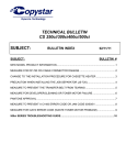
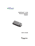
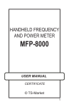
Data Acquisition Kit User Manual Document Reference: PA/AU/UM/14/04-R1.0 Data Acquisition Kit User Manual Revision History Date Revision Authors Remarks 04/04/2014 1.0 KSD, SP Initial Document Page 1 of 18 Precisol Automation India Pvt. Ltd. Data Acquisition Kit User Manual Table of Contents 1. INTRODUCTION............................................................................................................................................. 4 2. DEVICE SPECIFICATIONS ................................................................................................................................ 5 2.1 2.2 2.3 2.3.1 2.3.2 2.4 2.5 2.6 2.7 2.8 3. Analog inputs ........................................................................................................................................................ 5 Digital inputs......................................................................................................................................................... 5 Digital Outputs ..................................................................................................................................................... 5 Relay mode ....................................................................................................................................................................5 Digital switch mode.....................................................................................................................................................6 ADC characteristics ............................................................................................................................................... 6 Power ................................................................................................................................................................... 6 Operating conditions ............................................................................................................................................ 6 Software Support ................................................................................................................................................. 6 Mechanicals .......................................................................................................................................................... 7 CONNECTORS AND INDICATIONS .................................................................................................................. 8 3.1 3.2 3.2.1 3.2.2 3.3 3.4 3.5 4. Placements ........................................................................................................................................................... 8 Terminal blocks .................................................................................................................................................... 9 Top terminal connector details ...............................................................................................................................9 Bottom terminal connector details ......................................................................................................................10 LED ...................................................................................................................................................................... 10 USB connector .................................................................................................................................................... 10 Reset switch ....................................................................................................................................................... 11 INSTALLATION..............................................................................................................................................11 4.1 4.2 4.3 4.4 4.5 4.5.1 4.5.2 4.6 Mounting ............................................................................................................................................................ 11 Terminal blocks .................................................................................................................................................. 12 Analog Input connections ................................................................................................................................... 12 Digital Input connections.................................................................................................................................... 13 Digital output connections ................................................................................................................................. 14 Relay mode ...................................................................................................................................................................14 Digital switch mode...................................................................................................................................................15 Power supply ...................................................................................................................................................... 16 5. USING THE DEVICE .......................................................................................................................................16 6. FAQS ............................................................................................................................................................17 7. ORDERING INFO ...........................................................................................................................................18 8. SUPPORT......................................................................................................................................................18 8.1 8.2 8.3 Usability .............................................................................................................................................................. 18 Warranty ............................................................................................................................................................ 18 Service ................................................................................................................................................................ 18 Page 2 of 18 Precisol Automation India Pvt. Ltd. Data Acquisition Kit User Manual Table of Figures FIGURE 1: DATA ACQUISITION DEVICE APPLICATIONS ...................................................................................................................... 4 FIGURE 2: GSM RELAY CONTROLLER DIMENSIONS ........................................................................................................................ 7 FIGURE 3: DATA ACQUISITION DEVICE PLACEMENTS ....................................................................................................................... 8 FIGURE 4: DATA ACQUISITION DEVICE - TOP & BOTTOM CONNECTOR ............................................................................................. 11 FIGURE 5: ANALOG INPUTS CONNECTION................................................................................................................................... 12 FIGURE 6: DIGITAL INPUTS CONNECTION .................................................................................................................................... 13 FIGURE 7: RELAY MODE CONNECTION WITH EXTERNAL SUPPLY ....................................................................................................... 14 FIGURE 8: DIGITAL SWITCH MODE CONNECTION .......................................................................................................................... 15 FIGURE 9: USB CABLE AND CONNECTORS .................................................................................................................................. 16 Table of Tables TABLE 1: TOP TERMINAL BLOCKS DETAILS .................................................................................................................................... 9 TABLE 2: BOTTOM TERMINAL BLOCKS DETAILS ............................................................................................................................ 10 TABLE 3: STATUS LED INDICATIONS .......................................................................................................................................... 10 TABLE 4: FREQUENTLY ASKED QUESTIONS .................................................................................................................................. 17 Page 3 of 18 Precisol Automation India Pvt. Ltd. Data Acquisition Kit User Manual 1. Introduction The AUXXX series of USB Data Acquisition devices from Precisol Automation are low cost offering with functionalities available in many high end data acquisition systems. The device not only supports data acquisition but also enables control of external devices through digital output interface. AUXXX series devices are powered by a powerful microcontroller with USB device interface. There are up to 8 analog input channels available for connecting different sensors at different sampling rates and 4 digital inputs which can be programmed for different ON/OFF de-bounce timing. In addition to the analog and digital input monitoring, the device also supports up to 8 digital outputs in Relay mode or 4 digital outputs in Digital Switch mode. Each digital output can be switched on or off individually with a programmable ON duration, ON/OFF delay. Figure 1: Data Acquisition device applications Page 4 of 18 Precisol Automation India Pvt. Ltd. Data Acquisition Kit User Manual 2. Device Specifications The following section describes the device specifications 2.1 Analog inputs Number of channels : 8 Channel configuration : Differential Voltage measurement range : ±10V Full scale Input Impedance : 1MΩ Isolation : None Overall Inaccuracy : ±68mV DC common mode rejection : 70dB Max common mode voltage : ±10V Analog frequency response : -3db @ 100HZ 2.2 Digital inputs Number of channels : 4 Pull-up value : 47 KΩ Isolation : None Input high voltage threshold : ≥1.4 V Input low voltage threshold : ≤1.1 V Absolute max values : ±30 VDC 2.3 Digital Outputs Data acquisition device supports two modes of digital outputs. Digital switch mode Relay mode 2.3.1 Relay mode Number of channels : 8 Isolation : None Absolute max ratings : 40V Current : 600mA This mode is suitable when external relays are used to control the loads. The connection details of this mode of relay control are described in Section 4.5.1. Page 5 of 18 Precisol Automation India Pvt. Ltd. Data Acquisition Kit User Manual 2.3.2 Digital switch mode Number of channels : 4 Isolation : None Absolute max voltage ratings : 60 V Absolute max Current ratings : 300mA The mode of digital output is useful when the user requires to directly control the load without the external relays. The user must note that the load current must not exceed the maximum current rating. The connection details of this mode are explained in Section 4.5.2. 2.4 ADC characteristics Resolution : 16-bit Max. sample throughput rate : 10KHz 2.5 Power Voltage input : 5V input through USB interface Power Consumption : 0.50 watts : -40°C to 105°C (-40°F to 221°F ) 2.6 Operating conditions 2.7 Operating Temperature Software Support Supported software : PRISM OS support : Windows XP, Windows 7, Windows 8 Page 6 of 18 Precisol Automation India Pvt. Ltd. Data Acquisition Kit User Manual 2.8 Mechanicals Enclosure : ABS plastic Mounting : Bottom lid with flange support Dimension : 160mm x 70mm x 45mm Figure 2: GSM Relay Controller Dimensions A highly reliable enclosure made of ABS plastic is used. This enclosure supports flanges which enables the device to be mounted at a suitable place. Page 7 of 18 Precisol Automation India Pvt. Ltd. Data Acquisition Kit User Manual 3. Connectors and Indications The following sections describes about the connectors, LED used in AXXX series Data Acquisition device and their placement. 3.1 Placements Front view Side view (right) Side view (left) Figure 3: Data Acquisition device placements Page 8 of 18 Precisol Automation India Pvt. Ltd. Data Acquisition Kit User Manual 3.2 Terminal blocks The device contains two 16-pin terminal connectors at the top and bottom. The top terminal connectors are allotted for digital input, output and ground connections, whereas the bottom terminal connectors are allotted for differential analog input connections. The details of the top and bottom terminal connectors are described in the following sections. 3.2.1 Top terminal connector details Number Name Description 1 NC No connect 2 NC No connect 3 NC No connect 4 GND Device ground 5 Digital input 1 External digital input 1 signal interface 6 Digital input 2 External digital input 2 signal interface 7 Digital input 3 External digital input 3 signal interface 8 Digital input 4 External digital input 4 signal interface Relay 1 Relay Mode: Relay 1 driver or or Switch 1+ Digital Switch Mode: Positive Terminal of Switch 1 Relay 2 Relay Mode: Relay 2 driver Or or Switch 1- Digital Switch Mode: Negative Terminal of Switch 1 Relay 3 Relay Mode: Relay 3 driver or or Switch 2+ Digital Switch Mode: Positive Terminal of Switch 2 Relay 4 Relay Mode: Relay 4 driver or or Switch 2- Digital Switch Mode: Negative Terminal of Switch 2 Relay 5 Relay Mode: Relay 5 driver or or Switch 3+ Digital Switch Mode: Positive Terminal of Switch 3 Relay 6 Relay Mode: Relay 6 driver Or or Switch 3- Digital Switch Mode: Negative Terminal of Switch 3 Relay 7 Relay Mode: Relay 7 driver or or Switch 4+ Digital Switch Mode: Positive Terminal of Switch 4 Relay 8 Relay Mode: Relay 8 driver or or Switch 4- Digital Switch Mode: Negative Terminal of Switch 4 9 10 11 12 13 14 15 16 Table 1: Top Terminal Blocks details Page 9 of 18 Precisol Automation India Pvt. Ltd. Data Acquisition Kit User Manual 3.2.2 Bottom terminal connector details Number Name Description 1 Analog input 1+ Differential Analog input signal 1 positive terminal 2 Analog input 1- Differential Analog input signal 1 negative terminal 3 Analog input 2+ Differential Analog input signal 2 positive terminal 4 Analog input 2- Differential Analog input signal 2 negative terminal 5 Analog input 3+ Differential Analog input signal 3 positive terminal 6 Analog input 3- Differential Analog input signal 3 negative terminal 7 Analog input 4+ Differential Analog input signal 4 positive terminal 8 Analog input 4- Differential Analog input signal 4 negative terminal 9 Analog input 5+ Differential Analog input signal 5 positive terminal 10 Analog input 5- Differential Analog input signal 5 negative terminal 11 Analog input 6+ Differential Analog input signal 6 positive terminal 12 Analog input 6- Differential Analog input signal 6 negative terminal 13 Analog input 7+ Differential Analog input signal 7 positive terminal 14 Analog input 7- Differential Analog input signal 7 negative terminal 15 Analog input 8+ Differential Analog input signal 8 positive terminal 16 Analog input 8- Differential Analog input signal 8 negative terminal Table 2: Bottom Terminal Blocks details 3.3 LED Data acquisition device has one status LED provided for indicating status of the device. The following table describes the indications of the status LED. LED status Indication One blink Device in idle state Two blink Device connected and configured for acquisition Three blink Four blink Device acquisition and communication in progress Device in error state Table 3: Status LED indications 3.4 USB connector The standard B type female USB connector is placed as shown in the Figure 3: Data Acquisition device placements. A standard USB B male to USB A male cable can be used to interface the device with the PC for real time data acquisition. The power to the device is also supplied through the USB connector. Page 10 of 18 Precisol Automation India Pvt. Ltd. Data Acquisition Kit User Manual 3.5 Reset switch The reset switch is placed as shown in the Figure 3: Data Acquisition device placements. This switch is placed inside the enclosure to avoid the unwanted or unnoticed operation. A small opening is provided to access the switch using a non conductive or plastic material. 4. Installation The following section describes the procedure for installing the Data Acquisition device on site. The below picture depicts the connector information. Figure 4: Data Acquisition device - Top & Bottom Connector 4.1 Mounting The flange support provided in the enclosure holds four holes of 4mm diameter by which the device can be mounted horizontally or vertically as per user requirement. Page 11 of 18 Precisol Automation India Pvt. Ltd. Data Acquisition Kit User Manual 4.2 Terminal blocks The terminal block has a screw mechanism for connecting the sensor leads in the top of the enclosure and the provision for inserting the signal lead at the side of the enclosure as shown in the Figure 3: Data Acquisition device placements. Care must be taken to correctly insert the signal leads to its respective terminal blocks. The details of the terminal blocks are described in the Table 1: Top Terminal Blocks details and Table 2: Bottom Terminal Blocks details. To connect the signal leads to the terminal blocks follow the procedure, 1. Loosen the pressure flap of the terminal block by rotating the screw in the anti clockwise direction. 2. Insert the signal lead into the terminal block under the loosened pressure flap. 3. Now tighten the pressure flap by rotating the screw in the clockwise direction. 4. Tug the signal lead gently to ensure that it is connected securely. 4.3 Analog Input connections Analog input signal from any sensor can be connected to the device through the terminal connector. There are 16 terminal connectors for the differential analog inputs interface which means 8 differential paired terminal connectors. Connect the positive terminal of the analog input signal to the differential analog input positive terminal connector and connect the negative terminal to the differential analog input negative terminal connector as shown in the figure below. Figure 5: Analog Inputs Connection Page 12 of 18 Precisol Automation India Pvt. Ltd. Data Acquisition Kit User Manual 4.4 Digital Input connections Digital signal from any digital source or sensor can be connected to the device through the terminal connector. There are four terminal connectors for the digital inputs interface. Connect the positive terminal of the digital input signal to the digital input terminal connector and to close the circuit, connect the negative terminal to the device ground. The following figure depicts the digital input connection. Figure 6: Digital inputs connection Page 13 of 18 Precisol Automation India Pvt. Ltd. Data Acquisition Kit User Manual 4.5 Digital output connections Depending on the device model, either Relay mode or Digital Switch mode is supported. The following section explains connecting the load in both the modes. 4.5.1 Relay mode In this mode, the digital output is driven using a BJT. The below block diagram depicts the internal connection: For this operation, first the external supply and the device supply ground terminals must be connected together. Then the external supply can be used to power the relay as shown in the below figure. Figure 7: Relay mode connection with external supply Page 14 of 18 Precisol Automation India Pvt. Ltd. Data Acquisition Kit User Manual 4.5.2 Digital switch mode In this mode, internally a FET is used to control the digital outputs. The following diagram explains the associated internal circuitry. To use the device to control the load, the positive and negative terminals can be connected in between the load. The load can be powered by any power supply within the allowed maximum range of the FET. The following figure depicts the Digital switch mode relay connection, Figure 8: Digital Switch mode connection Page 15 of 18 Precisol Automation India Pvt. Ltd. Data Acquisition Kit User Manual 4.6 Power supply Since the device is used to acquire the real time data on PC, the device is designed to operate significantly with the power from USB interface. To power the device, just plug in the USB B male plug of the USB B male to USB A male cable shown in the below figure to the USB B female connector in the device and plug in the USB A male plug into the USB A female connector of the PC. Figure 9: USB Cable and Connectors 5. Using the device The following points listed can be used to start with the Data Acquisition device. 1. Connect the digital, analog inputs and digital output signals to the respective terminal connectors as described in the Section 4. 2. Now connect the device through USB cable to the PC where the PRISM software is already installed 3. Upon connection, the device status LED will be single blink. This indicates that the device is connected to the PC and it is in idle state, waiting for software connection and configuration. 4. Open the PRISM software, select and connect to the device. Then using the Dive View interface in PRISM, configure the data acquisition kit for necessary channels, sampling rates, accuracy etc. Up on starting the capture, the data from the inputs will be acquired by the PRISM software which may be recorded. All these captured data can be viewed using different widgets. Kindly please refer the PRISM software manual for more details on using it. 5. Upon successful configuration and connection, the device status LED will be two blink. 6. Once the PRISM software has established a communication and started acquiring the real time data through USB, the device status LED indication will be changed to three blink. 7. The device status LED indication will blink four time, if any error has been occurred in any of the processes. 8. The acquisition can be stopped and device disconnected before removing the USB cable to power off the device. Page 16 of 18 Precisol Automation India Pvt. Ltd. Data Acquisition Kit User Manual 6. FAQs Problems Troubleshoot The device led is OFF Ensure that the USB is connected properly with PC USB port. Verify 5V is present using voltmeter. The device status LED is blinking four times Fault in establishing communication between the PC and device. Kindly check with the USB cable and better to replace the cable and restart the connection procedure. Relay is not working properly There may be a fault in power section of the relay. Kindly check whether the power connection to the relay is done as described in the Section 4.5 Table 4: Frequently Asked Questions Page 17 of 18 Precisol Automation India Pvt. Ltd. Data Acquisition Kit User Manual 7. Ordering Info There are three variants in Data Acquisition device depending upon the number of digital inputs, digital outputs and analog inputs. The following table lists the variants and their configurations. Ordering code: S.No Part Number 1 AU101 2 AU111 3 AU122 Description USB data acquisition device with 4 digital inputs and 4 differential analog inputs. USB data acquisition device with 4 digital inputs, 4 digital outputs in digital switch mode and 4 differential analog inputs. USB data acquisition device with 4 digital inputs, 8 digital outputs in relay mode and 8 differential analog inputs. 8. Support 8.1 Usability Precisol Automation products are tested rigorously and are released after strict quality checks. But selection and usage of these products are the sole responsibility of the customer. Precisol Automation is not responsible for any damages to properties, environment or persons including bodily injuries, death etc. Any use of products by the customer is at the customer’s own risk. 8.2 Warranty Warranty does not extend to products that have been repaired or altered by personal not authorized by Precisol Automation or products that have been subjected to misuse, neglect, improper installation or accident. Precisol Automation shall have no liability for incidental or consequential damages of any kind arising out of the sale, installation, or use of its products. 8.3 Service Precisol Automation will repair the defective products free of cost under warranty period, with user paying the freight charges. The products that are not under warranty period will be repaired under user paid freight and repair costs. Page 18 of 18 Precisol Automation India Pvt. Ltd.