1
Table of Contents
Table of Contents ............................................................................................................... 1
Foreword ............................................................................................................................ 2
Warranty Terms ........................................................................................................................... 2
About this Instruction Manual ....................................................................................................... 3
Safety precautions ....................................................................................................................... 4
Overview of this kit ............................................................................................................ 5
Function ....................................................................................................................................... 5
Optimum engine setting ............................................................................................................ 5
Applicable models .................................................................................................................... 5
Prior to use ......................................................................................................................... 6
Items contained in this Kit. ........................................................................................................... 6
Items contained in the KX FI Calibration Kit .............................................................................. 6
Optional parts ........................................................................................................................... 8
Part names of FI Calibration Controller ........................................................................................ 9
Names and functions of the FI Calibration Controller screens .................................................... 10
Setup of FI Calibration Controller ............................................................................................... 13
Date and time setting .............................................................................................................. 13
Changing display unit ............................................................................................................. 14
Viewing the system information .............................................................................................. 14
Specifications............................................................................................................................. 15
Precautions for use .................................................................................................................... 16
Troubleshooting ......................................................................................................................... 16
Preparation ....................................................................................................................... 18
Installing the calibration kit connecting sub-harness .................................................................. 18
To obtain optimum engine control setting ..................................................................... 27
ON Line mode ........................................................................................................................... 27
Adjustment of fuel injection amount ........................................................................................ 34
Adjustment of ignition timing ................................................................................................... 38
Mapping point setting ............................................................................................................. 42
Saving the setting data ........................................................................................................... 46
Deleting the saved setting data............................................................................................... 51
Data Monitor ........................................................................................................................... 52
Resetting ECU........................................................................................................................ 53
OFF Line mode .......................................................................................................................... 54
Adjustment of fuel injection amount ........................................................................................ 56
Adjustment of ignition timing ................................................................................................... 60
Mapping point setting ............................................................................................................. 64
Saving the setting data ........................................................................................................... 68
Data management ..................................................................................................................... 74
Outline of storage locations of the setting data files ................................................................ 74
Storage location of the setting data ......................................................................................... 75
Back-up data .......................................................................................................................... 76
1
Foreword
Congratulations on your choosing KX FI Calibration Kit.
This document describes the outline and basic operation of the KX FI Calibration Kit. Read this document
carefully and understand the performance and functions of this KX FI Calibration Kit for optimum use of this
kit.
Warranty Terms
The KX series motorcycles are sold as competition racing machines and as such there is no manufacturer's
warranty expressed or implied.
You should also be aware that any abnormalities that arise due to the use of the KX FI Calibration Kit are
not warranted.
The loss of data due to the failure of hardware, malfunction or any other reason under the environment
where the KX FI Calibration Kit is used will not be covered by the Warranty. We recommend you to back-up
the data which is important for you.
The KX FI Calibration Kit will not guarantee that this kit will fit for a user's specific purpose.
The warranty will become void if the KX FI Calibration Kit is disassembled.
The failure caused by the use of the AC adapter, cable, etc. not specified for use with the KX FI Calibration
Kit is out of warranty.
The failure caused by the use of the KX FI Calibration Kit for any purpose not described in this instruction
manual is out of warranty.
2
About this Instruction Manual
For the motorcycle service information not covered by this document, refer to KX450F Service Manual
(99925-1243-01 to -03, 99925-1256-01 to -04, or 99925-1271-01) or KX250F Service Manual
(99925-1251-01 to -02, or 99925-1259-01 to -04).
This document is intended for personnel who have the basic knowledge of Windows and therefore does not
contain the explanations of the general terms and operations of the Windows.
No parts of this publication may be reproduced, stored in a retrieval system, or transmitted in any form or by
any means, electronic mechanical photocopying, recording or otherwise, without the prior written
permission of Motorcycle & Engine Company, Kawasaki Heavy Industries, Ltd.
All information contained in this document is based on the latest product information available at the time of
publication.
The specifications and design of the product and the contents of the service manual and this document
may be subject to change for product improvement without prior notice.
In this document, the following three symbols are used to distinguish the types of description.
: Indicates a procedural step or work to be done.
: Indicates a procedural sub-step or how to do the work of the procedural step it follows. It also precedes
the text of a NOTE.
: Indicates a conditional step or what action to take based on the results of the test or inspection in the
procedural step or sub-step it follows.
This document used the following warning and caution symbols to assure the safety of your inspection and
maintenance services.
WARNING
WARNING indicates a hazardous situation which, if not avoided, could result in death or serious injury.
NOTICE
NOTICE is used to address practices not related to personal injury.
NOTE
NOTE indicates information that may help or guide you in the proper operation or service of the motorcycle.
Windows Vista, Windows 7, Windows 8 and Windows 8.1 are either registered trademarks or trademarks of
Microsoft Corporation in the United States and/or other countries.
3
Safety precautions
Exhaust gas is toxic. Never operate the engine in a closed or poorly-ventilated space for a long time.
The exhaust pipe and engine are hot while operating the engine or just after stopping it. Keep your hands,
body and clothes away from them so as not to get burnt.
Fuel is highly flammable and can be explosive under certain conditions. Always stop the engine and keep
away the source of ignition when handling the fuel or refueling. This includes any appliance with a pilot light.
If too much fuel is filled in the fuel tank, it may expand during running and may flow out through the breather
hose on the tank cap.
Close the tank cap securely.
If the fuel spills, wipe it off completely with shop towel.
While servicing, be careful that your hands, clothes, or tool not to contact or be caught by wheels, drive
chain, sprockets, or other rotating or moving parts.
4
Overview of this kit
This KX FI Calibration Kit enables you to adjust the fuel injection amount and ignition timing by connecting
this to the vehicle's ECU (electronic control unit).
By repeating the change of setting, you may obtain the optimum engine setting fit for the course, weather
and rider's performance.
Function
Using this KX FI Calibration Kit, you can adjust the engine setting optimum for the course, weather and
rider's performance.
Optimum engine setting
You can change the engine setting easily using the preset setting data.
You can also create your custom data by finely adjusting the fuel injection amount and ignition timing. This
custom data can be stored in the Calibration Kit. By selecting and applying a suitable data in your custom data
list, you can cope with various riding situations.
Applicable models
Common name
KX250F
KX450F
Year
Model
2011
2012
2013
2014
2015
2016
2009
2010
2011
2012
2013
2014
2015
2016
KX250YB
KX250YC
KX250ZD
KX250ZE
KX250ZF
KX250ZG
KX450E9
KX450EA
KX450EB
KX450FC
KX450FD
KX450FE
KX450FF
KX450HG
Require additional options
Sub-harness
Bracket
26011-0315
11056-0587
26011-0315
11056-1657
26011-0933
11056-0505
26011-0933
11056-0505
26011-0933
11056-0505
26011-0933
11056-0505
26011-0933
11056-0505
26011-0933
11056-0505
26011-0315
11056-0597
26011-0933
11056-0505
26011-0933
11056-0505
26011-0933
11056-0505
26011-0933
11056-0505
26011-0933
11056-0505
5
Prior to use
This section contains the information you should know prior to use the KX FI Calibration Kit.
Items contained in this Kit.
Items contained in the KX FI Calibration Kit
No.
1
2
3
4
5
6
7
8
Q’ty
1
1
1
1
1
Part name
FI Calibration Controller
SD Memory Card
Carrying Box
Controller Transfer Cable
Vehicle Transfer Cable
AC Adapter (Other than EU [A], EU [B])
1
CD-ROM (Contains Instruction Manual, Quick
Reference Sheet, Back-up Data of SD Memory Card)
Quick Reference Sheet
6
1
1
Remarks
2GB
P/No. 26011-0940
P/No. 26011-0941
P/No. 41077-0726 (Other than EU) [A]
P/No. 41077-0727 (EU) [B]
P/No. 41080-0665
7
Optional parts
No.
1
2
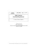
Part name
Calibration kit connecting sub-harness
Diagnosis connector bracket
8
Part names of FI Calibration Controller
Display [A]
Up Button [B]
Left Button [C]
OK Button (Power Button) [D]
Right Button [E]
Down Button [F]
Cancel Button [G]
F1 Button [H]
F2 Button [I]
F3 Button [J]
F4 Button [K]
Red Battery Charging Indicator [L]
Orange Communication indicator [M]
Controller Transfer Cable Connector [A]
USB Hi-Speed Cable Connector [A]
Reset Button [B]
SD Memory Card [C]
NOTE
Do not use the USB hi-speed cable connector.
FI Calibration Controller Battery Charging Connector [A]
9
Names and functions of the FI Calibration Controller screens
This section explains the names and functions of the screens of the FI Calibration Controller.
Turning on the Controller
To turn on the FI Calibration Controller, press the OK button
for 2 seconds or longer.
To turn off, press the OK button for 2 seconds or longer.
NOTE
Be sure to charge the battery of the Controller sufficiently
before use.
If the battery runs down during operation, data is not updated.
Major functions
Pressing the OK button displays the mode selection screen.
There are three modes in the FI Calibration Controller.
OFF Line For editing the setting data without connecting the
Controller to the motorcycle.
ON Line
For operation with the Controller connected to the
motorcycle - editing of setting data and writing the
setting in ECU.
Setup
For adjusting clock, changing unit of display, and
viewing system information.
Each mode can be selected by pressing F1, F2 or F3 button.
The date, time and battery remaining power are displayed at
the top right of the display.
Examples of typical operations
Rewriting of ECU data using a preset setting data (On Line
mode: With the Controller connected to the motorcycle).
The following can be performed.
To rewrite the fuel injection amount setting
To rewrite the ignition timing setting
To change the mapping points (area where you are to
adjust the setting, defined by engine speed and throttle
opening)
To save the setting data in file format.
Preparing setting data in advance (Off Line mode: With the
Controller not connected to the motorcycle). The following
can be performed.
To change the fuel injection amount setting.
To change the ignition timing setting.
To change the mapping points (area where you are to
adjust the setting, defined by engine speed and throttle
opening)
To save the setting data in a file.
Viewing the current engine condition (On Line mode)
Resetting ECU to the factory setting (On Line mode)
10
Name of the screen and functions
11
12
Setup of FI Calibration Controller
The setup function is used to change the date and time, and
displayed units. It is also used to view the system information.
Press the F3 button at the mode selection screen.
At the Setup screen, press the F1, F2 or F3 button to select
the setting item.
Date/Time Setting
For setting date and time
deg C/deg F
For selecting display unit
System Information
For viewing the system information
Date and time setting
Press the F1 button at the setup screen.
Move the cursor using left or right button and select the item
to be changed by pressing the OK button.
Change the figure using the up or down button and press the
OK button to confirm it.
After setting, press the F4 button to apply the setting.
The display returns to the Setup screen.
13
Changing display unit
Press the F2 button at the setup screen.
Press the F1 button to select the celcius (C) unit, or press the
F2 button to select the fahrenheit (F) unit.
After changing the unit, pressing the Cancel button returns the
display to the Setup screen.
Viewing the system information
Press the F3 button at the setup screen.
The system information is displayed.
Interface S/N
Serial number of the Controller
FW Version
Version of firmware
SW Version
Version of data in the SD memory card
NOTE
The serial number is also indicated at the back of the
Controller.
Pressing the Cancel button returns the display to the setup
screen.
14
Specifications
FI Calibration Controller
Dimension
L: 173.78 mm (6.8417 in.)
W: 134.66 mm (5.3016 in.)
H: 60.91 mm (2.3980 in.)
AC Adapter
Input: 100 ~ 240V, Output: DC 18V
Operating Voltage
DC 8 ~ 18 V
Operating Current
300 mA
Operating Temperature
0C 70C (32 158 F)
Dust and Water
IP55
Resistance
The red battery charging indicator illuminates while charging
the battery in the Controller.
The remaining battery power is indicated on the display: 100 45%: Green; 44 - 30%: Yellow; 29% or lower: Red
When the remaining battery power lowers below 20%, buzzer
sounds for 5 seconds. When it lowers to 10% and 5%, buzzer
sounds for 10 seconds respectively.
The Controller automatically shuts down if not operated for 5
minutes.
The orange communication indicator illuminates when the
Controller is connected to the motorcycle.
The waterproof performance of the Controller is
water-resistant for daily ordinary use (with caps are closed
securely).
Personal computer
A personal computer is used to view the instruction manual and
the quick reference sheet data, and to copy the back-up data
into the SD memory card.
Item
OS
Others
Details
Windows 8.1/8/7/Vista
CD-ROM drive: Required to view the instruction
manual and quick reference sheet. Also required to
copy the back-up data to the SD memory card.
SD memory card reader: Required to copy the
back-up data from the CD-ROM.
Adobe Reader: Required to view PDF files
(instruction manual and quick reference sheet).
15
Precautions for use
Do not connect the FI Calibration Controller to the motorcycle
during charging the Controller.
Do not remove the SD memory card while operating the
Controller.
Use the SD memory card 2 GB or lower in size. (Do not use
the SDHC, SDXC or UHS memory card.)
Up to 200 settings can be stored in a SD memory card. If the
number of settings exceeds 200, the oldest setting will be
deleted when a new (201th) setting is saved. Therefore, copy
the data in a personal computer as necessary.
If the capacitor is faulty or capacitor connector is
disconnected, the On Line mode adjustment cannot be
performed. Replace the capacitor or reconnect the connector.
(Refer to Service Manual.)
If the charge warning buzzer sounds, charge the Controller in
the earliest opportunity. (The buzzer sounds when the battery
remaining power becomes 20%, 10% and 5%.)
Be sure to use the AC adapter included in the kit.
Never disassemble the FI Calibration Controller.
Do not drop the FI Calibration Controller.
Keep the FI Calibration Controller away from water.
Troubleshooting
If the warning shown in the drawing appears on the display,
remove and reinsert the SD memory card, then push the reset
button to reboot.
If the communication breaks while the Controller is connected
to the motorcycle (On Line mode), the warning shown in the
drawing appears. Push the OK button or Cancel button to
return to the Menu screen, and check the connection
condition of the cable.
16
If the Controller freezes and would not accept any operation,
push the reset button [A] with a thin rod to reboot.
17
Preparation
It is necessary to install the calibration kit connecting sub-harness to the motorcycle before using the KX FI
Calibration Kit.
Installing the calibration kit connecting sub-harness
To use the KX FI Calibration Kit, installation of some optional
parts of the motorcycle listed in the table on page 5 are required.
Be sure to prepare these parts.
KX450F (2016 model)
Remove:
Band [B] of the number plate [A]
Number plate bolt [C]
Clear the number plate from the projections [D] on the
steering stem base.
Remove:
Bracket bolt [A]
Bracket [B]
Remove the Kawasaki diagnostic system connector [C] from
the bracket.
Install the diagnosis connector bracket [A] and tighten the
bracket bolt [B].
Torque - Bracket bolt: 5.0 Nm (0.51 kgfm, 44 inlb)
Install the Kawasaki diagnostic system connector [C] to the
diagnosis connector bracket.
Remove: (Left side only)
Side Cover Bolt [A]
Radiator Shroud Bolt [B]
Seat Bolt [C]
18
Pull the side cover [A] upward to clear the hooks [B] and
remove the side cover.
Remove: (Left side only)
Radiator Shroud Bolts [A]
Radiator Shroud [B]
Remove the cap [A] from the connector for KX FI Calibration
Kit.
NOTE
Store the connector cap as it will not be used.
Open the clamp [B] to free the harness [C] and refit the clamp.
Connect the calibration kit connecting sub-harness [A] to the
connector for calibration kit. Route the sub-harness along the
main harness [B].
Secure the sub-harness with the clamp [C].
Position the connector [D] under the frame.
Route the calibration kit connecting sub-harness inside the
engine stop switch lead wire.
Engine Stop Switch Lead Wire Connector [E]
19
Install the connector [A] of the calibration kit connecting
sub-harness to the diagnosis connector bracket.
Install the radiator shroud [A].
Tighten the radiator shroud bolts.
L = 9 mm (0.35 in.) [B]
L = 14 mm (0.55 in.) [C]
L = 20 mm (0.79 in.) [D]
Torque - Radiator Shroud Bolt: 7.0 Nm (0.71 kgfm, 62
inlb)
Insert the hooks [B] of the side cover [A] with the ribs [D] of
the radiator shroud [C].
Tighten:
Torque - Side Cover Bolt [A]: 7.0 Nm (0.71 kgfm, 62
inlb)
Radiator Shroud Bolt [B]: 7.0 Nm (0.71 kgfm,
62 inlb)
Seat Bolt [C]: 25 Nm (2.5 kgfm, 18 ftlb)
Fit the holes [A] of the number plate over the projections [B]
on the steering stem base.
Run the brake hose in front of the number plate.
Fit the band of the number plate over the handlebar pad and
tighten the number plate bolt.
Torque - Number Plate Bolt: 8.0 Nm (0.82 kgfm, 71 inlb)
NOTE
Be sure to turn the handlebar fully right and left to confirm that
it turns smoothly without binding.
20
KX250F (2016 model)
Remove:
Band [A] of the number plate [B]
Number plate bolt [C]
Clear the number plate from the projections [D] on the
steering stem base.
Remove:
Bracket Bolt [A]
Bracket [B]
Remove the Kawasaki diagnostic system connector [C] from
the bracket.
Install the diagnosis connector bracket [A] and tighten the
bracket bolt [B].
Install the Kawasaki diagnostic system connector [C] to the
diagnosis connector bracket.
Remove the side cover bolts [A] on both sides.
Spread the side covers lightly [A].
Pull and remove the seat [B] toward the rear [C].
21
Remove:
Bolt [A]
Radiator Shroud [B]
Clear the tabs [C] of the radiator shroud from the air cleaner
housing.
Remove.
Fuel Tank Bolt [A]
Band [B]
Draw the fuel out from the fuel tank with a commercially
available fuel pump [A].
Use a soft plastic hose [B] as a pump intake hose in order to
insert the hose smoothly.
Put the hose through the fill opening [C] into the tank and
draw the fuel out.
WARNING
Spilled fuel is flammable and can be explosive under certain
conditions. The fuel can not be removed completely from the
fuel tank. Be careful for remained fuel spillage.
Close the fuel tank cap.
Lift up the fuel tank, and disconnect the fuel pump lead
connector [A].
Be sure to place a piece of cloth around the fuel hose joint.
Wipe off the dirt of the surface [A] around the connection
using a cloth or a soft brush.
22
Insert the standard tip screwdriver [A] into the slit [B] on the
joint lock [C].
Turn the driver to disconnect the joint lock.
Disconnect the fuel hose joint [A] from the fuel outlet pipe.
WARNING
Fuel is flammable and explosive under certain conditions and
can cause severe burns. Be prepared for fuel spillage; any
spilled fuel must be completely wiped up immediately. When
the fuel hose is disconnected, fuel spills out from the hose and
the pipe because of residual pressure. Cover the hose
connection with a piece of clean cloth to prevent fuel spillage.
Remove the fuel tank, and place a it on a flat surface.
NOTE
Do not apply the load to the fuel outlet pipe of the fuel pump.
WARNING
Gasoline is extremely flammable and can be explosive under
certain conditions, creating the potential for serious burns.
Store the fuel tank in an area which is well-ventilated and free
from any source of flame or sparks. Do not smoke in this area.
Place the fuel tank on a flat surface and plug the fuel pipes
to prevent fuel leakage.
Clean the pipe [A].
Cover the pipe and hose joint [B] with plastic bags [C] to keep
them clean.
Unwind the tape [A].
Remove the cap [B] from the connector for KX FI Calibration
Kit.
Connect the calibration kit connecting sub-harness to the
connector and run the sub-harness along the main harness.
23
Install the connector [A] of the calibration kit connecting
sub-harness on the diagnostic connector bracket.
Run the fuel hoses correctly. (Refer to the Service Manual.)
Confirm that the dampers [A] are in place on the frame.
Remove the vinyl bags on the pipe and hose joint.
Check that there are no flaws, burrs, and adhesion of foreign
materials on fuel outlet pipe [A].
Check the joint lock for deformation and wear.
If the joint lock is deformed, replace the fuel hose with a new
one.
Apply engine oil to the fuel outlet pipe lightly.
Insert [A] the fuel hose joint [B] straight onto the fuel outlet
pipe until the hose joint clicks.
Push [C] the joint lock [D].
Push and pull [A] the fuel hose joint back and forth more than
two times, and make sure it is locked and does not come off.
WARNING
Leaking fuel can cause a fire or explosion resulting in serious
burns. Make sure the hose joint is installed correctly on the
delivery pipe by sliding the joint.
If it comes off, reinstall the hose joint.
Connect the fuel pump lead connector.
24
Hook the band to the fuel tank.
Tighten the fuel tank bolt.
After installing the fuel tank, make sure that both throttle
cables [A] (outer) move slightly by pulling them back and forth
in the upper space of the right side of the fuel tank [B]. Check
that both throttle cables run under the frame (right side) [C].
NOTE
Check the fuel hose position. If the fuel hose interferes with
the cylinder head cover, move the fuel hose upward.
Install the radiator shroud.
Insert the tabs [A] of the radiator shroud into the slots [B] of
the air cleaner housing.
Tighten the radiator shroud bolts in the order of [1] to [4].
L = 13 mm (0.51 in.) [1 to 3]
L = 20 mm (0.79 in.) [4]
Install the seat.
Insert the hooks [A] of the seat under the flange collar [B] and
brackets [C].
Take care not to damage the side covers with the bracket of
seat.
Tighten the side cover bolts.
25
Fit the holes [A] in the number plate over the projections [B]
on the steering stem base.
Run the brake hose in front of the number plate.
Fit the band of the number plate over the handlebar pad and
tighten the number plate bolt.
NOTE
Be sure to turn the handlebar fully right and left to confirm that
it turns smoothly without binding.
If the engine starting difficulty, connect the 12 V battery to the
main harness (Refer to Service Manual (Self-diagnosis
Procedures in the Fuel System (DFI) chapter)).
When the battery is connected, the fuel pump is driven and
the pressure of the fuel line increases.
26
To obtain optimum engine control setting
ON Line mode
By connecting the FI Calibration Controller to the motorcycle (On Line mode), you can change or edit the
setting data in ECU or write a prepared data into ECU.
Connecting the FI Calibration Controller to the motorcycle
NOTE
To connect the FI Calibration Kit to the motorcycle, it is
necessary to install the calibration kit connecting sub-harness
(sold separately) to the motorcycle. (For details, refer to
“Installing the calibration kit connecting sub-harness” on page
18.)
Connect the FI Calibration Controller and the motorcycle by
the following procedure.
NOTE
Be sure to charge the battery of the Controller sufficiently
before use.
Do not connect the Controller to the motorcycle while
charging its battery.
Confirm that the SD memory card is in the slot before turning
on the Controller. Do not remove the SD memory card while
operating the Controller.
Connect the controller transfer cable [A] to the controller
transfer cable connector on the Controller.
Connect the vehicle transfer cable [B] to the controller transfer
cable.
NOTE
Tighten the connecting screws of the connectors securely.
Unlock the band [A] of the number plate [B].
Remove the number plate bolt [C].
Clear the number plate from the projections [D] on the
steering stem base.
Remove the connector [B] of the calibration kit connecting
sub-harness from the diagnosis connector bracket [A] and
remove the cap from the connector.
Connect the vehicle transfer cable to the connector of the
calibration kit connecting sub-harness.
27
Turn on the Controller.
The orange launch control mode indicator light (LED) of the
motorcycle illuminates and then goes off.
At the mode selection screen, press the F2 button.
If the cable connection is faulty, the warning shown in the
drawing will appear.
Reconnect the cables properly and press OK button or press
the Cancel button to return to the mode selection screen.
Using a stored setting data as it is
* If you are going to perform setting for the first time, start from
this procedure.
This procedure is to write a stored data (sample data or
previously saved setting data) into ECU as it is.
Perform the procedure following the steps of this text while
referring to the flowchart shown below.
The following description is to use a sample data. The
procedure to use a user library data is almost the same.
28
29
Turn on the FI Calibration Controller.
The orange launch control mode indicator light (LED) of the
motorcycle illuminates and then goes off.
At the Mode selection screen press the F2 button.
NOTE
On 2013 and after KX450F models, the model selection
screen appears. Select your motorcycle model and press the
OK button.
The vehicle information will be displayed as shown in the
drawing, and the orange communication indicator will
illuminate.
Press the OK button and display the function select screen.
Press the F1 button at the function select screen.
Press F1 button to select Sample setting.
Sample
To select a preset recommended setting data.
User Library
To select one of the previously saved setting
data.
Use a sample setting when you perform setting for the first
time.
The procedure to use a setting data in the User Library is the
same.
30
Read the description of each setting data in the following
sample data table and select a setting data to be used.
<Sample Date Table>
No.
Setting data
Description
Advanced Ignition
The ignition timing is advanced by
1
Setting
3° from the standard setting.
Fuel injection amount is increased
2
Beginner
and the ignition timing is retarded
to suppress the engine output.
An example of setting for hard and
slippery surface (with bad traction).
Hard Riding
3
Fuel injection amount is increased
Surface
and the ignition timing is retarded
for better traction.
Leaner Fuel
Fuel injection amount is decreased
4
Setting
by 5% from the standard setting.
Retarded Ignition
The ignition timing is retarded by 3°
5
Setting
from the standard setting.
Richer Fuel
Fuel injection amount is increased
6
Setting
by 5% from the standard setting.
An example of setting for soft
surface like sands (with good
Soft Riding
7
traction). Fuel injection amount and
Surface
the ignition timing are adjusted to
obtain optimum power output.
NOTE
It is recommended to ride and feel the difference between the
standard and changed settings. For fuel injection amount, try
the standard, No. 4 and No. 6 settings. For ignition timing, try
the standard, No. 1 and No. 5 settings.
From the standard and No. 1, 4, 5 and 6 settings, combine the
settings for the specific ranges (defined by engine speed and
throttle opening) which you feel better, and perform fine
adjustment to obtain the setting you feel best. For a range you
felt worse, it is recommended to return the setting of that
range to the former one and retry.
No. 3 and 7 are examples of settings for different surface
conditions. Each setting is just an example and you may not
obtain your expected performance from it depending on the
situations.
No. 2 is a setting where engine output is suppressed
intentionally for beginners.
Select one of the settings using the Up or Down button and
press the OK button.
31
Map adjustment screen is displayed.
Press the F1, F2 or F3 button to select the item to be
adjusted.
F1: Fuel injection amount
F2: Ignition timing
F3: Setting of mapping point
NOTE
The setting data edit screen of the selected setting data is
displayed when F1, F2 or F3 button is pressed. Even the
selected setting data is to be used as it is, it is necessary to
select this screen.
The current data (ECU DATA) of the item selected in the
previous step is displayed in the edit screen.
Pressing the F2 button displays the selected sample setting
data.
NOTE
To write the selected setting data into ECU, refer to "Using the
registered setting data after editing" on page 33.
Pressing the F4 button writes the displayed data into ECU.
The display returns to the Map adjustment screen when
writing into ECU has completed.
32
To finish the operation, press the Cancel button to return to
the previous screen.
NOTE
If the Cancel button is pressed at Map adjustment screen, the
message shown in the drawing appears.
Pressing the F1 button returns the display to the Setting
selection screen.
Pressing the F2 button returns the display to the Map
adjustment screen.
To save the setting data written in ECU, refer to "Saving the
setting data" on page 46.
Using the registered setting data after editing
You can use a sample setting data or a previously-saved setting
data after editing its fuel injection amount and ignition timing
mapping specified by throttle opening and engine speed.
Turn on the FI Calibration Controller.
The orange launch control mode indicator light (LED) of the
motorcycle illuminates and then goes off.
At the Mode selection screen, press the F2 button.
NOTE
On 2013 and after KX450F models, the Model selection
screen appears. Select your motorcycle model and press the
OK button.
The vehicle information will be displayed as shown in the
drawing, and the orange communication indicator will
illuminate.
Press the OK button to display the Function select screen.
33
Press the F1 button at the Function select screen.
Select which type of data is to be used as a base setting data.
NOTE
Sample
To select a preset recommended setting data.
User Library
To select one of the previously saved setting
data.
Press F1 or F2 button to select the type of data to be used.
The following description uses a sample data as an example.
Select one of the settings using the Up or Down button and
press the OK button.
For details of the sample data, refer to "Sample Data Table"
on page 31.
Map adjustment screen appears.
Press the F1, F2 or F3 button to select the item to be
adjusted.
F1: Fuel injection amount (Refer to p. 34.)
F2: Ignition timing (Refer to p. 38.)
F3: Setting the mapping points (Refer to p. 42.)
Adjustment of fuel injection amount
The fuel injection amount can be increased/decreased (by %)
for each mapping point specified by engine speed and throttle
opening.
Perform the procedure following the steps of this text while
referring to the flowchart shown below. The following description
is to use a sample data. The procedure to use a user library data
is almost the same.
34
35
Press the F1 button at the Map adjustment screen.
The current setting data (FI ECU DATA) is displayed in the
setting data edit screen.
Pressing the F2 button displays the selected setting data.
NOTE
Entering the F2 EDIT DATA mode enables the editing of data.
<Data editing screen>
36
<Operation in data editing screen>
①
②
③
④
⑤
⑥
Pressing the Up button moves the cursor upward.
Pressing the Right button moves the cursor rightward.
Pressing the OK button confirms the selection of the item on the cursor.
Pressing the Up button increases the value.
Pressing the Down button decreases the value.
Pressing the OK button confirms the selection of the current value.
NOTE
The adjustable range of the Controller is 50 (%). However, if
the input data exceeds the applicable setting range of ECU,
the value within the latter range is applied. For example, if
"+45" is selected while the setting range of ECU is +20 to -10,
background of the map sheet changes to red and the value
"+20" is applied.
The applicable setting range of ECU is +20 to -10 (%).
The background colors of the map sheet (cell) are defined as
follows.
Color
Definition
White The value unchanged.
Yellow The value changed from the original setting value.
Red
The value exceeding the setting range of ECU.
37
After editing, pressing the F4 button writes the edited setting
data into ECU.
The display returns to the Map adjustment screen when the
writing into ECU has completed.
To continue editing of the setting data, or to save the data,
press the F2, F3 or F4 button.
F2: Adjusting the ignition timing of the same data setting
(Refer to p. 38.)
F3: Changing the mapping points (Refer to p. 42.)
F4: Saving the data into SD memory card (Refer to p. 46.)
NOTE
If the Cancel button is pressed at Map adjustment screen, the
message shown in the drawing appears.
Pressing the F1 button discards the current setting data and
returns the display to the Setting selection screen.
Pressing the F2 button returns the display to the Map
adjustment screen.
To save the setting data written in ECU, refer to "Saving the
setting data" on page 46.
Adjustment of ignition timing
The ignition timing can be advanced/retarded (by degree) for
each mapping point specified by engine speed and throttle
opening.
Perform the procedure following the steps of this text while
referring to the flowchart shown below. The following description
is to use a sample data. The procedure to use a user library data
is almost the same.
38
39
Press the F2 button at the Map adjustment screen.
The current setting data (IG ECU DATA) is displayed in the
setting data edit screen.
Pressing the F2 button displays the selected setting data.
NOTE
Entering the F2 EDIT DATA mode enables the editing of data.
<Data editing screen>
40
<Operation in data editing screen>
①
②
③
④
⑤
⑥
Pressing the Up button moves the cursor upward.
Pressing the Right button moves the cursor rightward.
Pressing the OK button confirms the selection of the item on the cursor.
Pressing the Up button increases the value.
Pressing the Down button decreases the value.
Pressing the OK button confirms the selection of the current value.
NOTE
The adjustable range of the Controller is 12.0 (deg).
However, if the input data exceeds the applicable setting
range of ECU, the value within the latter range is applied. For
example, if "+10.0" is selected while the setting range of ECU
is +3 to -10, background of the map sheet changes to red and
the value "+3" is applied.
The applicable setting range of ECU is +3 to -10 (deg).
The background colors of the map sheet (cell) are defined as
follows.
Color
Definition
White The value unchanged.
Yellow The value changed from the original setting value.
Red
The value exceeding the setting range of ECU.
41
After editing, pressing the F4 button writes the edited setting
data into ECU.
The display returns to the Map adjustment screen when the
writing into ECU has completed.
To continue editing of the setting data, or to save the data,
press the F1, F3 or F4 button.
F1: Adjusting the fuel injection amount of the same data
setting (Refer to p. 34.)
F3: Changing the mapping points (Refer to p. 42.)
F4: Saving the data into SD memory card (Refer to p. 46.)
NOTE
If the Cancel button is pressed at Map adjustment screen, the
message shown in the drawing appears.
Pressing the F1 button discards the current setting data and
returns the display to the Setting selection screen.
Pressing the F2 button returns the display to the Map
adjustment screen.
To save the setting data written in ECU, refer to "Saving the
setting data" on page 46.
Mapping point setting
The mapping points specified by engine speed and throttle
opening for adjustment of fuel injection amount and ignition
timing can be changed.
Perform the procedure following the steps of this text while
referring to the flowchart shown below. The following description
is to use a sample data. The procedure to use a user library data
is almost the same.
42
43
Press the F3 button at the Map adjustment screen.
The current setting data (MAP Point Setting) is displayed in
the setting data edit screen.
Pressing the F2 button displays the selected setting data.
NOTE
Entering the F2 EDIT DATA mode enables the editing of data.
<Data editing screen>
44
<Operation in data editing screen>
45
①
②
③
④
⑤
⑥
⑦
⑧
⑨
Pressing the Right button moves the cursor rightward.
Pressing the Left button moves the cursor leftward.
Pressing the left button cursor is moved to the vertical axis.
Pressing the Down button moves the cursor downward.
Pressing the Up button moves the cursor upward.
Pressing the OK button confirms the selection of the item on the cursor.
Pressing the Up button increases the value.
Pressing the Down button decreases the value.
Pressing the OK button confirms the selection of the current value.
NOTE
The setting of the fuel injection amount is based on two
variables - throttle opening and engine speed, whereas the
setting of the carburetor is only based on the throttle opening.
This enables finer setting for the fuel injection system.
After editing, pressing the F4 button writes the edited setting
data into ECU.
The display returns to the Map adjustment screen when the
writing into ECU has completed.
To continue editing of the setting data, or to save the data,
press the F1, F2 or F4 button.
F1: Adjusting the fuel injection amount of the same data
setting (Refer to p. 34.)
F2: Adjusting the ignition timing of the same data setting
(Refer to p. 38.)
F4: Saving the data into SD memory card (Refer to p. 46.)
NOTE
If the Cancel button is pressed at Map adjustment screen, the
message shown in the drawing appears.
Pressing the F1 button discards the current setting data and
returns the display to the Setting selection screen.
Pressing the F2 button returns the display to the Map
adjustment screen.
To save the setting data written in ECU, refer to "Saving the
setting data" on page 46.
Saving the setting data
The setting data edited in the fuel injection amount or ignition
timing adjustment screen can be saved in the Calibration
Controller.
Perform the procedure following the steps of this text while
referring to the flowchart shown below. The following description
is to use a sample data. The procedure to use a user library data
is almost the same.
46
47
After editing, press the F4 button at the Map adjustment
screen.
The Memo Information screen appears. You can write the
surface condition, weather, etc. in the value column to save it
together with the setting data.
<Memo Information screen>
48
<Operation in Memo Information screen>
①
②
③
④
Pressing the Down button moves the cursor downward.
Pressing the OK button confirms the selection of the item on the cursor.
Pressing the Down button moves the cursor downward.
Pressing the OK button confirms the selection.
49
①
②
③
④
⑤
⑥
⑦
⑧
⑨
⑩
⑪
Pressing the Down button moves the cursor downward.
Pressing the OK button confirms the selection of the item on the cursor.
Pressing the Right button moves the cursor rightward.
Pressing the OK button confirms the selection of the item on the cursor.
Pressing the Down button changes the value to “-“(minus) value.
Pressing the OK button confirms the selection.
Pressing the Right button moves the cursor rightward.
Pressing the OK button confirms the selection of the item on the cursor.
Pressing the Up button increases the value.
Pressing the OK button confirms the selection.
Pressing the F4 button saves the memo information and changes the display to File name edit screen.
Pressing the F4 button stores the information and the screen
changes to the File name edit screen.
NOTE
For the setting data stored in the User Library, you can
overwrite the data (Save) or save as another data (Save as).
Select either of the following:
F3 button: Save
F4 button: Save as
50
NOTE
If the Cancel button is pressed at Memo Information screen,
the message shown in the drawing appears.
Pressing the F1 button returns the display to the Memo
Information screen.
Pressing the F2 button discards the edited data and returns
the display to the Mode selection screen.
Edit the file name. Pressing the F4 button saves the setting
data.
<How to input>
Select a letter to be entered using the cursor keys and press the
OK button.
<Icons>
"Backspace" icon
Deletes a letter which is one space before the cursor.
"Shift" icon
Shifts the upper and lower cases of the alphabet.
"Space" icon
Inputs one space.
NOTE
The following symbols cannot be used in the file name.
"/"
"."
"<"
">"
"
"
The file name should be an easily-understandable one.
For example, the following file name includes date, purpose,
and creator of the file.
Ex) "150505-RainTest-Kawasaki.KSD": This file was created
on May 5, 2015, for rain test, by Mr. Kawasaki.
You can identify the similar files by adding a letter "b", "c" or
the like at the end of the date.
Ex) "150505b-RainTest-Kawasaki.KSD"
The file has been saved if the message shown in the drawing
appears.
NOTE
The file is saved in the "User Library".
Ride with the edited setting data and readjust as necessary.
Deleting the saved setting data
The setting data saved in the FI Calibration Controller can be
deleted.
51
To delete the saved setting data in the FI Calibration
Controller, select the User Library mode.
Press the F2 button to select the User Library mode.
Use the Up or Down button to select a setting data to be
deleted.
Pressing the F1 button deletes the selected setting.
Pressing the F2 button opens the Memo Information screen.
To edit the information, refer to "Saving the setting data" on
page 46.
Pressing the OK button displays the Map adjustment screen.
To edit the selected setting data, refer to "Using the registered
setting data after editing" on page 33.
Data Monitor
The status of the engine to which the Controller is connected is
displayed.
Press the F2 button at the Function select screen.
The Data monitor screen appears and the numeric data of the
engine to which the Controller is connected is shown in the
value column.
NOTE
The MAP number is displayed only for the models with DFI
setting data selection connector.
The connector numbers and colors are as follows.
MAP_No.1 ··· Green
MAP_No.2 ··· Black
MAP_No.3 ··· White
52
<Operation in Data Monitor screen>
① Pressing the Down button moves the cursor downward.
② Pressing the Cancel button returns the display to the Function select screen.
Resetting ECU
ECU to which the Controller is connected can be reset to the
factory setting.
●Press the F3 button at the Function select screen.
To perform resetting of ECU, press the F1 button. To cancel,
press the F2 button.
NOTE
By resetting, ECU returns to the factory setting.
On models with DFI setting data selection connector, if
resetting is performed when the factory-set "soft surface" or
"hard surface" setting data is selected, its values will all
become "0" ("standard surface" setting).
To return them to the factory-set "soft surface" or "hard
surface" values, use the sample setting data for that model.
53
OFF Line mode
The OFF Line mode of the FI Calibration Controller is to edit the setting data without connecting it to the
motorcycle.
Turn on the FI Calibration Controller.
Press the F1 button at the Mode selection screen.
NOTE
No connection of cable to the motorcycle is required.
Select your motorcycle model using Up or Down button and
press the OK button.
NOTE
Pressing the Cancel button returns the display to the Mode
selection screen.
Select which type of data is to be used as a base setting data.
NOTE
Sample
To select a preset recommended setting data.
User Library
To select one of the previously saved setting
data.
Press F1 or F2 button to select the type of data to be used.
The following description uses a sample data as an example.
54
Read the description of each setting data in the following
sample data table and select a setting data to be used.
<Sample Date Table>
No.
Setting data
1
Advanced Ignition
Setting
2
Beginner
3
Hard Riding Surface
4
Leaner Fuel Setting
5
Retarded Ignition
Setting
6
Richer Fuel Setting
7
Soft Riding Surface
Description
The ignition timing is advanced
by 3° from the standard
setting.
Fuel injection amount is
increased and the ignition
timing is retarded to suppress
the engine output.
An example of setting for hard
and slippery surface (with bad
traction). Fuel injection amount
is increased and the ignition
timing is retarded for better
traction.
Fuel injection amount is
decreased by 5% from the
standard setting.
The ignition timing is retarded
by 3° from the standard
setting.
Fuel injection amount is
increased by 5% from the
standard setting.
An example of setting for soft
surface like sands (with good
traction). Fuel injection amount
and the ignition timing are
adjusted to obtain optimum
power output.
NOTE
It is recommended to ride and feel the difference between the
standard and changed settings. For fuel injection amount, try
the standard, No. 4 and No. 6 settings. For ignition timing, try
the standard, No. 1 and No. 5 settings.
From the standard and No. 1, 4, 5 and 6 settings, combine the
settings for the specific ranges (defined by engine speed and
throttle opening) which you feel better, and perform fine
adjustment to obtain the setting you feel best. For a range you
felt worse, it is recommended to return the setting of that
range to the former one and retry.
No. 3 and 7 are examples of settings for different surface
conditions. Each setting is just an example and you may not
obtain your expected performance from it depending on the
situations.
No. 2 is a setting where engine output is suppressed
intentionally for beginners.
Select one of the settings using the Up or Down button and
press the OK button.
55
Map adjustment screen is displayed.
Press the F1, F2 or F3 button to select the item to be
adjusted.
F1: Fuel injection amount (Refer to p. 56.)
F2: Ignition timing (Refer to p. 60.)
F3: Setting the mapping points (Refer to p. 64.)
Adjustment of fuel injection amount
The fuel injection amount can be increased/decreased (by %)
for each mapping point specified by engine speed and throttle
opening.
Perform the procedure following the steps of this text while
referring to the flowchart shown below. The following description
is to use a sample data. The procedure to use a user library data
is almost the same.
56
Press the F1 button at the Map adjustment screen.
57
The fuel injection amount adjustment screen (FI EDIT DATA)
appears.
<Data editing screen>
58
<Operation in data editing screen>
①
②
③
④
⑤
⑥
Pressing the Up button moves the cursor upward.
Pressing the Right button moves the cursor rightward.
Pressing the OK button confirms the selection of the item on the cursor.
Pressing the Up button increases the value.
Pressing the Down button decreases the value.
Pressing the OK button confirms the selection of the current value.
NOTE
The adjustable range of the Controller is 50 (%). However, if
the input data exceeds the applicable setting range of ECU,
the value within the latter range is applied. For example, if
"+45" is selected while the setting range of ECU is +20 to -10,
background of the map sheet changes to red and the value
"+20" is applied.
The applicable setting range of ECU is +20 to -10 (%).
The background colors of the map sheet (cell) are defined as
follows.
Color
Definition
White The value unchanged.
Yellow The value changed from the original setting value.
Red
The value exceeding the setting range of ECU.
59
After editing, pressing the F4 button saves the edited setting
data and the display returns to the Map adjustment screen.
NOTE
If the Cancel button is pressed, the currently displayed data is
discarded and the display returns to the Map adjustment
screen.
To continue editing of the setting data, or to save the data,
press the F2, F3 or F4 button.
F2: Adjusting the ignition timing of the same data setting
(Refer to p. 60.)
F3: Changing the mapping points (Refer to p. 64.)
F4: Saving the data into SD memory card (Refer to p. 68.)
NOTE
If the Cancel button is pressed at Map adjustment screen, the
message shown in the drawing appears.
Pressing the F1 button discards the current setting data and
returns the display to the Setting selection screen.
Pressing the F2 button returns the display to the Map
adjustment screen.
Adjustment of ignition timing
The ignition timing can be advanced/retarded (by degree) for
each mapping point specified by engine speed and throttle
opening.
Perform the procedure following the steps of this text while
referring to the flowchart shown below. The following description
is to use a sample data. The procedure to use a user library data
is almost the same.
60
Press the F2 button at the Map adjustment screen.
61
The ignition timing adjustment screen ( IG EDIT DATA )
appears.
<Data editing screen>
62
<Operation in data editing screen>
①
②
③
④
⑤
⑥
Pressing the Up button moves the cursor upward.
Pressing the Right button moves the cursor rightward.
Pressing the OK button confirms the selection of the item on the cursor.
Pressing the Up button increases the value.
Pressing the Down button decreases the value.
Pressing the OK button confirms the selection of the current value.
NOTE
The adjustable range of the Controller is 12.0 (deg).
However, if the input data exceeds the applicable setting
range of ECU, the value within the latter range is applied. For
example, if "+10.0" is selected while the setting range of ECU
is +3 to -10, background of the map sheet changes to red and
the value "+3" is applied.
The applicable setting range of ECU is +3 to -10 (deg).
The background colors of the map sheet (cell) are defined as
follows.
Color
Definition
White The value unchanged.
Yellow The value changed from the original setting value.
Red
The value exceeding the setting range of ECU.
63
After editing, pressing the F4 button saves the edited setting
data and the display returns to the Map adjustment screen.
NOTE
If the Cancel button is pressed, the currently displayed data is
discarded and the display returns to the Map adjustment
screen.
To continue editing of the setting data, or to save the data,
press the F1, F3 or F4 button.
F1: Adjusting the fuel injection amount of the same data
setting (Refer to p. 56.)
F3: Changing the mapping points (Refer to p. 64.)
F4: Saving the data into SD memory card (Refer to p. 68.)
NOTE
If the Cancel button is pressed at Map adjustment screen, the
message shown in the drawing appears.
Pressing the F1 button discards the current setting data and
returns the display to the Setting selection screen.
Pressing the F2 button returns the display to the Map
adjustment screen.
Mapping point setting
The mapping points specified by engine speed and throttle
opening for adjustment of fuel injection amount and ignition
timing can be changed.
Perform the procedure following the steps of this text while
referring to the flowchart shown below. The following description
is to use a sample data. The procedure to use a user library data
is almost the same.
64
65
Press the F3 button at the Map adjustment screen.
The mapping point setting screen (MAP Point Setting)
appears.
<Data editing screen>
66
<Operation in data editing screen>
67
①
②
③
④
⑤
⑥
⑦
⑧
⑨
Pressing the Right button moves the cursor rightward.
Pressing the Left button moves the cursor leftward.
Pressing the left button cursor is moved to the vertical axis.
Pressing the Down button moves the cursor downward.
Pressing the Up button moves the cursor upward.
Pressing the OK button confirms the selection of the item on the cursor.
Pressing the Up button increases the value.
Pressing the Down button decreases the value.
Pressing the OK button confirms the selection of the current value.
NOTE
The setting of the fuel injection is based on two variables -
throttle opening and engine speed, whereas the setting of the
carburetor is only based on the throttle opening. This enables
finer setting for the fuel injection system.
After editing, pressing the F4 button saves the edited setting
data and the display returns to the Map adjustment screen.
NOTE
If the Cancel button is pressed, the currently displayed data is
discarded and the display returns to the Map adjustment
screen.
To continue editing of the setting data, or to save the data,
press the F1, F2 or F4 button.
F1: Adjusting the fuel injection amount of the same data
setting (Refer to p. 56.)
F2: Adjusting the ignition timing of the same data setting
(Refer to p. 60.)
F4: Saving the data into SD memory card (Refer to p. 68.)
NOTE
If the Cancel button is pressed at Map adjustment screen, the
message shown in the drawing appears.
Pressing the F1 button discards the current setting data and
returns the display to the Setting selection screen.
Pressing the F2 button returns the display to the Map
adjustment screen.
Saving the setting data
The setting data edited in the fuel injection amount or ignition
timing adjustment screen can be saved in the Calibration
Controller.
Perform the procedure following the steps of this text while
referring to the flowchart shown below. The following description
is to use a sample data. The procedure to use a user library data
is almost the same.
68
69
After editing, press the F4 button at the Map adjustment
screen.
The Memo Information screen appears. You can write the
surface condition, weather, etc. in the value column to save it
together with the setting data.
<Memo Information screen>
70
<Operation in Memo Information screen>
①
②
③
④
Pressing the Down button moves the cursor downward.
Pressing the OK button confirms the selection of the item on the cursor.
Pressing the Down button moves the cursor downward.
Pressing the OK button confirms the selection.
71
①
②
③
④
⑤
⑥
⑦
⑧
⑨
⑩
⑪
Pressing the Down button moves the cursor downward.
Pressing the OK button confirms the selection of the item on the cursor.
Pressing the Right button moves the cursor rightward.
Pressing the OK button confirms the selection of the item on the cursor.
Pressing the Down button changes the value to “-“(minus) value.
Pressing the OK button confirms the selection.
Pressing the Right button moves the cursor rightward.
Pressing the OK button confirms the selection of the item on the cursor.
Pressing the Up button increases the value.
Pressing the OK button confirms the selection.
Pressing the F4 button saves the memo information and changes the display to File name edit screen.
Pressing the F4 button stores the information and the screen
changes to the File name edit screen.
NOTE
For the setting data stored in the User Library, you can
overwrite the data (Save) or save as another data (Save as).
Select either of the following.
F3 button: Save
F4 button: Save as
72
NOTE
If the Cancel button is pressed at Memo Information screen,
the message shown in the drawing appears.
Pressing the F1 button returns the display to the Memo
Information screen.
Pressing the F2 button discards the edited data and returns
the display to the Mode selection screen.
Edit the file name. Pressing the F4 button saves the setting
data.
<How to input>
Select a letter to be entered using the cursor keys and press the
OK button.
<Icons>
"Backspace" icon
Deletes a letter which is one space before the
cursor.
"Shift" icon
Shifts the upper and lower cases of the
alphabet.
"Space" icon
Inputs one space.
NOTE
The following symbols cannot be used in the file name.
"/"
"."
"<"
">"
"
"
The file name should be an easily-understandable one.
For example, the following file name includes date, purpose,
and creator of the file
Ex) "150505-RainTest-Kawasaki.KSD": This file was created
on May 5, 2015, for rain test, by Mr. Kawasaki.
You can identify the similar files by adding a letter "b", "c" or
the like at the end of the date.
Ex) "150505b-RainTest-Kawasaki.KSD"
The file has been saved if the message shown in the drawing
appears.
NOTE
The file is saved in the "User Library".
73
Data management
The operation program of the FI Calibration Kit is stored in the SD memory card. The same data is also
stored in the attached CD-ROM as a back-up.
A personal computer is necessary to edit the file names of the setting data or to restore the operation
program from the back-up files. For the required specifications of a personal computer, refer to
"Specifications" on page 15.
Outline of storage locations of the setting data files
The outline of the storage locations of the setting data files in
the FI Calibration Controller (that is, in the SD memory card) is
shown in the following diagram. Read the following precautions
carefully and perform the operations.
NOTE
You may change only the file names in the "User_Library"
folder. If any other files name is changed, the FI Calibration
Controller may not operate properly.
74
Storage location of the setting data
The setting data edited and stored by the FI Calibration
Controller are stored in the "User_Library" folder in the SD
memory card. You may change the file names of these setting
data using a personal computer.
Open the "(Model name)" folder of your motorcycle in the
"NACSII" folder in the SD memory card.
NOTE
To access the "(Model name)" folder: "NACSII" → "Setting
Data Sample" → "English" → "(Model name)".
Open your "(Model name)" folder.
In the "(Model name)" folder, the recommended setting data
are stored, and also the setting data edited and stored by the
FI Calibration Controller are stored in "User_Library" folder
under the "(Model name)" folder.
NOTE
You may change only the file names in the "User_Library"
folder. Never change any other file name. Doing so may
cause malfunction to the FI Calibration Controller.
You may change only the file names in the "User_Library"
folder.
Only one-byte alphanumerical characters can be used. There
are some symbols which cannot be used. For details, refer to
the description about how to edit the file name in the "Saving
the setting data" on page 46.
75
Back-up data
Various data stored in the SD memory card such as
operations program and recommended setting data are also
stored in the attached CD-ROM as back-up. If necessary, copy
the required data to the SD memory card for use in the FI
Calibration Controller.
Copy the required data in the "NACSII" folder in the CD-ROM
to the SD memory card.
NOTE
For the locations of the files in the SD memory card and
CD-ROM, refer to "Outline of storage locations of setting data
files" on page 74.
76
Quick Reference Sheet
*Please refer to the Kawasaki's "KX FI Calibration Kit Instruction Manual" for the complete calibration information.
The KX FI Calibration Kit allows you to adjust the rate
of fuel injection and ignition timing of the engine if you
connect it to the motorcycle’s ECU (Electronic Control
Unit).
By repeating changing the settings you can set the
optimum engine control parameters according to the
riding course, rider's technique and skills, weather
conditions, and other factors.
Standard Kit Parts
PC
Item
OS
Others
Explanation
Windows 8.1/8/7/Vista
CD-ROM Drive: Required for viewing the
instruction manual and quick reference
sheet. Required for move the backup data
to the SD memory card.
SD Memory Card: Required for move the
backup data to the SD memory card.
Adobe Reader: required for viewing the
PDF file(Instruction Manual, Quick
Reference Sheet)
Flow of Service Preparation
Read the instruction manual before you use a KX FI
calibration kit.
For details, read the “Instruction Manual” contained
on the CD-ROM disc (English language version: "KX FI
Calibration Kit Manual-En.pdf").
1. FI Calibration Controller
2. SD Memory Card
3. Carrying Case
4. Controller Transfer Cable
5. Vehicle Transfer Cable
6. AC Adapter
Other than EU [A]
EU [B]
7. CD-ROM
⋅Instruction Manual (In Japanese/English)
⋅Quick Reference Sheet (In Japanese/English)
⋅SD Memory Card Backup Data
8. Quick Reference Sheet (This Manual)
Optional Parts
Refer to the instruction manual.
The following four operations are the typical
operations. For details, refer to the applicable pages in
the instruction manual.
1. Rewriting the setting data of ECU using the prepared
setting data (Refer to “ON Line mode”.)
⋅Rewriting the fuel injection amount and/or ignition
timing setting
2. Preparing the setting data (Refer to “OFF Line
mode”.)
⋅Editing the fuel injection amount and/or ignition
timing setting and storing as setting data file
3. Monitoring the engine status (Refer to “ON Line
mode”.)
4. Resetting ECU to the factory setting (Refer to “ON
Line mode”.)
1. Calibration Kit Connecting Sub-harness
2. Bracket, Diagnostic Connector
2015 Kawasaki Heavy Industries, Ltd.
P/N 99958-0092