1
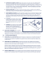
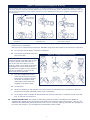
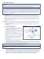
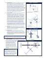
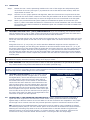
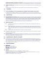
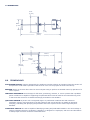
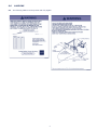
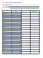
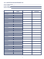
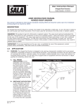
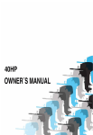
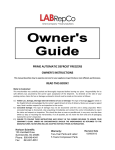
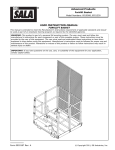
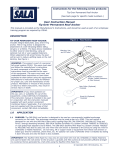
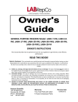
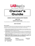
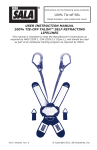
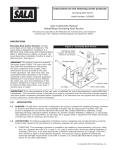
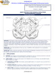
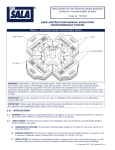
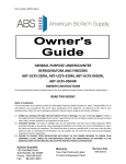
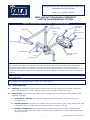
Instructions for the following series products:
Perimeter Limiter System
Model No. 2100090, 2100091
User Instruction Manual Perimeter
Limiter Counterweight System
Figure 1 - Assembled Perimeter Limiter Counterweight System
Mast:
7.5 ft or 9.5 ft.
(2.3 m or 2.9 m)
Mast Arm
Lifting
Shackles
Positioning
Handles
Rear
Foot Pad Jack
Weight Cart
Anchor Points
Positioning Bars
Additional Weights
(Optional)
Front
Foot Pad Jack
WARNING: This product is part of a fall arrest system. These instructions must be provided to all users
and rescuers (see section 8 Terminology) using this equipment. The user must read and understand these
instructions before using this equipment. The user must follow the manufacturer’s instructions for each
component of the system. Manufacturer’s instructions must be followed for proper use and maintenance of this
equipment. Alterations or misuse of this equipment, or failure to follow instructions, may result in serious injury
or death.
IMPORTANT: If you have questions on the use, care, or suitability of this equipment for your application,
contact DBI‑SALA.
IMPORTANT: Before using this equipment, record the product identification information from the ID label into
the inspection and maintenance log in section 10.0 of this manual.
1.0APPLICATION
1.1 PURPOSE: The Perimeter Limiter System is designed for use as an anchoring means for a personal fall
arrest system (PFAS) for a person working on form work, flat roofs or similar structures.
1.2 LIMITATIONS: The following limits apply to the installation and use of Perimeter Limiter System. Other
limitations may apply:
A. HORIZONTAL LIFELINE: The Perimeter Limiter System is not rated for use as an anchor for a
horizontal lifeline.
B. SYSTEM CAPACITY: The maximum capacity of the Perimeter Limiter System is two persons, each with
a maximum combined weight including tools and clothing, of 310 lbs. (141 kg).
C. surface Conditions: The Perimeter Limiter System must not be used under conditions where
the surface is coated with frost, snow, ice, standing water, grease or oil, or other lubricating or friction
reducing materials.
© Copyright 2007, DB Industries, Inc.
D. PERSONAL FALL ARREST SYSTEM: PFASs used with this roof anchor must meet applicable OSHA,
state, federal and ANSI requirements. PFASs incorporating a full body harness must be capable of
arresting a worker’s fall with a maximum arresting force of no greater than 900 lbs. (4 kN) and limit the
free fall distance to 6 ft. (1.8 m) or less. The deceleration distance for a PFAS must be 42 inches (1.1 m)
or less [47 inches (1.2 m) in Canada]. Reference ANSI Z359.1, OSHA and CSA Z259.11 requirements.
The system must be rigged in a way that limits free fall to 6 ft. or less. Contact DBI‑SALA if you have
questions or concerns regarding free fall limits.
e. Surface Structure: The surface on which the Perimeter Limiter is installed must be capable of
supporting the weight of the Perimeter Limiter and any additional loading as a result of fall arrest forces.
Do not install the system on an uneven surface or a slope of greater than 5°.
f. ENVIRONMENTAL HAZARDS: Use of this equipment in areas where environmental hazards exist may
require additional precautions be taken to reduce the possibility of injury to the user or damage to the
equipment. Hazards may include, but are not limited to: high heat, extreme cold, caustic chemicals,
corrosive environments, high voltage power lines, explosive or toxic gases, moving machinery, or
sharp edges. Contact DBI‑SALA if you have questions about using this equipment where environmental
hazards exist.
Figure 2 -System Location
g. Location: The Perimeter Limiter must be
located a sufficient distance from the edge of a
working surface. Minimum distance allowable
from the front of the unit is 2 ft. (.6 m) and
from the side of the unit is 3 ft. (.9 m) See
Figure 2.
2 ft Min.
H. TRAINING: This equipment must be installed
and used by persons who have been properly
trained in its correct application and use.
Installation and use of this equipment must be
supervised by a qualified person, as defined by
OSHA fall protection standards.
(.6 m Min.)
Front
Leading Edge
3 ft Min.
(.9 m Min)
Side Leading Edge
1.3 Applicable standards: Refer to national
Standards including ANSI Z359 (.0, .1, .2, .3,
and .4) family of standards on fall protection, ANSI A10.32, and applicable local, state and federal (OSHA)
requirements governing occupational safety for more information about work positioning systems. Refer to
CSA Z259.13 in Canada for more information on personal fall arrest systems and associated components.
2.0SYSTEM REQUIREMENTS
2.1 COMPATIBILITY OF COMPONENTS: DBI‑SALA equipment is designed for use with DBI‑SALA approved
components and subsystems only. Substitutions or replacements made with non-approved components
or subsystems may jeopardize compatibility of equipment and may effect the safety and reliability of the
complete system.
2.2 COMPATIBILITY OF CONNECTORS: Connectors are considered to be compatible with connecting
elements when they have been designed to work together in such a way that their sizes and shapes do
not cause their gate mechanisms to inadvertently open regardless of how they become oriented. Contact
DBI‑SALA if you have any questions about compatibility.
Connectors (hooks, carabiners, and D‑rings) must be capable of supporting at least 5,000 lbs. (22.2 kN).
Connectors must be compatible with the anchorage or other system components. Do not use equipment
that is not compatible. Non-compatible connectors may unintentionally disengage. See Figure 3. Connectors
must be compatible in size, shape, and strength. Self locking snap hooks and carabiners are required by
ANSI Z359.1 and OSHA and CSA Z259.12 in Canada.
2.3 MAKING CONNECTIONS: Only use self-locking snap hooks and carabiners with this equipment. Only use
connectors that are suitable to each application. Ensure all connections are compatible in size, shape and
strength. Do not use equipment that is not compatible. Ensure all connectors are fully closed and locked.
Figure 3 - Unintentional Disengagement (Roll-out)
If the connecting element that a snap hook (shown) or carabiner attaches to is undersized or irregular in shape, a situation
could occur where the connecting element applies a force to the gate of the snap hook or carabiner. This force may cause the
gate (of either a self-locking or a non-locking snap hook) to open, allowing the snap hook or carabiner to disengage from the
connecting point.
Small ring or
other
non-compatibly
shaped element
1. Force is applied to the
snap hook.
2. The gate presses against the
connecting ring.
3. The gate opens allowing the
snap hook to slip off.
DBI‑SALA connectors (snap hooks and carabiners) are designed to be used only as specified in each
product’s user’s instructions.
See Figure 4 for inappropriate connections. DBI‑SALA snap hooks and carabiners should not be connected:
A. To a D‑ring to which another connector is attached.
B. In a manner that would result in a
load on the gate.
Figure 4 - Inappropriate Connections
NOTE: Large throat snap hooks should
not be connected to standard size D‑rings
or similar objects which will result in a
load on the gate if the hook or D‑ring
twists or rotates. Large throat snap hooks
are designed for use on fixed structural
elements such as rebar or cross members
that are not shaped in a way that can
capture the gate of the hook.
C. In a false engagement, where
features that protrude from the
snap hook or carabiner catch on
the anchor and without visual
confirmation seems to be fully
engaged to the anchor point.
D. To each other.
E. Directly to webbing or rope lanyard or tie-back (unless the manufacturer’s instructions for both the
lanyard and connector specifically allows such a connection).
F. To any object which is shaped or dimensioned such that the snap hook or carabiner will not close and
lock, or that roll-out could occur.
2.4 Installation LOAD: The surface on which the Perimeter Limiter is installed must be capable of
supporting the weight of the unit and fall arrest loads. The maximum static load is 470 lbs. (213 kg), the
maximum foot pad loading during fall arrest for one user is 1,200 lbs. (545 kg) and 2000 lbs. (900 kg) for
two users. See section 7, for the weight of each Perimeter Limiter model.
3.0Assembly AND USE
WARNING: Do not alter or intentionally misuse this equipment. Consult with DBI‑SALA if using this equipment
in combination with components or subsystems other than those described in this manual. Some subsystems and
components combinations may interfere with the proper operation of this equipment. Use caution when using
this equipment around moving machinery, electrical and chemical hazards, and sharp edges.
WARNING: Working at height has inherent risks. Some risks are noted here but are not limited to the following:
falling, suspension/prolonged suspension, striking objects, and unconsciousness. In the event of a fall arrest and/
or subsequent rescue (emergency) situation, some personal medical conditions may affect your safety. Medical
conditions identified as risky for this type of activity include but are not limited to the following: heart disease,
high blood pressure, vertigo, epilepsy, drug or alcohol dependence, psychiatric illness, impaired limb function
and balance issues. We recommend that your employer/physician determine if you are fit to handle normal and
emergency use of this equipment.
3.1 BEFORE EACH USE inspect this equipment according to steps listed in section 5. Do not use this equipment
if inspection reveals an unsafe or defective condition. Plan your use of the fall protection system prior to
exposing workers to dangerous situations. Consider all factors affecting your safety before using this system.
Read and understand all manufacturer’s instructions for each component of the personal fall arrest system.
All DBI-SALA harnesses and connecting subsystems are supplied with separate user instructions. Keep all
instructions for future reference.
3.2 PLANyour fall arrest system before starting your work. Take into consideration factors affecting your safety at any
time during use. The following list gives some important points you must consider when planning your system:
A. Surface Structure: The surface structure must be capable of supporting the required loads. See
section 2.4.
Figure 5 - Safe Work Zone
B. OTHER CONSIDERATIONS:
• Always work within the safe work zone of the
Perimeter Limiter to avoid the possibility of rocking
or tipping the unit. See Figure 5.
• Personal fall arrest systems must be rigged to limit
any free fall to a maximum of 6 ft. (1.8 m) (OSHA
and ANSI Z359.1) (see section 1.2 F).
• Do not work above the surface of the Perimeter
Limiter level since an increased free fall distance will
result.
• Avoid working where your line may cross or tangle
with that of another worker or another object.
• Do not allow the lifeline to pass under arms or
between legs.
2 ft. Min
(.3 m Min)
Front
Leading Edge
26 ft. Max
(7.9 m Max)
Side
Leading Edge
24 ft. Max
(7.9 m Max)
Perimeter
Limiter Safe
Work Zone
• Never clamp, knot or otherwise prevent the lifeline
from retracting or being taut, avoid slack line.
• The Perimeter Limiter has two shackles designed for lifting the unit: one on the gusset at the base of the
mast and the other on the top center of the weight cart. See Figure 1. Use these shackles for lifting the
unit to the work area. Always use both shackles when lifting the unit.
Warning: Do not attach a personal fall arrest system to the lifting shackles. The shackles are not rated for fall
arrest and in the event of a fall, serious injury or death could occur.
Important: Do not lengthen the SRL lifeline by connecting a lanyard or similar component without consulting
DBI‑SALA.
C. TOTAL FALL DISTANCE: Should a fall occur, there must be sufficient clearance in the fall area to arrest
the fall before striking the ground or other object. The total fall distance is the distance measured from
the onset of a fall to the point where the fall is arrested. A number of factors can influence the total fall
distance including; user’s weight, anchorage location relative to the fall (swing fall), body support with
sliding D‑ring, and the type of fall arrest equipment you attach to the anchor. For specific clearance
requirements read and follow the manufacturers’s instructions for your fall arrest equipment.
D. SWING FALLS: See Figure 6. Swing falls occur when
the anchorage point is not directly above the point
where a fall occurs. The force of striking an object
while swinging (horizontal speed of the user due to the
pendulum affect) can be great and may cause serious
injury. Swing falls can be minimized by working as
close to the anchorage point as possible. In a swing fall
situation, the total vertical fall distance of the user will
be greater than if the user had fallen vertically directly
below the anchorage point. The user must therefore
account for an increase in the total free fall distance
and the area needed to safely arrest the fall.
E. SHARP EDGES: Avoid working where the connecting
subsystem (i.e. self retracting lifeline (SRL), full
body harness, lanyard, lifeline, etc.) or other system
components will be in contact with, or abrade against
unprotected sharp edges. See Figure 7. If working
with this equipment near sharp edges is unavoidable,
protection against cutting must be provided by using
a heavy pad or other means over the exposed sharp
edge. If you are not using the Leading Edge SRL (PN
3504500 or 3504600), it is recommended that an
energy absorber (PN 1220362) be installed in-line
between the harness and the self retracting lifeline
to further protect the worker. Compatibility and total
fall distance issues must be considered if this is done.
Contact DBI‑SALA before using in-line energy absorbing
components or lanyards with self retracting lifelines.
F. RESCUE: When using this equipment, the employer
must have a rescue plan and the means at hand to
implement it and must communicate that plan to users,
authorized persons, and rescuers.
G. AFTER A FALL: Any equipment which has been
subjected to the forces of arresting a fall or exhibits
damage consistent with the effect of fall arrest forces as
described in section 5, must be removed from service
immediately and destroyed by the user, the rescuer, or
an authorized person.
WARNING: Read and follow the manufacturer’s instructions
for associated equipment (i.e. SRL, full body harness, lanyard,
lifeline, etc.) used in your personal fall arrest system.
Figure 6 - Swing Falls
Unexpected Hazards
Swing Fall Hazard
Figure 7 - Sharp Edges
Leading
Edge SRL
Carabiner
Full Body
Harness
Padding
3.3 SYSTEM assembly: Figure 1 shows the Perimeter Limiter
Sharp Edge
Anchor assembled. The Perimeter Limiter is shipped with
the mast arm installed backwards
Figure 8 Unit Alignment
for space saving concerns. When
the anchor arrives, remove
the bolt that goes through the
mast and arm, remove the arm
and rotate it 180° to its proper
orientation and replace it. Then
replace the bolt through the arm
and mast and tighten the nut with
a wrench.
Warning: The Perimeter Limiter
Anchor system must only be used with
the arm extending in the direction
opposite the weight cart within 45°
(see Figure 8). Any other orientation
will diminish the effectiveness to the
counterweight system and use could
result in severe injury or death.
45°
45°
3.4 Operation
Step 1. Position the Unit: Use the positioning handles on the rear of the weight cart and positioning bars
on the front of the unit (see Figure 1) to position the unit at the desired work location, within the
requirements of section 3.2.
Step 2. Once the unit is in proper position and alignment, Raise the front and rear tire jacks until the foot
pads reach the work surface. Continue to rotate the jack handles until all three wheels are lifted off
the work surface and rotate freely to ensure the weight of the unit is transferred to the foot pads.
Step 3. Attach your personal fall arrest system (PFAS) to the attachments points on the mast arm (see
Figure 1). Refer to the PFAS manufacturer’s instructions for correct attachment and use of the PFAS.
Do not attach more than one PFAS to an attachment point. Do not attach more that two PFAS to the
Perimeter Limiter.
Warning: Do not move the Perimeter Limiter while a user is attached to it.
3.5 Optional Mast for 9.5 ft. (2.9 m) configuration: If you are retrofitting your Perimeter Limiter
with the optional 9.5 ft. (2.9 m) mast, remove the mast arm as previously indicated. After the mast arm is
removed, remove the bolt at the base of the mast and lift the mast off the base.
Replace the old mast with the new one and replace the original bolt and nut, then place the mast arm on top
of the new mast and replace its bolt and nut. Be sure to tighten both nuts with a wrench to make sure they
are snug.
Along with the 9.5 ft (2.9 m) mast, you need to install an additional weight set into the weight box. To
install the extra weights, Use the lifting point shackles to raise the Perimeter Limiter about 1 ft. (.3 m) off
the ground. Place two of the weights inside the weight box and center them over one of the mounting holes
in the permanent weights. Slide one of the supplied long, 1-in. bolts into the hole from the bottom of the
cart and apply the washer and nut to the end of the bolt after it has passed through the two extra weights.
Snug the nut down with a wrench. Repeat this procedure with the other two extra weights over the second
mounting hole.
Warning: Do not use the 9.5 ft. mast without installing the additional weights. In the event of a fall without
the additional weights, the anchor could tip causing sever injury or death.
3.6 BODY SUPPORT: A full body harness must be worn for fall arrest applications. For general fall protection
use, connect to the D‑ring on the back between the shoulders (dorsal D‑ring).
IMPORTANT: Body belts are not allowed for free fall situations. Body belts increase the risk of injury during fall
arrest in comparison to a full body harness. Limited suspension time and the potential for improperly wearing a
body belt may result in added danger to the user’s health.
3.7 Optional Digital Winch: If you purchase a Digital
Winch, a mounting bracket is shipped with it. To mount
the Digital Winch, remove the detent pin from the winch
mounting bracket, place the slot on the lower edge of
the bracket onto the pin on the bracket on the Perimeter
Limiter mast and then rotate the winch toward the mast
until the upper holes in the two brackets align. Insert the
detent pin through the holes in both brackets. Make sure
the detent pin goes all the way through both brackets and
clicks into place. See Figure 9. Route the winch’s wire rope
over the roller at the top of the mast and over the pulley at
the center of the mast arm. Refer to the Digital Winch user
instruction for proper use and inspection.
Figure 9 - Digital Winch
Detent Pin
3.8 CONNECTING TO THE Perimeter Limiter ANCHOR: Figure 7 illustrates the proper connection of
typical fall arrest equipment to the Perimeter Limiter anchor. Always protect the lifeline from abrading
against sharp or abrasive surfaces on the roof. Make sure all the connections are compatible in size, shape
and strength. Never connect more than two personal protective system to a Perimeter Limiter at a time.
SRL: Connection to the installed Perimeter Limiter anchor may be made by using a carabiner to attach a
self retracting lifeline (SRL) to one of the anchor points on the mast arm of the Perimeter Limiter and then
attaching the self locking snap hook at the end of the SRL lifeline to the back dorsal D‑ring (fall arrest
attachment point) of the user’s body support (i.e. full body harness). When connecting, make sure the
connections are fully closed and locked. Review section 3.2 if using an SRL near sharp edges.
ENERGY ABSORBING LANYARDS OR LIFELINE: Connect the energy absorbing end of the lanyard to the
back D‑ring on the full body harness (see section 3.6). See manufacturer’s instruction for more information.
3.9 NORMAL OPERATION: Once attached, the worker is free to move about within the recommended working
areas.
If a fall has been arrested, the system must be taken out of service and inspected, see section 5.0.
4.0TRAINING
4.1 It is the responsibility of all users of this equipment to understand these instructions, and are trained
in the correct installation, use, and maintenance of this equipment. These individuals must be aware of
the consequences of improper installation or use of this equipment. This user manual is not a substitute for a
comprehensive training program. Training must be provided on a periodic basis to ensure proficiency of the users.
5.0
INSPECTION
5.1 BEFORE EACH INSTALLATION: Inspect the Perimeter Limiter components, and other system components
according to these or other manufacturer’s instructions. System components must be formally inspected by
a qualified person (other than the user) at least annually. Formal inspections should concentrate on visible
signs of deterioration or damage to the system components. Items found to be defective must be replaced.
Do not use components if inspection reveals an unsafe or defective condition. Record results of each
inspection in the inspection and maintenance log in section 10.0 of this manual.
5.2 INSPECTION STEPS:
Step 1. If additional weights have been installed, make sure the bolts and nuts holding them in place are
snug and secure.
Step 2. Inspect the Perimeter Limiter Anchor for physical damage. Look carefully for any signs of cracks,
dents or deformities in the metal. Do not use an anchor that has been subjected to fall arrest forces
unless it has been inspected by a competent person and permission to use it has been expressed in
writing.
Step 3. Inspect the Perimeter Limiter Anchor for signs of excessive corrosion.
5.3 If inspection reveals an unsafe or defective condition, remove the unit from service and destroy, or contact
DBI‑SALA for possible repair.
5.4 USER EQUIPMENT: Inspect each system component or subsystem (i.e. SRL, full body harness, lanyard,
lifeline, etc.) per associated manufacturer’s instructions. Refer to manufacturer’s instruction supplied with
each system component for inspection procedures.
6.0
MAINTENANCE, SERVICE, STORAGE
6.1 The Perimeter Limiter System components require no scheduled maintenance other than periodic greasing
of the weight box pin bushing and the shaft for the swivel wheel at the front of the unit and repair or replacement of
items found defective during inspection. See section 5.0. If components become heavily soiled with grease,
paint, or other substances, clean with appropriate cleaning solutions. Do not use caustic chemicals that
could damage system components.
7.0SPECIFICATIONS
7.1 MATERIALS:
Mast: powder-coated steel
Mast Arm: powder-coated steel
Base Arm: powder-coated steel
Weight Box: galvanized steel
7.2 Weight:
Model No. 2100090 (7.5 ft. [2.3 m] configuration): 1655 lbs. (751 kg)
Kit Model No. 2100091 (9.5 ft [2.9 m] configuration): 1855 lbs. (841 kg) (includes 200 lbs. [91 kg] of
additional weight and mast for 9.5 ft. [2.9 m] configuration).
Additional Counterweight: 50 lbs. (23 kg) each.
7.3 Dimensions:
74 in.
(1.9 m)
48 in.
(1.2 m)
4 in.
(.1 m)
188.5 in.
(4.8 m)
4 in.
(.1 m)
74.9 in.
(2.5 m)
75.7 in.
(1.9 m)
89.2 in.
(2.26 m)
99.8 in.
(.1 m)
4 in.
(.1 m)
4 in.
(.1 m)
8.0
Terminology
Authorized Person: A person assigned by the employer to perform duties at a location where the person will
be exposed to a fall hazard (otherwise referred to as “user” for the purpose of these instructions).
Rescuer: Person or persons other than the rescue subject acting to perform an assisted rescue by operation of a
rescue system.
Certified Anchorage: An anchorage for fall arrest, positioning, restraint, or rescue systems that a qualified
person certifies to be capable of supporting the potential fall forces that could be encountered during a fall
or that meet the criteria for a certified anchorage prescribed in this standard.
Qualified Person: A person with a recognized degree or professional certificate and with extensive
knowledge, training, and experience in the fall protection and rescue field who is capable of designing,
analyzing, evaluating and specifying fall protection and rescue systems to the extent required by this
standard.
Competent Person: One who is capable of identifying existing and predictable hazards in the surroundings or
working conditions which are unsanitary, hazardous, or dangerous to employees, and who has authorization
to take prompt corrective measures to eliminate them.
9.0LABELING
9.1 The following labels must be present and fully legible:
2100090
10.0inspection and maintenance log
Date of manufacture model number date of purchase Inspection date
inspection items noted
corrective action
Approved by:
Approved by:
Approved by:
Approved by:
Approved by:
Approved by:
Approved by:
Approved by:
Approved by:
Approved by:
Approved by:
Approved by:
Approved by:
Approved by:
Approved by:
Approved by:
Approved by:
Approved by:
Approved by:
10
maintenance performed
10.0inspection and maintenance log
Date of manufacture model number date of purchase Inspection date
inspection items noted
corrective action
Approved by:
Approved by:
Approved by:
Approved by:
Approved by:
Approved by:
Approved by:
Approved by:
Approved by:
Approved by:
Approved by:
Approved by:
Approved by:
Approved by:
Approved by:
Approved by:
Approved by:
Approved by:
Approved by:
11
maintenance performed
A Capital Safety Company
USA 3833 SALA Way
Red Wing, MN 55066-5005
Toll Free: 800-328-6146
Phone: (651) 388-8282
Fax: (651) 388-5065
Email: [email protected]
www.capitalsafety.com
Canada
260 Export Boulevard
Mississauga, Ontario L5S 1Y9
Toll Free: 800-387-7484
Phone: (905) 795-9333
Fax: (905) 795-8777
Email: [email protected]
www.capitalsafety.com
This manual is available for download at www.capitalsafety.com.
I S O
9001
Certificate No. FM 39709
12
Form: 5902381
Rev: A