1
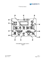
TT1200
Turbine Temperature Test Set
USER INSTRUCTION MANUAL
BARFIELD M/N TT1200
56-101-00920
Revision D
November 7, 2014
__________________________________
BARFIELD, INC.
Corporate Headquarters
4101 Northwest 29th Street
Miami, Florida 33142
www.barfieldinc.com
Email: [email protected]
Copyright © 2014 Barfield Inc. All Rights Reserved.
TT1200 User Manual
CONTACT INFORMATION
Users are requested to notify the manufacturer of any discrepancy, omission, or error
found in this manual. Inquiries should include specific questions and reference the
publication title, number, chapter, page, figure, paragraph, and effective date.
Please send comments to:
TECHNICAL CUSTOMER SUPPORT - GSTE
BARFIELD, INC.
P.O. BOX 025367
MIAMI, FL 33102-5367
USA
56-101-00920-D
Nov / 7 / 14
Telephone
(305) 894-5400
(800) 321-1039
Fax
(305) 894-5401
Email
[email protected]
Contact
Page ii
TT1200 User Manual
ATTENTION
Although every effort has been made to provide the end user of this equipment with the
most current and accurate information, it may be necessary to revise this manual in the
future. Please be sure to complete and return the enclosed OWNER WARRANTY
REGISTRATION CARD to Barfield in order to validate the warranty and to ensure that
you will receive updated information when published. You MUST have your name and
address on file at Barfield as a registered user of this equipment, to be able to obtain
the service covered by the warranty.
Visit the company website, http://barfieldinc.com/, for publication updates.
Please send the Registration Card to:
Barfield, Inc.
P.O. Box 025367
Miami, FL 33102-5367
USA
56-101-00920-D
Nov / 7 / 14
Attention
Page iii
TT1200 User Manual
REVISION RECORD
REV.
ECO #
REV. DATE
A
N/A
Jan. 24, 1995
Initial Release
B
---
Oct. 20, 2000
Added Addendum A (Option A). Revised Table of
Contents accordingly.
C
260-00729
Sep. 15, 2008
Updated Company Logo and Format
D
260-01059
Nov. 7, 2014
Updated Barfield logo
56-101-00920-D
Nov / 7 / 14
DESCRIPTION OF CHANGE
REV
Page iv
TT1200 User Manual
MAINTENANCE AND REPAIR INFORMATION
The manufacturer of this equipment does not recommend the user to attempt any
maintenance or repair. In case of malfunction, contact the manufacturer, to obtain the
list of approved repair facilities worldwide, ensuring that this equipment will be serviced
using proper procedures and certified instruments.
BARFIELD PRODUCT SUPPORT
DIVISION
Telephone
(305) 894-5400
(800) 321-1039
Fax
(305) 894-5401
Shipping Address:
Barfield, Inc.
4101 NW 29th Street
Miami, Florida 33142
USA
Mailing Address:
Barfield, Inc.
P.O. Box 025367
Miami, FL 33102-5367
USA
56-101-00920-D
Nov / 7 / 14
Maint.
Page v
TT1200 User Manual
This page intentionally left blank.
56-101-00920-D
Nov / 7 / 14
Blank
Page vi
TT1200 User Manual
TABLE OF CONTENTS
Contact Information
Attention Page
Revision Record
Maintenance and Repair Information
Table of Contents
PAGE
CHAPTER 1: GENERAL INFORMATION
1. Purpose of Manual ............................................................................................................... 1
2. General Description of the Test Set..................................................................................... 1
3. Switching Functions ............................................................................................................. 2
4. Recertification ....................................................................................................................... 4
CHAPTER 2: OPERATION
1. General Operating Instructions ............................................................................................ 5
2. System Lead Resistance Measurement ............................................................................. 6
3. Thermocouple Resistance Test Procedure ......................................................................... 7
4. Insulation Testing Procedure ............................................................................................... 8
5. Indicator Test Procedure (With Specified Lead Resistance) .............................................. 8
6. Potentiometric or Servoed Indicator Test Procedure (Without Lead Resistance).............. 9
7. Temperature Measurement Test Procedure ...................................................................... 11
CHAPTER 3: SPECIFICATIONS AND CAPABILITIES
1. Physical Data ...................................................................................................................... 12
2. Specifications ...................................................................................................................... 12
3. Capabilities .......................................................................................................................... 13
CHAPTER 4: RECEIVING, SHIPPING, AND STORAGE
1. Receiving ............................................................................................................................. 14
2. Shipping............................................................................................................................... 14
3. Storage ................................................................................................................................ 14
56-101-00920-D
Nov / 7 / 14
TOC
Page vii
TT1200 User Manual
This page intentionally left blank.
56-101-00920-D
Nov / 7 / 14
Blank
Page viii
TT1200 User Manual
CHAPTER 1: GENERAL INFORMATION
1. PURPOSE OF MANUAL
A.
This publication contains the description and the operating procedures for the:
TT1200 DIGITAL TURBINE TEMPERATURE TEST SET, P/N 101-00920 Fig. 1.
Manufactured by:
BARFIELD, INC.
4101 NW 29th Street
Miami Florida 33142
USA
B.
This manual is developed to address the above Test Set especially designed to test and
calibrate Chromel-Alumel (CH-AL) temperature indicating systems. It contains complete
instructions for maintenance inspection, testing, troubleshooting, and calibration of systems
installed on aircraft engines.
2. GENERAL DESCRIPTION OF THE TEST SET
The TT1200 provides the means for quickly troubleshooting aircraft temperature indicating
systems. It has sufficient sensitivity and accuracy to test thermocouple and system resistance,
insulation, and indicator calibration. It features portability, simplicity of operation, direct reading,
and multi-function versatility.
A.
TT1200 Features
(1)
Specifically designed to meet all requirements for testing aircraft Chromel-Alumel
(CH-AL) temperature measuring systems and provides an accurate display of
thermocouple outputs in degrees Celsius (°C).
(2)
Thermocouple and lead resistance measurements to 0.001 ohm and insulation
measurements up to 200 megohms.
(3)
Simulates thermocouple outputs and system lead resistances from 2 to 25 ohms.
(4)
Completely self-contained, self-monitoring, easily portable temperature and
resistance measuring and simulating device for all CH-AL systems with the capability
to bench test indicators.
56-101-00920-D
Nov / 7 / 14
CH. 1
Page 1 of 14
TT1200 User Manual
(5)
Human engineered for maximum ease of operation and maintenance with state of
the art low battery drain circuitry with automatic ambient test point temperature
correction.
(6)
A large, 9mm (0.35") high characters, 4 1/2 digit Liquid Crystal Display (LCD) with
pre-programmed legends.
(7)
Carrying Case features;
(a) Fabricated from high impact plastic.
(b) Provides a pouch on the rear for test lead storage.
(c) The lid contains a placard of abridged operating instructions for the experienced
technician.
NOTE:
For nonexperienced personnel it is advisable to become familiar with
this publication, the TT1200, and the aircraft system before performing
any test or checks.
3. SWITCHING FUNCTIONS (Ref. Fig. 1)
A.
The ON/OFF toggle switch (1) applies power for all functions.
B.
The RANGE switch (2), a 4 position rotary switch, permits selection of the resistance and
insulation ranges, 20Ω, 200Ω 2KΩ and 20KΩ for RES MEAS or 200KΩ, 2MΩ, 20MΩ and
200MΩ for INS MEAS. The fourth position is also used for 0 ohm system resistance for the
IND TEST function.
C.
The PTM (Press To Measure) pushbutton (3), when depressed activates the TT1200
excitation and measuring circuitry when the FUNCTION switch is set to the RES MEAS or
INS MEAS positions.
D.
The PTS (Press To Set) pushbutton (4), when depressed with test leads shorted and the
FUNCTION switch in the RES MEAS position connects the SYS RES potentiometer for
system resistance adjustment.
E.
The SYStem RESistance control knob (5), a 10 turn potentiometer used to adjust system
lead resistance, 2 to 25 ohms, when test leads are shorted and the PTS pushbutton is
depressed.
F.
The TEST connector (6) provides the means for connecting the TT1200's standard leads
or specifically designed interface cabling.
56-101-00920-D
Nov / 7 / 14
CH. 1
Page 2 of 14
TT1200 User Manual
a Sabena technics company
TT1200 FRONT PANEL LAYOUT
Figure 1
56-101-00920-D
Nov / 7 / 14
CH. 1
Page 3 of 14
TT1200 User Manual
G.
The display (7) is a 4 1/2 digit LCD which provides all the readings with associated units
and legends for low battery warning (BAT) and an open thermocouple circuit (OPEN).
H.
Two battery holders (8) house 4 each AA alkaline cells which provide power for all test set
functions.
I.
The TEMP ADJ control knob (9), a 10 turn potentiometer permits coarse adjustment of the
temperature or millivoltage while the FINE control (10), provides exact adjustment of the
readings which are displayed on the LCD when the FUNCTION switch is in the IND TEST
position.
J.
The oC/MV toggle switch (11) allows the user to configure the test set to display either oC
or millivoltage when the FUNCTION switch is set to IND TEST or TEMP MEAS positions.
The center position, MV (amb_ient comp_ensated), provides the operator with a
millivoltage display that is based on a reference junction at 0oC. The lower position, MV,
may be thought of as a DVM function and provides the user with a display equivalent to
having a DVM connected in parallel at the test set's Red and Black clips.
K.
The FUNCTION switch (12), a 4 position rotary switch that permits selection of the four
principal test functions, RESistance MEASure, INSulation MEASure, INDicator TEST and
TEMPerature MEASure.
L. The 1oC/.1oC toggle switch (13) allows the user to set the test set's display resolution when
the FUNCTION switch is set to IND TEST or TEMP MEAS and oC is selected.
4. RECERTIFICATION
The Test Set P/N 101-00920 has a one-year recertification requirement. Maintenance
required by this unit must be performed by qualified technicians in a shop equipped with the
necessary tooling and facilities.
56-101-00920-D
Nov / 7 / 14
CH. 1
Page 4 of 14
TT1200 User Manual
CHAPTER 2: OPERATION
1. GENERAL OPERATING INSTRUCTIONS
Consult temperature indicator system and/or engine manufacturer's instructions for procedures
and specifications. Read complete TT1200 Operation procedures before attempting to use the
TT1200.
A.
Protective Circuits;
(1)
B.
Although the TT1200 has input protection the test set should never be connected to
an energized circuit.
Preparation For Use:
(1)
Battery Installation / Replacement;
(a) Using a coin or screwdriver remove the covers from the battery holders located
in the upper right corner of the panel. Invert the TT1200 so that batteries slide
out. With the TT1200 upright insert two AA alkaline batteries into each holder
with the negative terminals down for all.
(b) To check the 4 AA batteries set the FUNCTION switch to RES MEAS, the
RANGE switch to 20 ohm position and short test lead clips together.
(c) Depress the PTM pushbutton switch. If BAT is displayed replace the batteries as
detailed above.
C.
Precautions
(1)
Do NOT press either pushbutton with test clips connected to the aircraft indicator.
The current applied may damage the indicator.
(2)
Do NOT connect test clips to an energized circuit. Although the TT1200 is provided
with protective devices, not all damaging potentials can be made completely safe.
(3)
Allow sufficient time for test clips to stabilize to the temperature of the terminals to
which they are connected for temperature tests.
(4)
Measure system and thermocouple resistance with a cold engine for greatest
accuracy.
56-101-00920-D
Nov / 7 / 14
CH. 2
Page 5 of 14
TT1200 User Manual
D.
(5)
To conserve battery power, place ON/OFF switch to OFF when the test set is not in
use.
(6)
BAT warning displayed indicates about 10% battery life of the batteries remain and
they should be replaced.
Hot Engine Testing
A hot engine will cause thermocouples to generate a small potential which will produce
errors in measured resistance values. This effect is inherent in any type resistance
measuring instrument.
The effect can be circumvented by taking two measurements; the first with test leads
connected in one polarity, and then reversing the lead connections for the second
measurement. The true value is equal to the average of the two readings (i.e., add the
two readings and divide by two). The two readings must be taken in quick succession
so that the thermocouple temperature will be the same for both readings. If the
thermocouples are too hot, the readings will be too far from nominal to provide sufficient
accuracy. In such a case, wait for the engine to cool further.
2. SYSTEM LEAD RESISTANCE TEST PROCEDURE
A.
Disconnect thermocouple leads from system temperature indicator.
B.
Carefully connect test lead clips to each of the lead wires insuring a good electrical
connection.
C.
Set the FUNCTION switch to RES MEAS.
D.
Set the RANGE switch to 200 ohm.
E.
Setting of 1oC/.1oC switch is immaterial.
F.
Setting of oC/MV switch is immaterial.
G.
Place ON/OFF switch to ON and depress the PTM pushbutton switch.
H.
Display will indicate resistance in ohms to within ± 0.01 ohm.
If a 1__.__ is displayed, resistance is greater than 199.99 ohms or there is an open
circuit.
56-101-00920-D
Nov / 7 / 14
CH. 2
Page 6 of 14
TT1200 User Manual
I.
Interchange RED and BLACK test clip connections and the display should repeat when the
PTM pushbutton is depressed. If the reading does not repeat, the engine thermocouples
may be hot. (Ref. Para. 1. D. above.)
NOTE: Resistance must be within manufacturer's specifications. If results are slightly
outside limits, repeat entire procedure to insure test failure is not due to human
error.
J.
Place ON/OFF switch to OFF, disconnect the TT1200 and return aircraft to original
configuration.
3. THERMOCOUPLE RESISTANCE TEST PROCEDURE
A.
Disconnect thermocouple leads from system temperature indicator.
B.
Carefully connect test lead clips to each of the lead wires insuring a good electrical
connection.
C.
Set the FUNCTION switch to RES MEAS.
D.
Set the RANGE switch to 200 ohm.
E.
Setting of 1oC/.1oC switch is immaterial.
F.
Setting of oC/MV switch is immaterial.
G.
Place ON/OFF switch to ON and depress the PTM pushbutton switch.
H.
Display will indicate resistance in ohms to within ± 0.01 ohm.
If a 1__.__ is displayed, resistance is greater than 199.99 ohms or there is an open
circuit.
I.
Interchange RED and BLACK test clip connections and the display should repeat when the
PTM pushbutton is depressed. If the reading does not repeat, the engine thermocouples
may be hot. (Ref. Para. 1. D. above.)
NOTE: Resistance must be within manufacturer's specifications. If results are slightly
outside limits, repeat entire procedure to insure test failure is not due to human
error.
J.
Place ON/OFF switch to OFF, disconnect the TT1200 and return aircraft to original
configuration.
56-101-00920-D
Nov / 7 / 14
CH. 2
Page 7 of 14
TT1200 User Manual
4. INSULATION TESTING PROCEDURE
A.
Disconnect one or both leads at system temperature indicator. Then connect the BLACK
lead clip to ground and the RED lead clip to one or both thermocouple system lead wires.
(Ref. engine manufacturers' Maintenance Manual for specific hookup.)
B.
Set the FUNCTION switch to INS MEAS.
C.
Set the RANGE switch to 2M ohm or as desired.
D.
Setting of 1oC/.1oC switch is immaterial.
E.
Setting of oC/MV switch is immaterial.
F.
Place ON/OFF switch to ON and depress the PTM pushbutton switch.
G.
Display will indicate insulation resistance in 1,000,000's of ohms (megohms).
If a 1.____ is displayed, resistance is greater than 1.999 megohms or there is an open
circuit.
NOTE: Resistance to ground must not be less than manufacturer's specifications.
H.
Place ON/OFF switch to OFF, disconnect the TT1200 and return aircraft to original
configuration.
5. INDICATOR TEST PROCEDURE (With Specified Lead Resistance)
A.
Set the FUNCTION switch to RES MEAS.
B.
Set the RANGE switch to 200 ohm.
C.
Place ON/OFF switch to ON.
D.
Short test lead clips together and depress the PTS pushbutton while adjusting SYS RES
control knob for displayed system resistance to be simulated.
E.
Set the FUNCTION switch to IND TEST.
F.
Set 1oC/.1oC switch as desired.
G.
Set oC/MV switch to oC or as desired.
H.
Disconnect aircraft thermocouple leads from temperature indicator.
56-101-00920-D
Nov / 7 / 14
CH. 2
Page 8 of 14
TT1200 User Manual
I.
Connect test lead clips to indicator terminals, OBSERVING POLARITY. Alumel is negative
(-) and connects to the TT1200 BLACK clip: Chromel is positive (+) and connects to the
TT1200 RED clip.
J.
Set TEMP ADJ control for the desired test temperature as displayed on the digital
indicator. It may be necessary to use the FINE control to achieve the exact settings.
K.
Compare readings of indicator under test with TT1200 indications.
NOTE: Indicator
specifications.
L.
must
agree
with
TT1200
reading
to
within
manufacturers'
Place ON/OFF switch to OFF, disconnect the TT1200 and return aircraft to original
configuration.
6. POTENTIOMETRIC OR SERVOED TYPE INDICATOR TEST PROCEDURE (Without
Lead Resistance)
A.
B.
General
(1)
The Potentiometric or Servoed indicator, as it is generally referred to may be
recognized by its multiple pin electrical connector and the requirement of aircraft
electrical power to operate.
(2)
Thermocouple lead resistance is not critical with this type of indicator, and usually
need not be measured.
System Lead Resistance Measurement:
(1)
Disconnect aircraft power to indicator. (Ref. Maintenance Manual)
(2)
Disconnect electrical connector at rear of indicator.
(3)
Connect TT1200 leads to probe pins sized to fit chromel and alumel pin sockets of
aircraft plug removed from indicator.
(4)
Follow Para. 2. System Lead Resistance Test Procedure, steps C. through H above.
NOTE: Lead resistance is not critical, generally in the order of 5 to 100 ohms.
(Ref. Maintenance Manual for specific values.)
56-101-00920-D
Nov / 7 / 14
CH. 2
Page 9 of 14
TT1200 User Manual
C.
D.
E.
Thermocouple Resistance Measurement:
(1)
Disconnect aircraft power to indicator. (Ref. Maintenance Manual)
(2)
Follow Para. 3. Thermocouple Resistance Test Procedure above.
Insulation Testing:
(1)
Disconnect aircraft power to indicator. (Ref. Maintenance Manual)
(2)
Disconnect electrical connector at rear of indicator
(3)
Follow Para. 4. Insulation Testing Procedure, steps B. thru F. above, using probe
pins at aircraft plug or make connection at engine thermocouple terminal blocks.
Indicator Test:
(1)
Disconnect aircraft power to indicator. (Ref. Maintenance Manual)
(2)
Disconnect leads from indicator at engine thermocouple terminal block.
(3)
Set the FUNCTION switch to IND TEST.
(4)
Set the RANGE switch to 20 K ohm - 0 Ω SYS RES.
(5)
Set 1oC/.1oC switch as desired.
(6)
Set oC/MV switch to oC or as desired.
(7)
Connect test lead clips to indicator leads OBSERVING POLARITY. Alumel is
negative (-) and connects to the TT1200 BLACK clip: Chromel is positive (+) and
connects to the TT1200 RED clip.
(8)
Place aircraft temperature indicating system power to ON.
(9)
Place ON/OFF switch to ON.
(10) Rotate the TEMP ADJ control for desired test points as read on the TT1200 digital
display.It may be necessary to use the FINE control to achieve the exact settings.
(11) Compare readings of indicator under test with TT1200 indications.
NOTE: Indicator must agree with TT1200 reading to within manufacturer's
specifications.
56-101-00920-D
Nov / 7 / 14
CH. 2
Page 10 of 14
TT1200 User Manual
(12) Place aircraft temperature indicating system power to OFF.
(13) Place ON/OFF switch to OFF, disconnect the TT1200 and return aircraft to original
configuration.
7. TEMPERATURE MEASUREMENT TEST PROCEDURE
A.
Set the FUNCTION switch to TEMP MEAS.
B.
Set the RANGE switch to 20 K ohm - 0 Ω SYS RES.
C.
Set 1oC/.1oC switch as desired.
D.
Set oC/MV switch to oC or as desired.
CAUTION: AIRCRAFT INDICATORS OF THE D'ARSONVAL TYPE MUST NOT BE
CONNECTED DURING THIS TEST. D'ARSONVAL INDICATORS MAY
GENERALLY BE RECOGNIZED BY THE ABSENCE OF A MULTI-PIN
CONNECTOR AND WILL USUALLY HAVE TWO TERMINAL POSTS OR
TERMINAL SCREWS.
E.
Connect test lead clips to thermocouple leads OBSERVING POLARITY. Alumel is
negative (-) and connects to the TT1200 BLACK clip: Chromel is positive (+) and connects
to the TT1200 RED clip.
F.
Display will indicate thermocouple temperature directly in oC.
NOTE: If the word OPEN is displayed, there is an open circuit in the thermocouple or
lead wires.
56-101-00920-D
Nov / 7 / 14
CH. 2
Page 11 of 14
TT1200 User Manual
CHAPTER 3: SPECIFICATIONS AND CAPABILITIES
1. PHYSICAL DATA
A.
Height: 6.5 in (16.5 cm)
B.
Width: 9.3 in (23.6 cm)
C.
Depth : 7.0 in (17.8 cm)
D.
Weight: 5.4 lbs (2.4 kg)
2. SPECIFICATIONS
A.
B.
Temperature Measurement:
(1)
Type: K (CH-AL Thermocouple).
(2)
Range: 0 to 1200oC certified, -50 to +1250oC extended.
(3)
Accuracy: Typical measurement error at 25oC ambient: less than ±0.3oC.
Lead Resistance:
(1)
Range; 0 -19.999 ohms in 0.001 ohm increments.
Range; 0 -199.99 ohms in 0.01 ohm increments.
Range; 0 -1.9999 K ohms in 0.1 ohm increments.
Range; 0 -19.999 K ohms in 1 ohm increments.
(2)
C.
Accuracy; ± 0.05% of reading ± 2 counts
Insulation:
(1)
Range; 0 -199.9 kΩ in 0.1K ohm increments.
Range; 0 -1.999 MΩ in 1K ohm increments.
Range; 0 -19.99 MΩ in 10K ohm increments.
Range; 0 -199.9 MΩ in 100K ohm increments.
(2)
Accuracy; ± 5% of reading ± 2 counts.
(3)
Excitation; 45V DC nominal.
56-101-00920-D
Nov / 7 / 14
CH. 3
Page 12 of 14
TT1200 User Manual
D.
Simulated System Resistance:
(1)
Adjustment Range; Less than 2.0 ohms to greater than 25 ohms.
(2)
Fixed Setting; Less than 0.1 ohm.
3. CAPABILITIES
A.
Measures and displays resistance of thermocouples, thermocouple rings and system lead
circuits.
B.
Measures and displays insulation resistance of system wiring and other components.
C.
Simulates CH-AL thermocouples with or without simulated system lead resistance.
D.
Measures and displays values of CH-AL thermocouples in terms of degrees Celsius (oC)
temperature.
E.
Automatically compensates for ambient temperature at test lead connection junction point
or indicates this cold junction temperature.
56-101-00920-D
Nov / 7 / 14
CH. 3
Page 13 of 14
TT1200 User Manual
CHAPTER 4: RECEIVING, SHIPPING, AND STORAGE
1. RECEIVING
No special unpacking procedures are necessary. It is recommended that factory shipping
container and packing materials be retained should it become necessary, for any reason, to
reship the Test Set.
It is also recommended that the Test Set be carefully inspected for damage. If damaged,
immediately notify both the carrier and manufacturer.
2. SHIPPING
Use standard delicate electronic equipment packaging procedures when packing the Test Set
for reshipment.
3. STORAGE
Store in a cool dry place.
56-101-00920-D
Nov / 7 / 14
CH. 4
Page 14 of 14