1
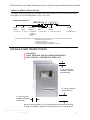
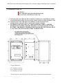
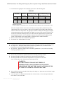
SENS EnerGenius Fire Pump and Emergency Power System Charger Installation and User Manual Installation & Operation Manual NRG Series Battery Chargers for NFPA-20 Centrifugal Fire Pump And NFPA-110 Emergency Power System Installations ® ™ SENS Part Number: Document Revision: DCN Number: Date: 101301 N 106194 October 25, 2012 Installation or service questions? Call SENS at 1.800.742.2326 (303.678.7500) between 8 a.m. and 5 p.m. (Mountain Time) Monday through1.800.742.2326 Friday, or visit our website. Service hotline: 1.303.678.7500 Copyright © Stored Energy Systems LLC 2006 1840 Industrial Circle Longmont, CO 80501 Phone: 303.678.7500 800.742.2326 Fax: 303.678.7504 Email: [email protected] Web: www.sens-usa.com 1 SENS EnerGenius Fire Pump and Emergency Power System Charger Installation and User Manual IMPORTANT SAFETY INSTRUCTIONS FOR INSTALLER AND OPERATOR 1. 2. 3. 4. 5. 6. SAVE THESE INSTRUCTIONS. DO NOT EXPOSE CHARGER TO RAIN OR SNOW. Use of an attachment not recommended or sold by SENS may result in a risk of fire, electric shock, or injury to persons. ONLY TRAINED AND QUALIFIED PERSONNEL MAY INSTALL AND SERVICE THIS UNIT. Do not operate charger if it has received a sharp blow, been dropped, or otherwise damaged in any way; shut off power at the branch circuit protectors and have the unit serviced or replaced by qualified personnel. To reduce risk of electric shock, disconnect the branch circuit feeding the charger before attempting any maintenance or cleaning. Turning off controls will not reduce this risk. WARNING: RISK OF EXPLOSIVE GASES. A. WORKING IN THE VICINITY OF A STORAGE BATTERY IS DANGEROUS. STORAGE BATTERIES GENERATE EXPLOSIVE GASES DURING NORMAL BATTERY OPERATION. FOR THIS REASON, IT IS OF UTMOST IMPORTANCE THAT EACH TIME BEFORE USING YOUR CHARGER, YOU READ THIS MANUAL AND FOLLOW THE INSTRUCTIONS EXACTLY. B. To reduce the risk battery explosion, follow these instructions and those published by the battery manufacturer and the manufacturer of any equipment you intend to use in the vicinity of a battery. Review cautionary markings on these products and on the engine. 7. PERSONAL PRECAUTIONS A. Someone should be within range of your voice or close enough to come to your aid when you work near a storage battery. B. Have plenty of fresh water and soap nearby in case battery electrolyte contacts skin, clothing, or eyes. C. Wear complete eye protection and clothing protection. Avoid touching eyes while working near a storage battery. D. If battery electrolyte contacts skin or clothing, wash immediately with soap and water. If electrolyte enters eye, immediately flood the eye with running cold water for at least 10 minutes and get medical attention immediately. E. NEVER smoke or allow a spark or flame in vicinity of battery or engine. F. Be extra cautious to reduce risk of dropping a metal tool onto battery. It might spark or short circuit battery or other electrical part that may cause explosion. Using insulated tools reduces this risk, but will not eliminate it. G. Remove personal metal items such as rings, bracelets, necklaces, and watches when working with a storage battery. A storage battery can produce a short circuit current high enough to weld a ring or the like to metal, causing a severe burn. H. Use this charger for charging LIQUID ELECTOLYTE LEAD-ACID batteries only. Do not use this battery charger for charging dry cells, alkaline, lithium, nickel-metal-hydride, or nickel-cadmium batteries. These batteries may burst and cause injuries to persons and damage to property. I. NEVER charge a frozen battery. Service hotline: 1.800.742.2326 1.303.678.7500 2 SENS EnerGenius Fire Pump and Emergency Power System Charger Installation and User Manual MODEL NUMBER CONFIGURATION This manual contains important safety, installation and operating instructions for SENS battery charger model NRG-22-10 (field configurable for 12V or 24V, 10A). Model Number Breakout NRG 22-10Output Voltage 22: 12/24 volts Output Current Input Voltage - Frequency 10: 10 Amps 1 Alarm System Code H: 120/208-240V, 1: combined alarm 50/60HZ** R: 120/208-240V, 60Hz* Agency Approval Category LP: Listed-fire pump service E: OSHPD labeled*** NOTE: All Fire Pump/Emergency Power System models have Alarm System Code 1 and remote battery temperature sensing. Contact the factory for confirmation. *UL listed, CSA certified **UL listed, CSA certified and CE marked ***California Special Seismic Certification Pre-Approval INSTALLATION INSTRUCTIONS WARNING: ONLY TRAINED AND QUALIFIED PERSONNEL MAY INSTALL AND SERVICE THIS UNIT. 6” (15 cm) minimum ventilation clearance top and bottom 12” (30 cm) minimum above floor level 2” (5 cm) minimum ventilation clearance on each side Mount to vertical surface of 3/4” (19 mm) plywood or other material of equal strength and durability, using four mounting screws of 1/4” (6 mm) diameter. Service hotline: 1.800.742.2326 1.303.678.7500 3 SENS EnerGenius Fire Pump and Emergency Power System Charger Installation and User Manual 1. PREPARING FOR USE: WARNING: ONLY TRAINED AND QUALIFIED PERSONNEL MAY INSTALL AND SERVICE THIS UNIT. A. INSTALLATION OF THE UNIT MUST COMPLY WITH LOCAL ELECTRICAL CODES AND OTHER APPLICABLE INSTALLATION CODES (SUCH AS NFPA 20 OR NFPA 110). B. INSTALLATION MUST BE MADE ACCORDING TO THE INSTALLATION INSTRUCTIONS AND ALL APPLICABLE SAFETY REGULATIONS. C. IN ORDER TO RETURN 100% OF A DISCHARGED BATTERY’S AMPEREHOUR RATING WITHIN 24 HOURS WITHOUT CAUSING DAMAGE TO THE BATTERY, THE REMOTE TEMPERATURE SENSOR MUST BE INSTALLED AT A LOCATION THAT TRACKS BATTERY TEMPERATURE. Charger Dimensions: W: 7.66 Inches (195 mm) H: 12.50 Inches (318 mm) D: 6.48 Inches (165 mm) This drawing shows the enclosed model. The open-frame version has identical dimensions. Service hotline: 1.800.742.2326 1.303.678.7500 4 SENS EnerGenius Fire Pump and Emergency Power System Charger Installation and User Manual Neutral 115/230VAC Grounding Conductor Temperature Sensor Alarm Contacts -Battery +Battery Use wire routing devices to hold alarm and temperature sensor conductors at least 1/4” (6.3mm) away from power conductors. Use power conductors rated 90C or higher. Input conductors must be suitable for 10A circuits. Battery conductors must be suitable for 30A circuits. See Section 5. Alarm and temperature sensor may use low power (Class 2) conductors. C. This unit is permanently connected to the AC circuit and to the battery. An external disconnect device with a minimum of 0.12”(3 mm) pole separation must be located in the AC input to the charger. Do not energize the AC supply circuit until ALL wiring is connected, internal controls are properly set, and the cover is secured. Always shut the AC supply circuit off before installing or removing any wiring or opening the cover for any reason. Always observe proper polarity of the DC output leads. Always connect the output leads in this order: ungrounded charger output first, then ungrounded battery terminal, then grounded charger output, and grounded battery terminal last. If the battery must be disconnected for service, remove the output wiring in the reverse of the order given above. Service hotline: 1.800.742.2326 1.303.678.7500 5 SENS EnerGenius Fire Pump and Emergency Power System Charger Installation and User Manual D. Be sure battery terminals are clean and properly tightened. Be careful to keep corrosion from coming in contact with eyes. E. Add distilled water to each cell until the electrolyte reaches the level specified by the battery manufacturer. This helps purge excess gas from the cells. Do not over fill. For a battery without cell caps, carefully follow the manufacturer’s recharging instructions. F. Study all battery manufacturer’s specific precautions such as removing or not removing cell caps while charging and recommended rates of charge. The recommended charge current range must include the rated output current of this charger, which is 10 amperes. Set the float voltage jumper to the battery manufacturer’s recommended float charge voltage. Incorrect charge voltage will accelerate generation of explosive gases, increasing the risk of fire or explosion. G. Enable the automatic boost charge mode (equalizing charge) only if recommended by the battery manufacturer H. Determine the voltage of the battery by referring to the engine or battery owner’s manual and make sure that the 12V/24V select jumper is set to the correct voltage. 2. CHARGER LOCATION Do not set a battery or any other object on top of the charger. This will obstruct the ventilation openings and cause excessive heating. Ensure the charger is protected from blowing or dripping water. 3. GROUNDING INSTRUCTIONS This battery charger should be connected to a grounded, metal, permanent wiring system; or an equipment grounding conductor (earthing conductor) should be run with the circuit conductors and connected to the equipment grounding terminal in the charger. This terminal is marked with the ground symbol. Connections to the battery charger should comply with all local codes and ordinances. 4. NEUTRAL CONNECTION The grounded circuit conductor (neutral) should be connected to the terminal marked “N” on the input terminal block, TB1. 5. WIRE RATINGS A. All conductors should be rated for use at 90º C or higher. B. All input and output conductor sizes should be coordinated with the fault protection devices: 10A on AC input (14 AWG, 2.5 mm2 typical), 30A on DC output (10 AWG, 6.0 mm2 typical). 1 A on Alarm terminal block (20 AWG, 0.5 mm2 typical). C. Before installation, ensure adequate battery to charger wire gauge. Wire gauge that is too small may activate the open battery detector and the charger will shut down. The maximum allowed resistance seen by the charger is found in TABLE 1. These figures already include an allowance for charger variations (they are 80% of the typical trip-point) and are for the complete circuit: total of battery leads, battery's internal resistance, and any external equipment. The total resistance seen by the charger must not exceed the following values: TABLE 1 Maximum Resistance Service hotline: 1.800.742.2326 1.303.678.7500 12V 24V 58m 116 6 SENS EnerGenius Fire Pump and Emergency Power System Charger Installation and User Manual D. To determine the appropriate cable and length, please refer to the following table: TABLE 2 Wire Size AWG mm2 Resistance per Foot mΩ/Ft. 10 8 6 6.0 10 16 1.00 0.63 0.40 Maximum Charger to Recommended Charger to Battery Distance (Ft.) Battery Distance (Ft.) 12V 24V 12V 24V 25 40 63 50 79 126 10 15 24 19 30 48 The above lengths consider the resistance of the battery and cables only and do not take into account any additional interconnects. The above lengths are for operation at 25C. For high temperature installations (40C) reduce lengths by 10%. In the case of high resistance in the cables to the battery the charger Battery Fault LED may flash (approximately once every 60 seconds). Cable runs exceeding the proper length for the cable gauge used most often cause this problem. The appropriate solution is to change the cable gauge to properly correspond with the necessary cable length (see TABLE 2). In some cases where the resistance is not too far above maximum, the charger may recover after some time (approximately 10 minutes) and start charging the batteries. If it is not possible to decrease the system resistance the Battery Fault feature can be disabled. Please contact SENS at 1-800-742-2326 for further information. E. Refer to local electrical code for additional requirements. F. See Section 9 for Terminal Block wire ranges. 6. FUSE RATINGS A. CAUTION: For continued protection against risk of fire, replace only with same type and rating of fuse. B. DC Output Fuse – SENS part number 304530. Bussman Type BK/ATC-30, or Littelfuse 257030 [ATO30], 30A, 32V, fast acting, blade type automotive C. AC Input Fuse – SENS part number 304473. Bussman Type BK/AGC-10, 10A, 250VAC, fast acting, ferrule type cylindrical, ¼” X 1-¼” 7. MOUNTING LOCATION A. See the safety instructions for important information concerning the charger location. B. The charger should be installed in a sheltered area, protected from rain and snow. C. The charger should not be located where temperatures are expected to be colder than -20º C, or hotter than +40º C for operation at rated output current. WARNING: NEVER CHARGE STORAGE BATTERIES AT TEMPERATURES ABOVE OR BELOW THE LIMITS SPECIFIED BY THE BATTERY MANUFACTURER. NEVER ATTEMPT TO CHARGE A FROZEN BATTERY. D. Allow sufficient room for routing the fixed wiring to the charger. AC input enters the left side; DC output and alarms exit on the right. E. Leave clear space for ventilation all around the unit: at least 6 inches (15 cm) at the top and bottom; at least 2 inches (5 cm) on the sides. Service hotline: 1.800.742.2326 1.303.678.7500 7 SENS EnerGenius Fire Pump and Emergency Power System Charger Installation and User Manual F. Charger should be mounted on a flat vertical surface so that the chassis does not warp when tightened to the wall. G. The charger should be mounted vertically, with the input and output terminal blocks lowermost WARNING: OTHER MOUNTING ORIENTATIONS INTERFERE WITH PROPER VENTILATION AND MAY CAUSE THE CHARGER TO OVERHEAT. H. Do not mount the charger over any heat generating equipment. I. Minimize vibrations that the charger will be subjected to. 8. STATIC DISCHARGE PRECAUTIONS The printed circuit board contains static sensitive components. Damage can occur even when static levels are too low to produce a noticeable discharge shock. To avoid static discharge damage: A. Handle the charger by the chassis only. Remove the cover only when access is essential for installation and service, and replace it promptly when finished. B. If possible, wear an approved static protection strap. If one is not available, touch one hand to the chassis before contacting any other part of the charger. 9. MOUNTING PROCEDURES WARNING: THIS CHARGER IS INTENDED FOR COMMERCIAL AND INDUSTRIAL USE. ONLY TRAINED PERSONNEL WHO ARE QUALIFIED TO PERFORM ELECTRICAL INSTALLATIONS SHOULD INSTALL OR SERVICE THIS UNIT. The charger mounts to a wall or other vertical support. The mounting surface must safely support the charger’s weight, which is 25 pounds (11.3 kg), and also the weight of the fixed wiring. Mounting on a concrete surface: All mounting hardware is provided by the installer. Use optional ¾ inch thick, 18 in. x 24 in. sheet of marine plywood (not provided) to provide a suitable mounting surface for the charger. Drill four holes to secure the plywood to the wall using a minimum of four ¼ in. drive pin type expansion anchors to secure the plywood to the wall. Secure the plywood to the wall. Drill four holes using the mounting diagram on pg. 4 for ¼ in. (or M6) draw nut type expansion anchors through the plywood into the cement wall. Insert the four draw nut type expansion anchors through the plywood into the cement wall. Mount charger to draw nut type expansion anchors with nuts and flat washers. Service hotline: 1.800.742.2326 1.303.678.7500 8 SENS EnerGenius Fire Pump and Emergency Power System Charger Installation and User Manual Mounting on a drywall: Use ¾ in. thick plywood to span two vertical support members in the wall. The plywood sheet normally does not have to be more that 2 ft. by 2 ft. square. Place plywood to avoid electrical wiring, plumbing, etc., concealed behind wall. Secure the plywood to the vertical support members using ¼ in. by 2 inch lag bolts and flat washers in a minimum of four places. Mark four holes on the plywood using the mounting diagram on pg. 4. Drill pilot holes into the plywood to secure the mounting bolts. Mount charger using four 1/4 inch by 1/2 in. or M6 lag bolts and flat washers Mounting on a metal surface: Mount charger using four ¼ -20 by 3/4 in. hex head bolts, flat washers and split lock washers or M6 hardware to attach the battery charger to a frame, panel or cross member in four places. Use the mounting diagram on pg. 4 to place the pilot holes, if needed. Tighten all bolts to recommended torque of 45-50 inch pounds. 10. WIRING A. All wiring must comply with applicable codes and local ordinances. See Section 5 for recommended gauges. B. The charger contains a DC output fuse for internal fault protection, but this will not protect the DC wiring from fault currents available from the battery. CONSULT NATIONAL CODES AND LOCAL ORDINANCES TO DETERMINE IF ADDITIONAL BATTERY FAULT PROTECTION IS NECESSARY IN YOUR INSTALLATION WARNING: ENSURE THAT AC POWER IS DISCONNECTED AT THE CIRCUIT BREAKER OR OTHER SAFETY DISCONNECT BEFORE WIRING THE CHARGER. C. Connect the equipment grounding conductor (earthing) to the charger’s grounding terminal. This should always be the first wire connected and the last wire disconnected. D. Connect the DC output conductors to TB3. Make the connections in the order shown in Figure 2A (negative ground) or Figure 2B (positive ground). The terminals accept 10 through 6 AWG conductors. CAUTION: OBSERVE POLARITY. THE POSITIVE CHARGER OUTPUT TERMINAL IS LABELED “+” AND THE NEGATIVE TERMINAL IS LABELED “-”. WARNING: BE SURE TO ROUTE DC POWER WIRING AT LEAST ¼ INCH (6.3 MM) AWAY FROM AC WIRING, ALARM WIRING, AND THE CIRCUIT BOARD. Service hotline: 1.800.742.2326 1.303.678.7500 9 SENS EnerGenius Fire Pump and Emergency Power System Charger Installation and User Manual FIGURE 2A FIGURE 2B E. Connect the AC line and neutral conductors at TB1. If there is an identified grounded circuit conductor (neutral), attach it to the terminal marked N. TB1 will accept 14-6 AWG (2.5-16 mm2) conductors. WARNING: BE SURE TO ROUTE ALL AC WIRING AT LEAST ¼ INCH (6 mm) AWAY FROM DC WIRING, ALARM WIRING, AND THE CIRCUIT BOARD. F. Connect the alarm wiring to their respective terminals on TB5. Route alarm wiring through the plastic bushing below TB5, keeping the conductors at least ¼ inch (6 mm) away from DC wiring, AC wiring, and the circuit board. The terminals accept 24-16 AWG (0.25-1.5 mm2) conductors. WARNING: CONNECT ALARM TERMINALS ONLY TO LOW VOLTAGE, LIMITED ENERGY (“CLASS 2”) CIRCUITS. ALARM CIRCUITS ARE RATED 2A AT 30 VDC, 0.5A AT 125 VAC, MAXIMUM SWITCHING CAPACITY 62.5VA, 60W. RELAY CONTACTS Common OPEN ON ALARM CLOSE ON ALARM Not Used MASTER ALARM Not Used Not Used Not Used TB5-1 No Connection TB5-2 No Connection TB5-3 No Connection TB5-4 COM TB5-5 OK TB5-6 FAIL Defaults to Fail with no AC input TB5-7 No Connection TB5-8 No Connection TB5-9 No Connection TB5-10 No Connection TB5-11 No Connection TB5-12 No Connection TB5-13 No Connection TB5-14 No Connection TB5-15 No Connection G. Temperature sensor: Battery temperature increases at the high charging rate required to meet NFPA-20 and NFPA-110 recharge time requirements. To return into a fully discharged battery 100% of the battery’s ampere-hour rating within 24 hours without causing damage to the battery, attach the temperature sensor to a surface that accurately tracks the battery temperature, such as to the positive battery terminal, or against the outside of the battery case. This unit is shipped with a temperature sensor attached to terminal block TB4. The sensor is not polarized, so it does not matter which lead connects to terminal #1. Service hotline: 1.800.742.2326 1.303.678.7500 10 SENS EnerGenius Fire Pump and Emergency Power System Charger Installation and User Manual The temperature sensor leads are low voltage, limited energy (“Class 2”) circuits. Route the wires through the plastic bushing below TB5, keeping the conductors at least ¼ inch (6 mm) away from DC wiring, AC wiring, and the circuit board. The terminals will accept 20 through 16 AWG conductors. H. Verify that all connections are secure and in the proper locations. Tighten all unused screws on the terminal blocks to secure them against vibration. I. Ensure all wires are routed so the cover will not pinch them. 11. INTERNAL ADJUSTMENTS WARNING: MAKE SURE THE AC POWER TO THE CHARGER IS SHUT OFF WHILE MAKING THE FOLLOWING ADJUSTMENTS. AC line voltage switch 110-120V: Use 115V position 208-240V: Use 230V position Meter Display Jumper JP800. Choose VOLTS, AMPS, or AUTO for meter display view. “Jump start” battery initialization mode Jumper JP1. Configure battery and output voltage settings. Automatic boost jumper Use HIGH setting for fire pump and emergency power applications Float voltage jumper Set according to battery supplier’s specifications Battery range jumper (12V or 24V battery) A. Set the AC voltage select switch (SW100) according to the line voltage. Use the 115V position for nominal mains voltages between 110V and 120V. Use the 230V position for nominal mains voltages between 208V and 240V. B. Set the battery range jumper (JP1A) according to nominal battery voltage. Use the 12V position for 12V batteries. Use the 24V position for 24V batteries. C. For NFPA-20 fire pump and NFPA-110 emergency power system applications, set the boost mode jumper (JP1B) to the HIGH setting. WARNING: THE HIGH BOOST SETTING IS FOR USE ONLY IN NFPA-20 FIRE PUMP OR NFPA-110 EMERGENCY POWER SYSTEM INSTALLATIONS. THIS SETTING INCREASES BATTERY WATER CONSUMPTION. REGULAR MAINTENANCE OF BATTERY ELECTROLYTE LEVELS IS ESSENTIAL. THIS SETTING IS COMPATIBLE ONLY WITH VENTED LEAD-ACID BATTERIES OF 6 OR 12 CELLS, 1.2551.290 SPECIFIC GRAVITY, AND UP TO 220 AMPERE-HOUR CAPACITY. DO NOT USE THIS SETTING WITH NICKEL-CADMIUM, VALVE-REGULATED LEAD ACID, OR ANY TYPE OF “MAINTENANCE-FREE” BATTERY. Service hotline: 1.800.742.2326 1.303.678.7500 11 SENS EnerGenius Fire Pump and Emergency Power System Charger Installation and User Manual D. Set the float voltage select jumper (JP1C) according to the battery manufacturer’s recommended 25ºC float voltage. The settings are: 13.62/27.24 for 6 or 12 cell lead-acid at 2.27V/cell 13.50/27.00 for 6 or 12 cell lead-acid at 2.25V/cell 13.31/26.62 for 6 or 12 cell lead-acid at 2.22V/cell 13.08/26.16 for 6 or 12 cell lead-acid at 2.18V/cell 14.30/28.60 and 12.87/25.74 are not used for fire pump and emergency power system applications. E. Set the Display Selector jumper to one of the 3 available positions on JP800 (see photograph previous page): VOLTS – Place the short jumper in the “upper” position next to the word “VOLTS”. The 3-digit LED meter display will show DC Volts only AUTO – Place the short jumper in the center position next to the word “AUTO”. The 3-digit LED meter display will automatically and continuously alternate between DC Amps and DC Volts. The display shows DC Amps for approximately 6 seconds and DC Volts for approximately 3 seconds. AMPS – Place the short jumper in the “lower” position next to the word “AMPS”. The 3-digit LED meter display will show DC Amps only. WARNING: USE ONE JUMPER ONLY ON THE DISPLAY SELECTOR JP800. USE ONLY THE “SHORT” JUMPER PROVIDED FOR JP800, TO AVOID INTERFERENCE WHEN REPLACING THE COVER (“TALL” JUMPERS ARE TO BE USED ONLY ON JP1). F. The JUMP position allows initial charging of Nickel Cadmium batteries, or new lead acid batteries supplied from the manufacturer dry and discharged, from a zero charge state. The JUMP feature can also be used when recharging excessively discharged batteries already in service. To initially charge/commission zero charge batteries, place a jumper (spare provided with charger) in the JUMP position on JP1. Operate the charger long enough to retain more than 1.5V/cell for lead acid and 1.0V/cell for nickel cadmium batteries or until the charger returns to FLOAT MODE (FLOAT MODE LED will be green). See SENS Application Note 10 to finish fully commissioning the batteries, as using the JUMP feature alone is not sufficient. Once the batteries are fully charged, the jumper may be removed or left in the JUMP position permanently. The jumper may remain in the JUMP position permanently to ensure that the charger is able to recharge very low or dead batteries. If battery voltage is below 9V (12V system) or 18V (24V system) when AC power is restored and the JUMP feature is not activated, the charger will go into Battery Fault (alarm state that disables charger). In this situation the charger will not charge the batteries. If the JUMP feature is enabled when AC power is restored, the charger will begin charging. Depending on the battery state of charge, the charger may go into Battery Fault and remain so for some period of time (generally 12 – 24 hours) while the batteries are slowly charged. The Battery Fault LED will cycle (approximately once every minute) during this time. Once Battery Fault stops cycling, the charger will return to FLOAT or BOOST MODE as normally demanded. WARNING: USE THE JUMP FEATURE ONLY WITH LIQUID ELECTROLYTE NICKELCADMIUM BATTERIES, OR WITH RECENTLY FILLED NEW LEAD ACID BATTERIES SUPPLIED FROM THE MANUFACTURER DRY AND DISCHARGED. WHILE THE JUMP FEATURE MAY BE USED TO CHARGE EXCESSIVELY DISCHARGED LEAD ACID BATTERIES THAT HAVE ALREADY BEEN IN SERVICE, CONSULT THE BATTERY MANUFACTURER TO DETERMINE IF AND HOW THEY CAN SAFELY BE RESTORED TO SERVICE. WARNING: LEAVING A JUMPER IN THE JUMP POSITION DISABLES THE BATTERY VOLTAGE INTERLOCK, WHICH INCREASES THE RISK OF ACCIDENTALLY OVERCHARGING 12V BATTERIES WITH 24V SETTINGS. INCORRECT CHARGE VOLTAGE WILL ACCELERATE GENERATION OF EXPLOSIVE GASES, INCREASING THE RISK OF FIRE OR EXPLOSION. G. For fully enclosed models, replace the cover by sliding it straight onto the charger. Ensure the cover’s locating tabs engage the slots in the chassis. Secure the cover with its four mounting screws. Service hotline: 1.800.742.2326 1.303.678.7500 12 SENS EnerGenius Fire Pump and Emergency Power System Charger Installation and User Manual 12. CHECK OUT Green for temperature-corrected charger voltage Green for normal AC input Red for internal charger failure *Red for excessive battery voltage DC Volt/Amp Meter Display *Red for low battery voltage Red for low or missing AC input Green for normal voltage (float charge) Yellow for boost voltage (fast charge) Red for open, wrong voltage, reversed battery, or defective battery * Not currently used - see page 3 for model number breakdown See OPERATOR INSTRUCTION section for LED indicator definitions: A. Verify the status LEDs: AC FAIL should be ON. If not, the DC output may be open or reversed, or the battery may be extremely discharged. BATT FAULT should be OFF. If it lights, check for reversed polarity of the DC wiring. All other LEDs and the meter display should be off. B. Apply AC power by closing the branch circuit breaker and any other disconnect devices. C. The meter display should light immediately after power on. The green AC/ ON LED should light after a few seconds. The green T-COMP (Temperature Compensation) LED must be lighted, showing that the temperature compensator is operational. CAUTION: WITHOUT TEMPERATURE COMPENSATION, RECHARGE TIME MAY NOT COMPLY TO NFPA-20 AND NFPA-110 E. If the BATT FAULT LED lights when AC is applied, this indicates that the battery voltage does not agree with the Range jumper setting. The charger is interlocked, and will not operate in this condition. Disconnect AC power, then correct the jumper setting or battery voltage before proceeding. F. After a short delay (typically 10 seconds or less), the charger will produce output. Service hotline: 1.800.742.2326 1.303.678.7500 13 SENS EnerGenius Fire Pump and Emergency Power System Charger Installation and User Manual G. If the meter display jumper is selected to read Amps or automatic Volts/Amps: Current should be close to 10A if the battery requires recharging. When the BOOST MODE LED is lighted, the battery will be charged until it reaches the fast charge voltage (15.2/30.4V). When the battery is fully charged, the green FLOAT MODE LED will light and the charger output drops to the charge maintenance (float voltage) setting. Output current will be low if the battery is fully charged, possibly too low to read on the meter. This is normal, provided the correct charging voltage is present. The green FLOAT MODE LED should light when output current is below approximately 5 A. Wiring Diagram Service hotline: 1.800.742.2326 1.303.678.7500 14 SENS EnerGenius Fire Pump and Emergency Power System Charger Installation and User Manual OPERATOR INSTRUCTIONS WARNING: NO OPERATOR SERVICEABLE PARTS INSIDE. DO NOT OPEN. COVER MUST BE IN PLACE DURING USE. USE THIS CHARGER FOR CHARGING LEAD-ACID OR NICKEL-CADMIUM BATTERIES ONLY. A. ADVANCED DESIGN FEATURES Battery Friendly: Float and boost voltage selectable at install per specific battery vendor recommendations. Remote temperature compensation for most accurate float and boost voltage control. Able to charge a dead battery. Float and Boost voltage electronically controlled with a 4-rate fast charge program. See chart below. 4 -R A T E C H A R G IN G C h a rg e r in “fa st ch a rg e (b o o st) m o d e ” B oo st voltag e lim it C h a rg e r in “flo a t m o d e ” Vb O n ce bo os t volta ge is a ch ieved cu rre nt ta p ers o ff Current limit T ran sition : ch arge r shifts to flo a t m o d e w h e n b a tte ry c urren t a cc ep tan ce drop s C s H ig ar ge ch ar ng ch g ni ai ta ge nt te ar ai h ra ch in r r pe sh ur ge ni tc ar M on n ta en h tc ge B a tte ry cu rre n t a c c e p ta n c e Fi Battery voltage F loa t voltage lim it Temperature Compensation: The battery charger is temperature compensated to match the negative temperature coefficient of the battery. Thus, the output voltage will increase slightly as the temperature decreases and decrease as temperature increases. The output voltage is clamped at 0 and +40 Degrees C to protect against extremely high or low output voltage. See chart below. AUTOMATIC TEMPERATURE COMPENSATION Temperature vs. volts per cell lead acid Float volts per cell 2.7 2.6 SENS limits here to prevent damaging high voltages at customer equipment 2.5 SB AGM Gel NRG 2.4 2.3 2.2 2.1 2 -30 0 20 40 60 Temperature Degrees C 80 Fault Tolerant: The charger is protected from the following faults: Internal power component failures. Over heating (over temperature output power reduction). Protected against power line transients and surges. Battery Fault Protection and Alarm: The battery charger automatically checks the battery voltage before power-on startup. If the battery voltService hotline: 1.800.742.2326 1.303.678.7500 15 SENS EnerGenius Fire Pump and Emergency Power System Charger Installation and User Manual age is either too high or too low, the charger enters a “lockout” period for approximately 10 seconds before attempting an automatic restart. The “JUMP” feature (described in Section 11-F in this manual) may be used to allow the battery charger to override the lockout and start charging a low-voltage discharged battery. The battery charger will not start if the battery or battery cables have a short circuit, and will start automatically with a good battery if the short circuit is removed. In addition to detecting low battery voltage and short circuits, the battery charger also monitors the peak voltage at its DC output terminals and will enter lockout if the DC cable resistance is too high or if the battery’s internal resistance is too high. If a battery is connected backwards, this reverse polarity condition will keep the battery charger in lockout and it will remain in lockout until the battery is disconnected. A reverse polarity condition will not blow a fuse; the battery charger will start and run normally when a good battery is connected with correct polarity. Whenever one of these fault conditions triggers the battery fault protection circuitry as described above, the “Batt Fault” relay and LED are both activated. If polarity is correct, DC cables OK, and the “JUMP” feature attempted, the battery fault alarm most likely indicates a defective battery. Replace with a new battery. Robust Hardened Construction: Shock and Vibration tested to UL 991, 2G. Shock and Vibration tested to UL 991, 5G option available. Lightning transient immunity to ANSI/IEEE C62.41 Cat. B and EN 50082-2 heavy industrial. Wide operating temperature range: -20 to + 40 Degrees C. Charger will operate at reduced output current rating up to +60 Degrees C. Conformal coated printed wiring boards for erosion protection. W o r l d w i d e A g e n c y A p p r o v a ls : UL listed, UL 1012, UL 1236. CUL listed to CSA C22.2 107.2- M89. CE marked for EMC directive (industrial environment) and EN 60335-2-29. Worldwide operating voltage and frequency ranges. B. FRONT PANEL LED INDICATOR DEFINITIONS AND TROUBLE SHOOTING: Green for temperature-corrected charger voltage Green for normal AC input Red for internal charger failure *Red for excessive battery voltage DC Volt/Amp Meter Display *Red for low battery voltage Red for low or missing AC input Green for normal voltage (float charge) Yellow for boost voltage (fast charge) Red for open, wrong voltage, reversed battery, or defective battery * Not currently used - see page 3 for model number breakdown Service hotline: 1.800.742.2326 1.303.678.7500 16 SENS EnerGenius Fire Pump and Emergency Power System Charger Installation and User Manual ITEM TEXT LED 1 CHGR FAIL RED Meaning Charger Fail Troubleshooting Charger unable to provide charging current to battery or run-away charger output. Replace unit. AC input voltage is too low to supply proper current when load is applied. 2 AC FAIL RED 3 T-COMP GREEN 4 AC/ ON GREEN 5 FLOAT MODE GREEN Input AC Missing On if Temperature Compensation Working, Off if Temperature Compensation Option not used. Charger operating normally. Charger Output in Float Mode Control board is damaged and should be replaced. Check AC input voltage to charger. Have qualified installer check AC line voltage switch setting. Setting must agree with AC voltage at site. Check AC fuse. Confirm if temperature compensation is intended to be used. Only one sensor (Local or remote) should be connected. Should be on in normal use. If LED is OFF, AC FAIL or CHGR FAIL or BATT FAULT LED should be ON. If the automatic boost jumper is in the OFF location, this LED will always be on. If the automatic boost jumper is in the “NORM” location, this LED will come on after the battery is nearly charged up and will stay on. 6 BOOST MODE AMBER Charger Output in Boost Mode This LED will not be on if the automatic boost jumper is in the OFF location, or if the automatic boost jumper is in the “NORM” location and the battery is nearly fully charged up. 7 BATT FAULT RED Battery Fault-Charger automatically disabled: Battery reversed. High resistance in charger leads (leads too small, too long , poorly connected, open). See Section 5 for information on wire length and gauge. Battery internal open circuit. Battery voltage does not match charger voltage range Service hotline: 1.800.742.2326 1.303.678.7500 17 SENS EnerGenius Fire Pump and Emergency Power System Charger Installation and User Manual TROUBLESHOOTING GUIDE—REPEATED BLOWN AC FUSE START: AC FAIL LED red INPUT SWITCH CONFIGURED FOR 115V BUT SOURCE IS 230V? Y PROPERLY CONFIGURE SELECTION SWITCH N CORRECT AC INPUT SUPPLY PROBLEM END FUSE STILL BLOWS? N END Y Y AC FREQUENCY LOW? N Y N AC VOLTS CORRECT (MEASURE WITH MULTIMETER)? FUSE STILL BLOWS? Y N CORRECT AC INPUT SUPPLY PROBLEM FUSE STILL BLOWS? N END Y CONTACT CUSTOMER SERVICE Service hotline: 1.800.742.2326 1.303.678.7500 18 SENS EnerGenius Fire Pump and Emergency Power System Charger Installation and User Manual TROUBLESHOOTING GUIDE—AC FAIL ALARM START: AC FAIL LED red INPUT SELECTION SWITCH PROPERLY CONFIGURED? N ALARM STILL PRESENT? PROPERLY CONFIGURE SELECTION SWITCH N ALARM STILL PRESENT? CORRECT AC INPUT SUPPLY PROBLEM Y ALARM STILL PRESENT? REPLACE AC INPUT FUSE END N END Y N ALL CONNECTORS FIRMLY SEATED? N Y Y AC INPUT FUSE BLOWN? END Y Y AC VOLTS AND FREQ CORRECT (MEASURE WITH MULTIMETER)? N N ALARM STILL PRESENT? FIX CONNECTIONS END Y Y REPLACE CIRCUIT BOARD TRAY N ALARM STILL PRESENT? N END Y CONTACT CUSTOMER SERVICE Service hotline: 1.800.742.2326 1.303.678.7500 19 SENS EnerGenius Fire Pump and Emergency Power System Charger Installation and User Manual TROUBLESHOOTING GUIDE—CHARGER FAIL ALARM START: CHGR FAIL LED red AC VOLTS LOW (MEASURE WITH MULTIMETER)? Y ALARM STILL PRESENT? CORRECT AC INPUT SUPPLY PROBLEM END Y N ALL CONNECTORS FIRMLY SEATED? N N ALARM STILL PRESENT? FIX CONNECTIONS END Y Y REPLACE CIRCUIT BOARD TRAY N ALARM STILL PRESENT? N END Y CONTACT CUSTOMER SERVICE Service hotline: 1.800.742.2326 1.303.678.7500 20 SENS EnerGenius Fire Pump and Emergency Power System Charger Installation and User Manual TROUBLESHOOTING GUIDE—BATTERY FAULT ALARM START: BATT FAULT LED red BATT FAULT LED SOLID RED (NOT FLASHING)? HIGH RESISTANCE IN CHARGER OUTPUT LEADS? N Y Y FIX LEADS THAT ARE TOO LONG, TOO SMALL, POORLY CONNECTED OR OPEN (SEE MANUAL FOR WIRE LENGTH/GAUGE REQUIREMENTS) ALARM STILL PRESENT? N END Y N TO “BATTERY DEFECTIVE” BATTERY RANGE VOLTAGE JUMPER PROPERLY SET? ALARM STILL PRESENT? ADJUST JUMPER FOR 12V OR 24V BATTERY N N REPLACE CIRCUIT BOARD TRAY END Y Y ALARM STILL PRESENT? Y BATTERY REVERSE POLARIZED? Y ALARM STILL PRESENT? CORRECT BATTERY CONNECTION END CONTACT CUSTOMER SERVICE Y N FROM NO “HIGH RESISTANCE” N BATTERY DEFECTIVE (INTERNAL OPEN CIRCUIT, SHORT, ETC.)? Y REPLACE BATTERY N Service hotline: 1.800.742.2326 1.303.678.7500 N END Y N DC OUTPUT FUSE BLOWN? ALARM STILL PRESENT? Y REPLACE DC OUTPUT FUSE ALARM STILL PRESENT? N END Y 21 N END SENS EnerGenius Fire Pump and Emergency Power System Charger Installation and User Manual NORMAL SET UP: 1. Apply AC power by closing the branch circuit breaker and any other disconnect devices. 2. The meter display should light immediately after power on. The green AC/ ON LED should be lighted. If a temperature sensor is present, either internal or remote, the green T-COMP (Temperature Compensation) LED should be lighted. 3. After a short delay (typically 10 seconds or less), the charger will produce output. If the meter display jumper is selected to read Volts or automatic Volts/Amps, the voltmeter reading should increase, indicating the battery is being charged. 4. If the meter display jumper is selected to read Amps or automatic Volts/Amps: Current should be close to 10A if the battery requires recharging. If automatic boost is enabled, the BOOST MODE LED may light, in which case the battery will be charged until it reaches 106% of the float voltage. If boost is disabled, the green FLOAT MODE LED should be on and the battery will charge until it reaches the float voltage setting. Output current will be low if the battery is fully charged, possibly too low to read on the meter. This is normal, provided the correct charging voltage is present. The green FLOAT MODE LED should light up when output current is below approximately 9.0 A (5A for single alarm). C. ALARM DESCRIPTION: RELAY CONTACTS COMMON Not Used MASTER ALARM Not Used Not Used Not Used OPEN ON ALARM TB5-1 No Connection TB5-2 No Connection TB5-4 COM TB5-5 OK TB5-7 No Connection TB5-8 No Connection TB5-10 No Connection TB5-11 No Connection TB5-13 No Connection TB5-14 No Connection CLOSE ON ALARM TB5-3 No Connection TB5-6 FAIL Defaults to Fail with no AC input TB5-9 No Connection TB5-12 No Connection TB5-15 No Connection Service hotline: 1.800.742.2326 1.303.678.7500 22 ALL ADJUSTMENTS TO BE PERFORMED BY QUALIFIED PERSONNEL ONLY SEE INSTALLATION MANUAL FOR DETAILS 1 With AC power to charger OFF 2 Confirm AC safety ground is secure. DISPLAY SELECTOR VOLTS AUTO AMPS 3 Confirm AC select SW setting matches AC input voltage. 5 Select LED meter display: Volts only, automatic Volts/Amps, or Amps only. USE ONE SHORT JUMPER ONLY www.sens-usa.com to download manual 7 Connect alarm wires to TB5. TB4 8 Connect remote temperature sensor to TB4 if required. 9 Confirm boost select jumper is in the correct position, see manual and item 13 below. JUMP BOOST HIGH JUMPER NORM LOCATIONS OFF 14.30/28.60 13.62/27.24 FLOAT 13.50/27.00 VOL. 13.31/26.62 SEL. 13.08/26.16 12.87/25.74 12V RANGE 24V Call 1-800-742-2326 for HELP / Or visit 65 Connect DC output wires to TB3. OBSERVE POLARITY 4 Connect AC input wires to TB1. Sensor (no polarity) 10 Confirm Battery Float voltage is set to match your battery type (see manual). If battery is fully charged, the voltage display will agree with this value at 25 C or when one leg of temperature sensor is removed. 11 Confirm that the RANGE select jumper setting matches the Battery voltage. Make no other adjustments. 5.00" max 12 Apply AC power to charger. No RED LED indicators should be on. See manual for alarm, LED display and jumper functions. 13 Charger will not start up if dead battery voltage is less than 75% of rated voltage. In this case, temporarily short JUMP pins using BOOST jumper to start a dead battery. Return jumper to original position after battery voltage comes up. 5.00" max NOTES: 1. LETTERING TO BE BLACK INK ON SILVER FOIL LABEL, MATERIAL RATED PER R/C (PGDQ2). LABEL ADHESIVE PROVIDED MUST BE SUITABLE FOR USE ON ALUMINUM & RATED FOR 80 DEG C MINIMUM. 2. PSA MATERIAL IS TO BE PROVIDED WITH RELEASE LINER. 3. RADIUS CORNERS .125" MAXIMUM. 4. THIS DRAWING NOT TO SCALE. 3/23/2011 2:55 PM DCN No. 105963 HN Drawn By: Date: 2/7/2011 Approved By: Date: LABEL, INSIDE COVER, NRG10/20 DWG Name: E PN: 808526 DWG REV. 808526_RevE.xls STOP! Verify that all settings shown below are correct before energizing charger. CAUTION: Correct settings are essential to ensure proper battery performance and long battery life. Before installation, ensure adequate battery to charger wire gauge. Wire gauge that is too small may activate the open battery detector and the charger will shut down: Recommended Charger to Battery Distance (Ft.) 12V/10A 24V/10A 12V/20A 24V/20A AWG 10 10 19 N/A N/A 8 15 30 7 15 6 24 48 12 24 For runs exceeding the above values, call SENS at 1-800-742-2326 or (303) 678-7500. FACTORY SETTINGS Charger is factory set for the following settings. Change the setting if needed for your battery or site conditions Input: Jump: Fast charge: Float voltage: AC Input Selector Switch AC input terminal block PN: 101294 REV: E Select meter display: Volts only, Automatic Volts/Amps, or Amps only CAUTION: Use ONE short jumper only CAUTION: Read manual before using this JUMP position. Output Adjustments Verify that charger AC input switch matches AC supply BEFORE energizing charger. CAUTION: Applying 208/240 volts when charger is in 115volt position will blow charger input fuse. Enable/disable automatic fast charge system Thermistor activates local temperature compensation (TC) Connect optional remote sensor here in place of thermistor. Remove thermistor if you wish to disable TC Form C alarms terminal block Copyright © Stored Energy Systems LLC 2009 Voltage range: 208-240 VAC 120 VAC DISABLED ENABLED / OFF 14.30 28.60 13.62 27.24 13.50 27.00 13.31 26.62 13.08 26.16 12.87 25.74 12-volt 24-volt 12/24 dual Select position closest to the battery mfgr’s recommended float voltage. CAUTION: Failure to use the proper setting will result in poor battery performance and short battery life If your charger is equipped with the optional12/24-volt select feature, place jumper in the voltage of your system battery DC output terminal block Temp comp terminal block SENS Limited Warranty: NRG Series Battery Charger What is covered? This warranty covers any defect in material and workmanship on NRG model battery chargers manufactured by Stored Energy Systems, a Colorado Limited Liability Company (SENS). What this warranty does not cover: This warranty does not cover damages, defects or failures of your equipment resulting from shipping damage, accidents, installation errors, unauthorized adjustment or repair, unauthorized third-party service, failure to follow instructions, misuse, fire, flood, acts of persons not in our control, and acts of God. For how long: Three years from date of shipment, except magnetic parts and power semiconductors, which are covered for 10 years. What we will do: If your battery charger is defective within the warranty period, we will repair it or, at our option, replace it at no charge to you. If we choose to replace your charger, we may replace it with a new or refurbished one of the same or similar design. The repair or replacement will be warranted for the remainder of the original warranty period. If we determine that your charger cannot be repaired or replaced, we will refund its purchase price to you. What we ask you to do: Contact SENS service department to obtain warranty service instructions. To obtain warranty service the product must be returned, freight prepaid, to the factory under a Return Material Authorization (RMA) number provided by SENS. If, in SENS’ opinion, the problem can be rectified in the field, SENS may elect to ship replacement parts for customer installation instead of having the product returned to the factory. Limitation: This warranty is limited to defects in material or workmanship of the product. It does not cover loss of time, inconvenience, property damage or any consequential damages. Repair, replacement or refund of the purchase price of the equipment is your exclusive remedy. Extended Warranty: NRG Series Battery Charger Extended Warranty Period At any time during the standard Limited Warranty period, customer may purchase extended warranty to lengthen the warranty period on the entire product to 5 or 10 years from date of original shipment. All other terms of SENS Limited Warranty (see above) apply. Premium Warranty: NRG Series Battery Charger Premium Warranty Coverage At the time of original purchase, customer may purchase premium warranty coverage for the standard warranty period or for extended periods of 5 or 10 years from date of original shipment. With premium warranty coverage, SENS will, if requested by customer, pay reasonable and customary labor and mileage charges for replacement or repair of the charger, limited to 100% of the company’s original net product invoice amount, in the form of a credit toward future purchases of product from SENS. Premium warranty service is available only to the original customer who purchased the product from SENS; it does not pass through to other distributors, dealers or users. All other terms of SENS Limited Warranty (see above) apply. Form 258 Rev C