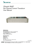
1
ITZ ULTRASTAB USER MANUAL 05January2012/Version 0 Page 1 of 29 TABLE OF CONTENTS TABLE OF CONTENTS .......................................................................................................................... 1 LIST OF FIGURES .................................................................................................................................. 3 LIST OF TABLES .................................................................................................................................... 3 DOCUMENT INFORMATION.................................................................................................................. 3 INTRODUCTION ..................................................................................................................................... 4 WARRANTY STATEMENT ..................................................................................................................... 5 RECEIVING AND UNPACKING .................................................................................................................. 6 GENERAL SPECIFICATIONS ................................................................................................................ 7 1 Compliance with regulations............................................................................................................ 8 2 Usage precautions and recommendations ...................................................................................... 9 2.1 Terms and symbols ................................................................................................................. 9 2.2 General use and wear ............................................................................................................. 9 2.3 Grounding considerations........................................................................................................ 9 2.4 Fuses ....................................................................................................................................... 9 2.5 Precautions for use ................................................................................................................ 10 3 Quick start...................................................................................................................................... 11 3.1 System overview.................................................................................................................... 11 3.2 Setting up............................................................................................................................... 11 4 Introduction .................................................................................................................................... 14 4.1 Main features ......................................................................................................................... 14 4.2 Standard transducer heads ................................................................................................... 14 4.3 Custom transducer heads ..................................................................................................... 15 4.4 Voltage output module ........................................................................................................... 15 4.5 Current transfer ratio and programmability ............................................................................ 15 4.6 Front ...................................................................................................................................... 17 4.7 Rear ....................................................................................................................................... 18 4.8 Transducer head ................................................................................................................... 19 5 Installation...................................................................................................................................... 20 5.1 Mounting requirements for the electronics unit ..................................................................... 20 5.2 Mounting requirements for the transducer heads.................................................................. 20 5.3 Grounding the transducer head ............................................................................................. 21 5.4 Installation.............................................................................................................................. 21 6 Offset adjustment .......................................................................................................................... 22 6.1 Adjusting the current offset .................................................................................................... 22 7. I/0-ports.......................................................................................................................................... 23 7.1 Analog Out connector ............................................................................................................ 23 7.2 4 mm “Banana” Current Output terminals ............................................................................. 23 7.3 Status/Interlock connector ..................................................................................................... 24 7.4 Transducer head connector................................................................................................... 24 Pin 8 Operating instructions ............................................................................................................ 25 8.1 Switching on power ............................................................................................................... 25 8.2 Using the ITZ ULTRASTAB in current mode ......................................................................... 25 8.3 Connecting directly to a current measuring device ............................................................... 25 8.4 Connecting to an external burden resistor ............................................................................ 26 8.5 Connecting the ITZ ULTRASTAB to a DMM or high impedance amplifier............................ 26 9 Theory of operation ....................................................................................................................... 27 9.1 Basic principle of ITZ ULTRASTAB current transducers ..................................................... 27 10 Maintenance .............................................................................................................................. 28 Appendix A: Declaration of conformity .................................................................................................. 29 05January2012/Version 0 Page 2 of 29 LIST OF FIGURES Figure 1: System overview .................................................................................................................... 11 Figure 2: Front panel of electronics rack ............................................................................................... 17 Figure 3: Back panel of electronic rack ................................................................................................. 18 Figure 4: Analog out connector pinout .................................................................................................. 23 Figure 5: Status/Interlock connector pin out .......................................................................................... 24 Figure 6: Wiring schematics to current measuring device .................................................................... 25 Figure 7: Wiring schematics to external burden resistor ....................................................................... 26 Figure 8: Wiring schematics to high impedance load ............................................................................ 26 Figure 9: Block diagram showing the zero flux detector principle ......................................................... 27 LIST OF TABLES Table 1 General specifications for electronics rack ................................................................................. 7 DOCUMENT INFORMATION 5.01.2012 Creation of user manual 05January2012/Version 0 Version: 0 Page 3 of 29 INTRODUCTION Congratulations with your purchase of LEM ITZ Ultrastab The ITZ Ultrastab system provides a flexible yet user-friendly platform for use in laboratory, test facility and industrial applications where the highest performance fluxgate current sensing is needed. The platform offers full-scale current sensing from 600 A and up to 24000 A by utilizing a broad range of compatible current measuring heads. Please read this manual carefully before use. It contains information on how to set up and use the ITZ Ultrastab and how to build an ultrahigh precision system. In case of unanswered questions do not hesitate to contact either LEM SA or our local distributor directly. IMPORTANT: LEM SA will not be held responsible for use of the ITZ Ultrastab unit under conditions and/or in application setups not supported by the information in this manual. 05January2012/Version 0 Page 4 of 29 WARRANTY STATEMENT 05January2012/Version 0 Page 5 of 29 RECEIVING AND UNPACKING The shipping material and the ITZ ULTRASTAB should be thoroughly inspected for signs of obvious physical damage immediately upon receipt. All materials in the package should be checked against the enclosed packing list and the list of standard delivery below. LEM SA will not be responsible for any shortages unless notified no later than 14 days after receiving. The LEM ITZ Ultrastab package should contain: Electronics 19 inch rack-mount ITZ Ultrastab Transducer head – depending on nominal current range European (Schuko) and US mains cable with three-pin IEC female connector Cable for connecting head and rack electronics Analog output cable Manual Calibration certificate IN CASE OF DAMAGE If the equipment is damaged in any way, a claim should be filed with the shipping agent, and a full report of the damage should be forwarded to LEM SA or our local representative immediately upon receiving. Upon receipt of this report, LEM SA will forward instructions concerning the repair, replacement or return shipment. Please include the Type No., Serial No., and Order No. for the ITZ Ultrastab on any communication with LEM SA or our local representative. 05January2012/Version 0 Page 6 of 29 GENERAL SPECIFICATIONS FOR RACK ELECTRONICS Electrical Data – MAINS INPUT Mains Input 100-240 V AC, 50/60 Hz Fuses 2.5 AT / 240 V AC Electrical data – ANALOG OUTPUT PORT Full-scale output current ±1 A (± 2 or ± 3 A) Full-scale output voltage ± 10 V Output impedance < 1 Ohm IEC-type inlet socket Internal fuses, not replaceable user- -S and –SB versions -SB versions -SB versions Electrical data – STATUS PORT 45 V Max collector-emitter voltage, off-state Max reverse collector5V emitter voltage, off-state Max collector-emitter 5 mA current, on-state On-state saturation <1 V collector-emitter voltage Physical data – Electronics rack Dimensions 480x88x430 mm Weight 8.4 kg (9.2-10.0kg) Operating conditions Temperature Humidity Cooling 10-40 deg. C 20-80% RH Internal fan Storage conditions Temperature Humidity -20-85 deg. C 20-80% RH WxHxD, incl. handles/connectors Value for 600-5000 A systems (10 kA/16 kA–24 kA systems) Table 1: General specifications for rack electronics 05January2012/Version 0 Page 7 of 29 1 Compliance with regulations FCC statement This equipment complies with the limits for a Class A digital device, pursuant to part 15 of the FCC Rules. These limits are designed to provide reasonable protection against harmful interference when the equipment is operated in a commercial environment. This equipment generates, uses and can radiate radio frequency energy and, if not installed and used in accordance with the instruction manual, may cause harmful interference in which case the user will be required to correct the interference at his own expense. CE statement This product has been tested and found to comply with the following standards. Electrical safety: IEC/EN 61010-1 Electromagnetic Compatibility: Emission: IEC/EN 61326-1:2006 FCC 47 CFR Part 15 Immunity: IEC/EN 61326-1:2006 A technical file is kept available at: LEM Danfysik A/S Hassellunden 16 DK-2765 Smoerum DENMARK 05January2012/Version 0 Page 8 of 29 2 Usage precautions and recommendations The following precautions are recommended to insure your safety and to provide the best operating conditions of this instrument. If this equipment is used in a manner not specified by the manufacturer, the protection provided by the equipment may be impaired. 2.1 Termsandsymbols These terms and symbols may appear in this manual or on the product. ! ! WARNING: Warning statement identifying condition or practices that could result in human injury or loss of life. CAUTION: Caution statement identifying conditions or practices that could result in damage to the product. DANGER: High Voltages. Protective Ground Conductor Terminal. 2.2 Generaluseandwear ! 2.3 CAUTION: Do not place any heavy objects on the instrument. Avoid severe impacts or rough handling that could damage the instrument. Use electrostatic discharge precautions while handling and making connections to the instrument. Do not place bare or unterminated wires into the connectors of the instrument, only mating connectors and adapters. Do not block or obstruct the ventilation openings on the side panels and over the heat sink. Grounding considerations To avoid the risk of electrical shock it is mandatory to observe proper grounding practices. ! WARNING: To avoid electrical shock the power cord protective grounding conductor must be connected to earth ground. All transducer heads must be connected to earth ground as described in section 5.3. Failure to establish a functional ground connection to earth may lead to hazardous errors and cause malfunction and/or measurement inaccuracies. 2.4 Fuses ! WARNING: The unit has no user replaceable fuses. In the event that fuses need replacement please consult your local LEM Sales representative. Please include Type and Serial no. with all communication with LEM SA or the local representative. 05January2012/Version 0 Page 9 of 29 2.5 Precautionsforuse Due to the nature of the zero-flux based transducer principle it is necessary to take the following precautions: ! ! CAUTION: Do not subject the system to primary current without mains power applied. CAUTION: Do not operate the system with a disconnected secondary when the system is subject to primary current. 05January2012/Version 0 Page 10 of 29 3 Quick start 3.1 System overview Figure 1: System overview 3.2 Setting up To quickly get your new ITZ ULTRASTAB system operational, follow the instructions given below. 1. Connect the transducer head to the unit using the supplied transducer head cable and mount the programming plug in the connector on the transducer head if your system has the programming feature – please note that not all transducer heads are programmable. 2. Connect a Digital Multimeter (DMM) to the unit. If your unit has current output (-S or –SPR versions): The primary access is through the Analog Output Port, using the Current Output Adaptor supplied with the ITZ system. 05January2012/Version 0 Page 11 of 29 The unit also has a secondary output through the 4 mm banana terminals on the back panel of the ITZ unit. Since the primary and secondary current outputs are connected electrically in series internal to the electronics the 4 mm banana terminals should be left shorted (using the supplied shorting plug) for this exercise. ! CAUTION: It is MANDATORY that the secondary current path remains CLOSED whenever the system is powered – if not, there is a risk of permanently damaging the system. Furthermore, if there is no closed secondary current path the system will not be able to produce measurable output. The secondary current path is closed either by shorting the 4mm banana terminals or by connecting a series (measuring) resistor at these outputs. Using standard 4 mm banana test leads, connect the red wire on the Current Output Adaptor to the current input terminal on the DMM and the black wire of the adaptor to the common terminal on the DMM. Set the DMM to measure DC current in a range greater than: ± 1 A for ITZ 600-SPR (-SBPR) and ITZ 2000-SPR (-SBPR) ± 2 A for ITZ 2000-S (-SB), ITZ 5000-S (-SB), ITZ 10000-S (-SB) and ITZ 16000-S (-SB) ± 3 A for ITZ 24000-S (-SB). IMPORTANT: Refer to page 23 for EMC precautions for the 4 mm banana terminal port. 05January2012/Version 0 Page 12 of 29 If your unit has a voltage output (-SB or –SBPR versions): Connect the Analog Output Cable to the Analog Output Port. Using standard 4 mm banana test leads, connect the red wire of the cable to the positive terminal on the DMM and the black wire to the common terminal. Set the DMM to measure DC/AC voltage in a range greater then ± 10 V. The blue wire of the cable is connected to the cable shield and to chassis ground. Make sure the supplied shorting plug is installed on the 4 mm banana terminals as described in the previous section. ! CAUTION: It is MANDATORY that the secondary current path remains CLOSED whenever the system is powered – if not, there is a risk of permanently damaging the system. Furthermore, if there is no closed secondary current path the system will not be able to produce measurable output. For voltage output versions this is ensured either by shorting the 4 mm banana terminals using the supplied shorting plug, by connecting a DMM in low-impedance current measuring mode or by connecting a measuring resistor to the 4 mm banana terminals. 3. Connect the mains cord. ! CAUTION: Since the ITZ system has no mains switch the unit will be powered immediately by inserting the mains cord. 4. The ITZ ULTRASTAB will now measure the current running through the transducer head. On the front plate the status of the unit can be monitored using the status LED panel. 05January2012/Version 0 Page 13 of 29 4 Introduction 4.1 Main features The ITZ ULTRASTAB is a high precision current measuring device based on the Flux-gate principle. It can measure current in both the DC and AC domain. The instrument can be configured in a variety of ways to suit the user’s demands. Amongst the ITZ ULTRASTAB main features are: Current or voltage output Input range from 0 to ± 24000 A Status signals for interfacing with other equipment The current measuring range is configurable depending on the transducer head. 4.2 Standard transducer heads ITZ ULTRASTAB can be delivered with the following transducer heads. 1. ITZ 600-25-PR – programmable (please refer to section 0) in steps of 20 A from 40 A to 620 A. Turns ratio (default) of 600:1. Nominal secondary current 1 A. Aperture Ø 25 mm 2. ITZ 2000-50-PR – programmable in steps of 125 A from 125 A to 2000 A. Turns ratio (default) of 2000:1. Nominal secondary current of 1 A. Aperture Ø 50 mm 3. ITZ 2000-50 – non-programmable, wide-bandwidth. Turns ratio of 1000:1. Nominal secondary current of 2 A. Aperture Ø 50 mm 4. ITZ 5000-140 – non-programmable. Turns ratio of 2500:1. Nominal secondary current of 2 A. Aperture Ø 140 mm 5. ITZ 10000-100 – non-programmable. Turns ratio of 5000:1. Nominal secondary current of 2 A. Aperture Ø100 mm 6. ITZ 16000-150 – non-programmable. Turns ratio of 8000:1. Nominal secondary of 2 A. Aperture Ø 150 mm 7. ITZ 24000-150 – non-programmable. Turns ratio of 8000:1. Nominal secondary of 3 A. Aperture Ø 150 mm Please note that systems are always downwards compatible in the sense that a smaller transducer head can be used with the rack electronics from a larger system. ie., if you have purchased an ITZ 10000-S system you will be able to use a 600 A transducer head with your rack electronics without any limitations. The system will adapt itself to this. 05January2012/Version 0 Page 14 of 29 However, the system is not generally upwards compatible. ie., you will not generally be able to use a larger head with the rack electronics from a smaller system. If you want to expand the measuring range of your system by using a larger transducer head, please consult your local LEM SA Sales representative to obtain information on existing options and cost. 4.3 Custom transducer heads For current measurement of 10 kA and beyond certain customizing may be required. Your local LEM SA Sales representative will be able to assist you with custom requirements for turns ratio, programmability options etc. 4.4 Voltage output module In addition to the different transducer heads a system can also be equipped with a VOM (Voltage Output Module). This module will convert the output current to an output voltage of ± 10 V (nominal full-scale). Three types VOMs are available, one for each nominal output current range (1, 2 or 3 A). In all cases, the output current is also available for monitoring either by the 4 mm banana jacks on the back panel or with the Analog Output Cable. If you have ordered your system with the “B” option (eg. ITZ 5000-SB), it already has a VOM installed. If your system was ordered as a standard current output system you can have a VOM retrofitted. Please contact your local LEM SA Sales representative to obtain information on existing options and cost. 4.5 Current transfer ratio and programmability The system can generally be considered as a “current transformer also working at DC”. The primary winding is the wire through the center hole of the head, and the secondary winding is the compensation winding of the transducer head. The ratio between these two windings defines the current transfer ratio ( N ) of the system. The smaller transducer heads come with a programming option. As the nominal output current ( I sn ) is fixed (defined by the transducer head) and the maximum input current ( I p ) can be changed using a programming plug, the current transfer ratio can be changed enabling the user to program the system to many different maximum input currents. 05January2012/Version 0 Page 15 of 29 Example: A system with an ITZ 2000-50 PR transducer head programmed to 1500 A will produce 1 A when the primary current is 1500 A. The current transfer ratio of the system is then: N Ip I sn 1500 A 1500 1A When a system is equipped with a VOM, the output current will be converted to a voltage. The maximum nominal output voltage ( Von ) is fixed at 10 V. Thus the ratio ( G ) from the example above can be found as: G Ip Von 1500 A 150 A V 10V 05January2012/Version 0 Page 16 of 29 4.6 Front 1 2 Figure 2: Front panel of electronics rack On the front of the ITZ ULTRASTAB there is an LED indicator panel: POWER: This LED is lit (Blue) when the unit is on. 1 ACTIVE: This LED is lit (Yellow) when the transducer output is active, with IP higher than approximately 1% of nominal full-scale output. HIGH IP: This LED is lit (Yellow) when the transducer output is active with an IP higher than 105% of nominal full-scale output. OVERLOAD: This LED is lit (red) when the transducer head saturates due to excessive primary current. 600A – 24000A: These LEDs are lit (Yellow) when a transducer head with the corresponding full-scale range is connected to the ITZ ULTRASTAB. CUSTOM: This LED is lit (Yellow) when the system setup has detected a custom head configuration. STATUS: This LED is lit (Green) when the status of the unit is OK. 2 Output current offset adjustment An offset adjustment is positioned next to the left-most handle. The adjustment is accessible using a miniature slotted screwdriver. ! CAUTION: Please refer to section 6 for instructions on how to adjust offset correctly. 05January2012/Version 0 Page 17 of 29 4.7 Rear 2 8 3 TRANSDUCER HEAD HEAD S/N: OPTION A UNIT S/N: LEM Danfysik A/S Hassellunden 16 DK-2765 Smoerum www.lem.com OPTION B VOM: Do not apply current to the transducerhead before MAINS INPUT is ON MAINS INPUT STATUS 100-240 VAC 50/60 HZ 300W (MAX) MONITOR + CURRENT - ANALOG OUT Do not connect or disconnect the transducerhead while MAINS INPUT is ON Unplug mains cable before removing cover 1 Figure 3: Back panel of electronic rack 7 6 5 All connections on the ITZ ULTRASTAB are located on the rear of the unit. 1. IEC power inlet: This connector accepts a standard IEC power cord. IMPORTANT: The power inlet also serves as mains switch. IMPORTANT: The unit operates with a universal mains input. This means that the unit does not require any switching between mains voltages as long as the supplied mains voltage is within 100-240 V AC (50-60 Hz). IMPORTANT: The unit has no externally accessible user-serviceable fuses. If the unit requires replacement of fuses please contact your local LEM SA sales representative. 2. Type / Serial number plate. Three individual S/Ns may be listed here: One for the ITZ electronics, one for the matching head and one (optional) for the installed VOM. 3. 4. 5. Transducer head: Connection to the transducer head. Analog out: Output connection to a DMM or other equipment. Current +/-: Secondary current output. ! 6. CAUTION: The secondary current path must be closed with the system powered. This includes both the current output in the Analog Out connector and the 4 mm banana terminals – if the latter are not used, please connect the supplied shorting plug. Monitor: Voltage output with a low-precision voltage output derived from the secondary current. Output is ± 1 V full-scale. Status/Interlock signal outputs. Option A+B: These positions are for future expansion or customization. 7. 8. Ventilation exit The main heat sink has an airflow exit centered on the back panel. Inlet holes are on the side panel of the chassis. ! CAUTION: Do not block the airflow to/from the unit. 05January2012/Version 0 Page 18 of 29 4 4.8 Transducer head The transducer head is connected to the electronics rack using a dedicated cable with a multi-pin bayonet-style connector. Various cable lengths are available. If the transducer head is programmable it also has a D-sub 25-pin male connector. This connector is used with suitable programming plugs (accessory) – for further information, please refer to section 4.5 for further information on programmability. ! CAUTION: A programming plug must be connected to the programming port of a programmable head when the system is powered. 05January2012/Version 0 Page 19 of 29 5 Installation 5.1 Mounting requirements for the electronics unit The ITZ ULTRASTAB can be mounted in either a rack based system or as a stand-alone unit using the supplied rubber feet. ! 5.2 CAUTION: The unit must be mounted horizontally. To ensure proper cooling, keep ventilated ides on side and back panel free. Failure to do this may result in improper cooling of the system which may lead to malfunction of the unit. Mounting requirements for the transducer heads ITZ 600-25-PR: Use the mounting bracket (part no.: 7100088284) to mount the 600 A transducer head. It may be installed in any orientation. ITZ 2000-50 (-PR): The 2000 A transducer head must be installed using two M8 screws. The head may be mounted in any orientation. Please observe that the length of the screws may not exceed the length D shown in figure 5. To calculate the maximum length of the mounting screw, measure the thickness of the mounting substrate C and add the length A + B which is 10 mm + 15 mm. Max. Screw length: D = 10 + 15 + C [mm] Transducer core A D B C 10 15 Mounting plate Mounting substrate Mounting screw Figure 5 CAUTION: Using too long screws may cause damage to the inner parts of the transducer head and lead to malfunction. ITZ 5000-140, ITZ 10000-100, ITZ 16000-150, and ITZ 24000-150: These transducer heads are mounted using four M10 screws inserted into the holes on the brackets. These heads may be installed in any orientation. 05January2012/Version 0 Page 20 of 29 5.3 Grounding the transducer head For safety reasons all types of transducer heads must be properly grounded. Follow the description below for the appropriate transducer head in order to establish a good grounding connection. ITZ 600-25-PR: A Ground wire (min 1.5 mm2) with an Ø 4.3 mm ring tongue must be connected to the transducer head. The ring tongue is fastened to the M4 stud in the lower rightmost corner of the STH600 using a M4 nut. ITZ 2000-50 (-PR): A ground wire (min 1.5 mm2) with an Ø 8.3 mm ring tongue must be connected to the transducer head. The ring tongue is placed on one of the 4 mounting screws before mounting the head. ITZ 5000-140, ITZ 10000-100, ITZ 16000-150, and ITZ 24000-150: A Ground wire (min 1.5 mm2) with an Ø 10.3 mm ring tongue must be mounted to the transducer head. The ring tongue is placed on one of the 4 mounting screws before mounting the head. 5.4 Installation 1. Establish the ground connection (see section 5.3). 2. Mount the provided connection cable between the ITZ ULTRASTAB electronics and transducer head. 3. Connect the Analog Output Cable as described in section 8.3-8.6. 4. Check that all cables terminated in a plug are correctly installed and that the lock screws are tightened firmly. 5. Connect the supplied power cord to the IEC inlet on the unit to turn it on. The transducer head and electronics can be installed with a transducer head connecting cable of 30 meters maximum. 05January2012/Version 0 Page 21 of 29 6 Offset adjustment The ITZ ULTRASTAB should occasionally have a current offset adjustment made to ensure the highest accuracy. All ITZ ULTRASTAB are offset adjusted with the accompanying transducer head prior to shipment from the factory. In case the ITZ ULTRASTAB system has been recalibrated or serviced, and as a minimum after half a year of operation, it is advisable to perform an offset adjustment with the selected transducer head connected prior to any measurement in order to achieve the highest accuracy. 6.1 Adjustingthecurrentoffset To adjust the ITZ ULTRASTAB please follow these steps. 1. Connect a DMM capable of measuring microamps (µA) to the Analog output port using the current output adaptor cable. 2. Connect the mains cord to the IEC inlet. 3. Wait for approx. 15 minutes after powering up the system for the unit to stabilize thermally. 4. Locate the offset trim hole on the front of the electronics unit (lower left corner). 5. Use a trim screwdriver to adjust the offset until the current is as close to zero as possible. 05January2012/Version 0 Page 22 of 29 7. I/0-ports 7.1 AnalogOutconnector Normally an appropriate output cable should be used, depending on whether your system has current or voltage output. It is also possible to configure your own output cable, bearing the following description in mind. The Analog out connector (Dsub15-F) contains the following signals: 1. Current return 2. Current return 3. Current return 4. Vo High Sense 5. Vo High Out 6. Ground 7. Vo Low Sense 8. Vo Low Out 9. Current out 10. Current out 11. Current out 12. Vo High Sense 13. Vo High Out 14. Vo Low Sense 15. Vo Low Out 1 9 8 15 Figure 4: Analog out connector pinout When using the ITZ ULTRASTAB in current out mode (no VOM installed) only pin 1, 2, 3 and 9, 10, 11 should be used. Pin 9, 10, 11: Is the current output from the ITZ ULTRASTAB. Pin 1, 2, 3: Current return path. When using the ITZ ULTRASTAB in voltage out mode (VOM installed) pin 1– 9, pin 2–10 and pin 3-11 must be shorted. This will loop the current output to the VOM. The voltage output is then present at pin 4 - 8 and 12 - 15. IMPORTANT: The sense pins (Vo High Sense on pin 4 and 12, and Vo Low Sense on pin 8 and 14) must be connected to Vo High Out and Vo Low Out respectively. 7.2 4 mm “Banana” Current Output terminals Two standard 4mm banana jacks are available for easy connection to a low impedance current measuring DMM. ! CAUTION: These terminals should be shorted when not in use by use of the supplied shorter plug. IMPORTANT: The ITZ system is tested for EMI conformance against industrial standards. Use of the unshielded 4mm banana current output port can be critical under circumstances with a high level of external disturbance. 05January2012/Version 0 Page 23 of 29 7.3 Status/Interlock connector All signals on the Status/Interlock connector are optically isolated, opencollector types. The four signals are present on the connector, each having two dedicated pins: collector (C) and emitter (E). The signals are “active low”, meaning that an active signal will draw current from collector to emitter. OVERLOAD HIGH IP ACTIVE STATUS Active low when the transducer head is saturated due to excessive primary current. Pin 1: C Pin 6: E Active low when the transducer output is active with an IP higher than 105% of nominal fullscale output. Pin 2: C Pin 7: E Active low when the transducer output is active, with an IP higher than approximately 1% of nominal full-scale output. Pin 3: C Pin 8: E Active low when the status of the unit is OK. Pin 4: C Pin 9: E 1 5 6 9 Figure 5: Status/Interlock connector pin out 7.4 Transducer head connector The circular multi-pin bayonet-style connector is used to connect the transducer head to the electronics. It is critical to ensure the signal integrity in this I/O interface in order to maintain the very high performance level this system can achieve. As a consequence, pins in this I/O interface are not available for the user. 05January2012/Version 0 Page 24 of 29 Pin 8 Operating instructions 8.1 Switching on power ! CAUTION: Before switching on the power make sure that there is no current running through the transducer head. IMPORTANT: The ITZ rack electronics has no MAINS switch. To power off the unit disconnect the mains plug at the power inlet. Before powering up the ITZ ULTRASTAB be sure to check the following: 1. Check that all cables terminated in a plug are correctly installed and that the lock screws are tightened firmly 2. Check that the system is properly grounded through the mains connection and that the transducer head is grounded according to the directions given in section 5.3. 3. Connect the power cord to the mains inlet 4. The ITZ ULTRASTAB will now run through its power up sequence. After a few second the unit is ready and the status of the unit can be seen on the front panel LEDs 5. Switch primary current on. The ACTIVE LED will turn on. 8.2 Using the ITZ ULTRASTAB in current mode When using the ITZ ULTRASTAB without a VOM installed there are essentially two ways to measure the output. It can either be connected to a current measuring device or to an external burden resistor. 8.3 Connecting directly to a current measuring device Connecting the ITZ ULTRASTAB directly to a current measuring device like a DMM or a power analyser, can easily be done from the current output port with two standard 4 mm banana plugs. Take care that both terminals are floating relative to ground. The red wire carries the output current while the black is the current return path. Simply connect these two wires to your current measuring device using standard laboratory test leads with 4mm banana terminals. Figure 6: Wiring schematics to current measuring device 05January2012/Version 0 Page 25 of 29 8.4 Connecting to an external burden resistor If an external burden resistor is to be connected to the ITZ ULTRASTAB the connection shown below should be used. Figure 7: Wiring schematics to external burden resistor In addition to the standard current output cable of 1.5 m length a 5 m long current output cable is also available. Both cables use two twisted pairs in order to reduce the resistance, and are terminated in three 4 mm female banana sockets for easy connection to other equipment. 8.5 Connecting the ITZ ULTRASTAB to a DMM or high impedance amplifier When connecting the ITZ ULTRASTAB to a DMM or high impedance load in voltage mode (VOM installed) use the connection shown below. This diagram is equal to the standard voltage output cable. This cable uses a single twisted pair, and is terminated in three female banana sockets for easy connection to other equipment. Figure 8: Wiring schematics to high impedance load 05January2012/Version 0 Page 26 of 29 9 Theory of operation 9.1 Basic principle of ITZ ULTRASTAB current transducers The ITZ ULTRASTAB current transducers are delivered in a series covering galvanic isolated measurements of currents from DC to 500 kHz ranging from 40 A to 24 kA. These precision current transducers use a zero flux detector principle controlling a compensation current which counterbalances the ampere-turns generated by the primary current. Due to a balanced zero flux detector principle the output noise level is extremely low by nature and a resolution on the order of 2 x 10⁻⁸ is achieved. Below is shown a block diagram of the zero flux detector principle. Figure 9: Block diagram showing the zero flux detector principle The transducer head core (1) is the basic body structure. The cores (2) and (3) are the flux detectors coupled to the zero-flux detector circuitry by means of the coils L1 and L2. Coils L1 and L2 are coupled in parallel or series depending on the model, with opposite phase to reduce any unwanted flux generated in core 1. 05January2012/Version 0 Page 27 of 29 With primary current (Ip) flowing through primary winding L4, a magnetic flux will be generated in the body structure and detected by the detector cores. An error signal will be generated, controlling the amplifier A1 to drive a current through the compensation, winding L3. When counterbalance is obtained, i.e. zero flux is re-established, the compensation current, multiplied by the number of turns in winding L3, is a true representation of the instantaneous primary current (Ip) . The zero flux detector circuitry operates from true DC to about 1 Hz. For higher frequencies the “AC pick up” winding L5 performs as a feedback error signal via the amplifer A3 which widens the active bandwidth of the transducer to more than 10 kHz. Above 10 KHz the Define CCT the transducer operates as a passive current transformer with its -3 dB limit varying from 300 KHz to 1 MHz depending on the size and construction of the head. 10 Maintenance The ITZ ULTRASTAB with current output does not require any maintenance under normal operation except for the offset adjustment explained in section 6. The ITZ ULTRASTAB with voltage output requires offset adjustment as described in section 6. The system is a calibrated entity that should be recalibrated every 2 years to ensure the calibration level of the system. To get your ITZ ULTRASTAB recalibrated we recommend shipping it to LEM Danfysik A/S. If the unit needs service please contact LEM Danfysik A/S or our local sales representative. 05January2012/Version 0 Page 28 of 29 Appendix A: Declaration of conformity 05January2012/Version 0 Page 29 of 29