1
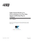
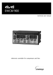
bus
VT1532A
Eight-Channel Current Output Signal
Conditioning Plug-on
User’s Manual
Enclosed is the User’s Manual for the VT1532A Signal Conditioning Plug-on. Insert
this manual in your VXI Module’s User’s Manual behind the “Signal Conditioning
Plug-ons” divider.
APPLICABILITY
This SCP is used with the VT1415A and VT1419A.
Copyright© VXI Technology, Inc., 2003
Manual Part Number: 82-0090-000
Printed: June 9, 2003
Printed in U.S.A.
VT1532A
Eight-Channel Current Output
Signal Conditioning Plug-on
Introduction
The VT1532A provides an eight channel non-isolated current source. Each
output can source ±10 mA with up to ±15 volt compliance. Each VT1532A
output can detect an over-voltage condition.
About this Manual
This manual shows you how to control the Signal Conditioning Plug-on
(SCP) using SCPI commands and explains the capabilities of this SCP. The
contents of this manual are:
·
·
·
·
·
·
·
·
·
·
Installation . . . . . . . . . . . . . . . . . . . . . . . . . . . . . . . . . . . . .
Identifying the Plug-on . . . . . . . . . . . . . . . . . . . . . . . . . . .
Field Wiring . . . . . . . . . . . . . . . . . . . . . . . . . . . . . . . . . . . .
Programming With SCPI Commands . . . . . . . . . . . . . . . .
Programming with the Algorithm Language . . . . . . . . . . .
Sensing Output Current . . . . . . . . . . . . . . . . . . . . . . . . . . .
Over-Voltage Protection . . . . . . . . . . . . . . . . . . . . . . . . . .
*RST and *TST? (important) . . . . . . . . . . . . . . . . . . . . . .
SCP Calibration . . . . . . . . . . . . . . . . . . . . . . . . . . . . . . . . .
Specifications . . . . . . . . . . . . . . . . . . . . . . . . . . . . . . . . . . .
3
3
4
5
5
6
7
7
7
8
Installation
Installation for this Plug-on is common to several others and is covered in
Chapter 1 of your VXI Module User’s Manual.
Identifying the Plug-on
You’ll find the VTI Technology part number on the connector side of the SCP
to the left of the serial number bar code. For the VT1532A, the part number is:
VT1532A.
VT1532A Current Output SCP 3
Field Wiring
Since this Current Output SCP is NOT ISOLATED, it is extremely important
not to introduce ground current loops in the individual channel wiring. To
avoid this, make sure you follow the recommended wiring diagram that
follows.
VT1532A Channel
current output
Good
HI
Isolated
Input
Actuator
Shielded Twisted Pair
LO
chassis ground
Guard
VT1532A Channel
current output
Good
HI
Shielded Twisted Pair
Isolator
LO
Non-Isolated
Actuator
chassis ground
Guard
VT1532A Channel
current output
Not Recommended
HI
Shielded Twisted Pair
Non-Isolated
Actuator
LO
chassis ground
Guard
Voltage difference between
these grounds causes current
and offset voltage in LO wire
Figure 1 Recommended Field Wiring
4 VT1532A Current Output SCP
The following table maps SCP channels to Terminal Module terminal names.
Also see the Terminal Module labels supplied with your VT1532A.
SCP’s
Channel
SCP 0
channels
SCP 1
channels
SCP 2
channels
SCP3
channels
SCP 4
channels
SCP 5
channels
SCP 6
channels
SCP 7
channels
0 HI & LO
0H&L
8H&L
16 H & L
24 H & L
32 H & L
40 H & L
48 H & L
56 H & L
1 HI & LO
1H&L
9H&L
17 H & L
25 H & L
33 H & L
41 H & L
49 H & L
57 H & L
2 HI & LO
2H&L
10 H & L
18 H & L
26 H & L
34 H & L
42 H & L
50 H & L
58 H & L
3 HI & LO
3H&L
11 H & L
19 H & L
27 H & L
35 H & L
43 H & L
51 H & L
59 H & L
4 HI & LO
4H&L
12 H & L
20 H & L
28 H & L
36 H & L
44 H & L
52 H & L
60 H & L
5 HI & LO
5H&L
13 H & L
21 H & L
29 H & L
37 H & L
45 H & L
53 H & L
61 H & L
6 HI & LO
6H&L
14 H & L
22 H & L
30 H & L
38 H & L
46 H & L
54 H & L
62 H & L
7 HI & LO
7H&L
15 H & L
23 H & L
31 H & L
39 H & L
47 H & L
55 H & L
63 H & L
Programming With SCPI Commands
The only SCPI command shown here is used to query the SCP’s identification
string. Your VXI Module may or may not support SCPI commands to control
the SCP’s output amplitude. Check for OUTPut subsystem commands in the
SCPI Command Reference of your VXI Module’s User’s Manual.
Checking the ID
of the SCP
To verify the SCP type(s) installed on your VXI module, use the
SYSTem:CTYPe? (@<channel>) command.
· The channel parameter specifies a single channel in the channel range
covered by the SCP. The first channel number for each of the eight SCP
positions are; 0, 8,16, 24, 32, 40, 48 and 56.
The value returned for the VT1532A SCP is:
HEWLETT-PACKARD,E1532A 8-Channel Current Output SCP,0,0
To determine the type of SCP installed on channels 0 through 7 send
SYST:CTYP? (@100)
query SCP type @ ch 0
enter statement here
enter response string
Programming with the VT1415A Algorithm Language
The following example shows the command sequence (platform/language
independent) to send values to the SCP output channels. It assumes the SCP is
installed in SCP position 0. Use SCP positions 4 - 7 for the VT1419A
alg_string = “
first algorithm source in string variable
static float chan_0, chan_1, chan_2, chan_3; /* define algorithm variable. these*/
static float chan_4, chan_5, chan_6, chan_7; /* will default to zero at first */
O100 = chan_0;
/* algorithm execution */
O101 = chan_1;
O102 = chan_2;
O103 = chan_3;
VT1532A Current Output SCP 5
O104 = chan_4;
O105 = chan_5;
O106 = chan_6;
O107 = chan_7; ”
ALG:DEF ‘ALG1’,’alg_string’
send SCPI command to define algorithm “ALG1”
INIT
start algorithm (using default trig sys setup)
Algorithm sets starting channel values to zero. The following example shows how your
application program can change channel output values while the algorithm is running
ALG:SCALAR ‘ALG1’,’chan_0’,-0.010
ALG:SCALAR ‘ALG1’,’chan_1’,0.010
ALG:SCALAR ‘ALG1’,’chan_2’,0.005
ALG:SCALAR ‘ALG1’,’chan_3’,-0.001
ALG:SCALAR ‘ALG1’,’chan_4’,0.008
ALG:SCALAR ‘ALG1’,’chan_5’,0.010
ALG:SCALAR ‘ALG1’,’chan_6’,-0.095
ALG:SCALAR ‘ALG1’,’chan_7’,0.000
ALG:UPDATE
must command VT1415A to update the algorithm variable
Sensing Output Current
Each channel has a 69 Ohm current sense resistor in series with its output. The
analog input channel associated with each output channel is connected across
this current sense resistor. Reading a channel returns the voltage developed
across its current sense resistor. The value input from these channels is related
to the output current by the formula:
Current =
VoltageRead
69
for example:
O100 = current_output /* program the output current for channel 0 */
readback = I100 / 69
/* current sense channel divided by 69 Ohms */
Notes
1. This readback value is only an approximation of the actual output current.
The SCP’s output current is calibrated to specification each time you
execute the *CAL? command. The input channels for this SCP are not
calibrated by *CAL?. The programmed current output value will be more
accurate than the sense value. The sense value is used only to verify the
approximate programmed current.
2. An overload reading returned from one of the sense channels does not
indicate an overcurrent condition. It indicates that the channel’s HI terminal
has exceeded the voltage input range of the channel. This can occur when
the channel output is programmed to 0 but is not connected to a load. This
will occur when the channel is programmed to output current and is not
connected to a load.
6 VT1532A Current Output SCP
Over-Voltage Protection
As was mentioned in the first paragraph, the VT1532A can sense an
over-voltage condition on any of its outputs. This is to protect the SCP and the
module it is installed on from damaging voltage levels applied to its outputs.
If greater than approximately 21 volts is applied to an output channel, the SCP
may signal the VXI module to open all of its Calibration/Protection relays.
The module will then generate an error message in its error queue (read by
SYST:ERR?) and set a status bit in its STAT:QUES:COND register.
Note
The over-voltage protect condition can only be reset by issuing the command
*RST or by cycling power to the module.
*RST *CAL? and *TST? (Important!)
During execution of *RST, *CAL? and *TST?, the outputs of the VT1532A
will be disconnected momentarily from your system. When the operation is
completed, outputs will be programmed to output approximately 0 mA. The
*RST command is typically used at the beginning of all application
programs. Make sure the design of your system takes into account this *RST
behavior.
SCP Calibration
The VT1415A calibrates all channels of this SCP when the *CAL? or
CALibration:SETup commands are sent. If this SCP is replaced with a
different VT1532A or this SCP is moved to a different SCP location, the
calibration must be repeated. By default, the VT1415A uses the Least
Squares Curve Fitting method to determine the gain and offset calibration
constants for each VT1532A channel. This maximizes the overall channel
accuracy (see “Voltage Output Accuracy” in specifications section).
Because the Least Squares Curve Fit method does not force the output at a
programmed zero to be zero, there can be up to 3.3 µA error at this point. By
sending then DIAG:CAL:SETUP 1 command before you send the *CAL?
or CAL:SET commands, all VT1532A and VT1531A outputs will be
calibrated to reduce the error at their programmed zero point. The trade-off is
that this can approximately double the error at the VT1532A’s ±125 µA
point. The specifications then become ±0.06% of expected output ±5.7 µA
offset. DIAG:CAL:SETUP 1 or *RST before the next *CAL? restores the
Least Squares Fit calibration.
VT1532A Current Output SCP 7
Specifications
These specifications for the VT1532A reflect its performance while installed
on your VXI module. These specifications are not to be added to those
presented in your VXI module User’s Manual.
General Specifications
Damage level: >±42 V peak
Maximum voltage applied to any
output Hi terminal
Current Output Range
at least ±10 mA Full Scale at greater than ±15 Volt compliance
(multiple channels can be connected in parallel to provide additional current.)
16 bits (monotonic to 16 bits) = 316 nA
Current Resolution
greater than ±600 kW
Output Impedance
<2 µA rms (20 Hz - 250 kHz, into 250 W)
Noise
350 µs with 250 W load
Output Settling Time
(for change in temperature from *CAL after 1 hr. warm up)
Accuracy: ±0.004%/°C
Offset Error: 0.3 µA/°C
Temperature Coefficient
Current Output Accuracy
Power Required
8 VT1532A Current Output SCP
(90 days) 23°C±1°C (with *CAL? done after 1 hr warm up and applied load is 500 W )
(±0.06% of expected output)±(3.3 µA Offset Error)
+5 Volts:
Typical 11 mA, Maximum 15 mA
±24 Volts:
With 0 mA into 250 W: Typical 60 mA, Max 75mA
With outputs at 10mA: Typical 135 mA, Max 150 mA