1
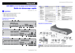
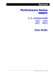
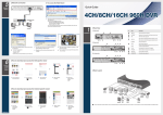
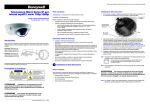
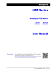
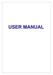
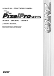
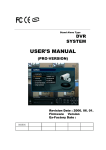
Performance Series HREP2 DVR Quick Start Guide Performance Series HREP2 4-, 8-, and 16-Channel DVR Quick Start Guide Document 800-15801 — Rev A — 12/2013 Table 1 No. Name Description No. Name Description 1 VIDEO IN Video input terminal for cameras. 8 USB Used for connecting USB storage or mouse. MONITOR H Monitor video output port. 9 eSATA Connection port for external eSATA storage. SPOT OUT Exclusive port for SPOT output only (use HDMI cable to connect to an HD monitor). 10 HD-MONITOR HD monitor video output port. 11 VGA VGA monitor video output port. 3 AUDIO IN Port for audio input. ALARM IN Alarm input signal port 4 AUDIO OUT Port for speaker connection. RELAY 1/2 Relay terminal output port. 5 DC 12V Power input port. Connect to a 12V adapter. RS-485 DIP Switch Switch to change unit’s video standard between NTSC and PAL. Ports for communication with external devices such as PTZ camera and system keyboard. WAN(UPLINK) Network port for connection to the Internet, router or hub. RS-232 Connection ports for signal cables to external devices such as PTZ camera, POS and ATM devices. 2 1 Installation The Performance Series HREP2 DVRs come in three offerings: • HREP24, 4-channel Digital Video Recorder • HREP28, 8-channel Digital Video Recorder • HREP216, 16-channel Digital Video Recorder 6 Rear Panel Connections 7 HREP24, 4-channel DVR Rear Panel Connections 12 Port for connecting the dedicated network device. LAN(DOWNLINK) 1 2 Note Do not share it with other device. 3 Basic System Layout 6 4 10 11 12 8 7 5 8 7 HREP28, 8-channel DVR 1 2 3 12 4 11 10 9 6 5 HREP216, 16-channel DVR 1 2 3 4 Note Signal connection for POS and ATM is scheduled to be upgraded later. 12 11 10 9 8 7 6 5 Document 800-15801 – Rev A – 12/2013 CAUTION Since the cable quality may affect directly to the video quality depending on the distance between the camera and DVR, it is recommended to consult an authorized installer when installing the DVR. 2 Getting Started Item (cont’d) Go to the PTZ screen. You can control the PTZ operations of a PTZ-compliant camera on the PTZ screen. Logging In 1. When the system starts, the login screen appears. 2. Select the user ID and enter the password. Note Double-click the timeline to move to the Playback mode. Drag and drop it to make a backup or event search for the specified area. Language Setting Zoom in or out on the selected video image. Display the log list of recent recording events. You can use the camera supporting the audio input to listen to the audio. The default user ID is ADMIN. The default password is 1234. 3. Description Start the emergency recording. Click OK. Blinks when an event occurs. It will not blink if no action to the event has been set. Click to view information about the event that occurred. CAUTION For safe and secure use of the product, change the password after purchasing. Check if the network connection is made through an external PC or mobile device. Click this to view the details of the concurrent users and to check the network connection status. Live Screen Video window Quick menu Time line Show the disk space information. If you have set the disk to overwrite mode, it will be displayed "OW" (Over Write) from the starting point of the overwriting. 1. Press SETUP on the remote control, or select MENU SYSTEM SETUP from the status bar. 2. From SYSTEM SETUP DISPLAY, select OSD. 3. Select a preferred language from the language drop-down list. Options are: English (default), French, Spanish, Italian, Dutch, German, Czech, Polish, and Russian. 4. Click APPLY. Shows the current date and time. Quick Menu Item Description Channel Number Display the number of the currently displayed channel. Play Start playing the video of the selected channel from the specified time. Zoom Move to the digital zoom setting. Snapshot Capture Capture the current live video and save it in the JPEG format. Status bar Item Timeline Item Description Select one of the System setup, Search and Backup menu items to access them. Timeline Date Display the date of the current timeline. Click this button to select a different date for the timeline. Show the ID of the user who is currently logged in. Zoom in/out of Timeline Expand or collapse the timeline. Edit the screen layout to show video in full screen mode, or to show the video along with the status bar and timeline. Navigation through Timeline Use these icons to select the split screen mode to view video with (choose from single, quad, 9-panel or 16-panel screens). Move to the previous or next point of time in the timeline. You can also use the mouse wheel to navigate through the timeline. Timeline Bar Represents the recorded data. The color of each bar indicates: • Green: Continuous Recording • Red: Alarm Recording • Blue: Motion Recording • Yellow: Panic Recording Display or hide the on-screen display (OSD) menus on the screen. Press SETUP on the remote control, or select MENU SYSTEM SETUP from the status bar. 2. From SYSTEM SETUP SYSTEM, select DATE/TIME. 3. From this screen, you can specify the format that the current time and date will be displayed. You can also setup network time synchronization, the timezone and daylight savings time settings. CAUTION As the existing data in the same time and date will be deleted if duplicates are found, back up the existing data for later use. Description Select Auto Sequence Mode. When a user arranges channels on desired tiles on a split screen view, this setting is listed for later selection. Selecting a screen setup directly switches the screen mode as configured. 1. Note After capturing the image, you can save it to the hard drive or export it to an external USB memory device. Status Bar Besides the remote control buttons, you can also use the status bar to control the DVR. Date/Time Setting 4. Click APPLY. Performance Series HREP2 DVR Quick Start Guide 3 Recording Setting the Network Connection 1. Connect the WAN(UPLINK) port in the rear panel of the DVR to any port available except for the WAN port of the router. 2. Connect the WAN(UPLINK) port of the router directly to the fixed IP LAN cable, or connect it to the xDSL modem. 3. Check the network address information if using a network environment connected to the same router. 4. Enter the network setting menu of the DVR and provide the IP address and other network settings (see Configuring Network Settings on page 3). Automatic Recording Setting 1. Press MENU on the remote control, and use the direction buttons to select RECORD SETUP and press ENTER. Alternatively, you can select MENU RECORD SETUP from the status bar. 3. You can identify the type of the recording data by the color in the bar: • 2. Set the RECORDING CONFIGURATION MODE to AUTO CONFIGURATION. 3. Select an AUTOMATIC RECORD CONFIGURATION MODE from the following options: • 4. • MOTION RECORD: Recording will proceed only if motion is detected. • ALARM RECORD: Recording will proceed only if an alarm event occurs. • MOTION/ALARM RECORD: Recording will proceed only if motion is detected or an alarm event occurs. • INTENSIVE MOTION RECORD: Normally recording will be performed in a low quality. However, the quality will switch to high if a motion is detected. • INTENSIVE ALARM RECORD: Normally recording will be performed in a low quality. However, the quality will switch to high if an alarm event occurs. • INTENSIVE MOTION/ALARM RECORD: Normally recording will be performed in a low quality. However, the quality will switch to high if an alarm event occurs or a motion is detected. Configuring Network Settings a. From the main menu of the DVR, navigate to SYSTEM SETUP NETWORK IP SETUP. • Green (Continuous): The continuous recording is performed on the recording data. b. Uncheck the DHCP checkbox and provide the necessary information in the required fields. • Red (Alarm): The alarm event recording is performed on the recording data. c. • Blue (Motion): The motion event recording is performed on the recording data. Check the network address information in the network environment settings and enter the correct information into the following fields: • Yellow (Panic): The panic manual recording is performed on the recording data. • IP ADDRESS: (enter the IP address to use for the DVR). • GATEWAY: 192.168.0.1 (enter the gateway address). 4. Click to move to a desired start time in the time bar, or use the buttons at the bottom of the status bar to make a search. • SUBNET MASK: 255.255.255.0 (type the subnet mask). • 5. Select an item to play and click PLAY. 1ST, 2ND DNS SERVER: 168.126.63.1 (enter the address of a DNS server). CONTINUOUS RECORD - ALWAYS HIGH VIDEO QUALITY: Recording will proceed in the best quality regardless of the event at all times. As this option will always make recording in the best quality, the recording period is the shortest compared to the other record modes. Yellow Green (Pre Recording): The pre-recording is performed on the recording data after you set the PRE RECORDING TIME from OPERATION MODE. CAUTION Click to move to a desired time, or simply doubleclick a desired time in the time bar to play the video data on that time. Note For details on thumbnail search and event search, refer to the user manual. 5 Network Setting Click APPLY. Note Enter an IP address that falls in the private IP range provided by the router (for example: 192.168.1.2~254, 192.168.0.2~254, and so on). 4 Searching d. When done, configure the port forwarding for RTSP and Web Service ports by clicking Port Forwarding. The default value of the Web service port is 8080. Time Search e. Click PORT FORWARDING for each. You will see the confirmation message. 1. From the SEARCH menu, select TIME SEARCH. f. Click APPLY and exit the menu. The network settings of the DVR are complete. 2. Specify the search date and time from the calendar in the left corner of the screen. Note Some router models may not support UPNP properly. If you see a failure message after configuring PORT FORWARDING settings, refer to the user manual of the router and configure the DMZ or port forwarding settings manually. 6 Accessing the Mobile Viewer Continue Setting the Network Connection – DDNS 1. When the network configuration is complete (see Configuring Network Settings on page 3), proceed with the DDNS settings to allow access to the DVR from outside. From the main menu of the DVR, move to SYSTEM SETUP NETWORK DDNS. 2. 3. Downloading and Accessing iOSSpecific Viewer 1. From your iPhone or iPad, access the App store. 2. From the lower menu bar, click the Search icon. 3. Type HREP2 in the search bar. Rename the DVR. (The default name of the DVR is the MAC address of the DVR.) 4. Select HREP2 to install it. Enter a desired name as a combination of characters and numbers. 5. When the installation is finished, select HREP2 again to run the program. When done, click DDNS REGISTRATION TEST and DDNS CONNECTION TEST in this order. Check the DVR address and the Web service port in the network settings to make sure that any Internet-connected PC can access the DVR. 5. If you type mydvr for the DVR name from the DDN item, the address of the Web viewer is http://mydvr.dvrlink.net: 8080. Accessing the Web Viewer Downloading and Accessing AndroidSpecific Viewer 1. Open the browser and enter the IP address of DVR, or enter the URL address in the address bar. 1. From your smart phone, access the android market. For example, if you use the DDNS of the DVR: http://00115f123456.dvrlink.net :8080 2. From the top menu bar, click the Search icon. If you do use the IP address of the DVR: http://192.168.0.210 : 8080 3. Type HREP2 in the search bar. 4. Select HREP2 to install it. 5. Click Accept & download to install the viewer. 6. You can run the remote viewer program after installation is complete. For more information about the router and network settings, refer to the user manual included with your unit. 2. When the login dialog appears, enter the user name and password. Note The default user name and password: • User name: ADMIN • Password: 1234 Be aware when you enter the user name whether it is upper or lower case. 3. Click the upper warning bar to install the ActiveX before enabling the add-in function. 4. When the security warning window appears, click Install. 5. When the ActiveX is installed completely, you will see the live screen. Note For more information about using the Web viewer, refer to the user manual. Canadian Compliance Statement This Class A digital apparatus complies with Canadian ICES-003. Cet appareil numérique de la Classe A est conforme à la norme NMB-003 du Canada. Manufacturer’s Declaration of Conformance North America The equipment supplied with this guide conforms to UL 60950-1 and CSA C22.2 No. 60950-1. Europe If you receive a success message. Check the DVR address and click APPLY at the bottom of the screen. 4. Note Changes or modifications not expressly approved by the party responsible for compliance could void the user’s authority to operate the equipment. The manufacturer declares that the equipment supplied with this guide is compliant with the essential requirements of the EMC directive 2004/108/EC and the Low Voltage Directive (LVD) 2006/95/EC, and the RoHS Directive 2011/65/EU, conforming to the requirements of standards EN 55022 for emissions, EN 50130-4 for immunity, EN 60950 for Electrical Equipment safety, and EN 50581 for assessment of electrical and electronic products with respect to the restriction of hazardous substances. CAUTION To comply with EN50130-4 requirements, a UPS should be employed. WARNING This is a Class A product. In a domestic environment this product may cause radio interference in which case the user may be required to take adequate measures. Waste Electrical and Electronic Equipment (WEEE) Correct disposal of this product (applicable in the European Union and other European countries with separate collection systems). This product should be disposed of, at the end of its useful life, as per applicable local laws, regulations, and procedures. Regulatory Statements FCC Compliance Statement Information to the User: This equipment has been tested and found to comply with the limits for a Class A digital device, pursuant to Part 15 of the FCC Rules. These limits are designed to provide reasonable protection against harmful interference when the equipment is operated in a commercial environment. This equipment generates, uses, and can radiate radio frequency energy and, if not installed and used in accordance with the instruction manual, may cause harmful interference to radio communications. Operation of this equipment in a residential area is likely to cause harmful interference in which case the user will be required to correct the interference at his own expense. www.honeywell.com/security +1 800 323 4576 (North America only) https://www.honeywellsystems.com/ss/techsupp/index.html Document 800-15801 – Rev A – 12/2013 © 2013 Honeywell International Inc. All rights reserved. No part of this publication may be reproduced by any means without written permission from Honeywell. The information in this publication is believed to be accurate in all respects. However, Honeywell cannot assume responsibility for any consequences resulting from the use thereof. The information contained herein is subject to change without notice. Revisions or new editions to this publication may be issued to incorporate such changes.