1
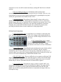
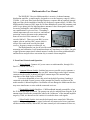
Multicontroller User Manual
The W8ZR H.F. Receiver Multicontroller is an active 8-channel antenna
distribution amplifier, or multicoupler, designed to cover the frequency range 0.1 MHz –
55 MHz. A low-pass filter limits the high-frequency response and an (optional) internal
high-pass filter can be installed to limit the low-frequency response below 1.8 MHz. The
Multicontroller features a BNC input for 50 Ohm unbalanced (coaxial fed) antennas, and
an RCA-type phono jack for high-impedance antennas. It has a front-panel-selectable
low-noise preamplifier, and capability for muting
any combination of seven receivers. Grounding a
control input mutes all seven receivers, and internal
protection circuitry disconnects the antenna and
mutes all receivers if the external r.f. voltage
exceeds 1000 mV. There are seven BNC receiver
outputs, plus an auxiliary BNC output which is
always active and can be used for an eighth
receiver, frequency counter, oscilloscope, etc.
The Multicontroller can also be used for testing, production, and frequency
measuring and calibration. It will transform almost any impedance to 50 Ohms, can split
a signal generator output into 8 isolated outputs. It makes an excellent wideband buffer
and line driver and provides a convenient way to control a linear amplifier.
I. Front Panel Controls and Operation
1. Power Switch: Connects AC power source to multicontroller, through 1/4A
fuse F1 (1/8A for 230 VAC).
2. Antenna Selector Switch: Switches between two possible receive antennas: a
50 Ω coax-fed antenna connected to the rear BNC antenna input, and a high-Z antenna,
connected to the rear RCA phono jack high-Z antenna input. The nominal input
impedance of the High-Z port is 1000 Ω.
It is not recommended to leave this switch in the high-Z position if nothing is
connected to the high-Z input, because of the potential for parasitic oscillation of the
multicontroller’s internal amplifiers. Oscillation will not damage the Multicontroller but
may cause interference or noise with the connected receivers.
3. Preamplifier Switch: Enables a +12dB broadband internal preamplifier, when
the 50 Ω antenna input is selected. The preamp can only be enabled when using the 50 Ω
antenna input. Because the preamplifier reduces the “headroom” of the internal amplifier
stages by 12 db, it is best not to use it unless it is needed to hear weak signals.
4. Mute Enable Switch: Activates the back-panel mute control jack. When the
switch is ON, grounding the mute control jack mutes all connected receivers (and turns
off their associated LEDs). When OFF, the mute control jack is disconnected. However,
2
connected receivers can still be muted manually by turning OFF their Receiver Enable
switches.
5. Receiver Enable Switches (7): Individually enable (unmute) their
corresponding receivers. When OFF, the associated receiver is muted. However, even
when enabled, all receivers can be muted simultaneously by grounding the rear-panel
control jack (provided the Mute Enable Switch is ON).
6. Overload Indicator: This indicator lights when RF voltage on the receive
antenna exceeds about 1000 mV. When lighted, all enabled receivers are muted and
antenna outputs RX1-RX7 are disabled. (The Aux Output always remains active.) Note
that the overload threshold is reduced by 12 db when the preamplifier is turned on.
Normally, the overload LED will flicker before the overload relay actuates, thus
providing an indication that overload conditions are being approached.
II. Rear Panel Connections
1. 50 Ω Antenna BNC Jack: A coaxial fed receive antenna is connected to this
jack. The input impedance is a resistive 50 Ω. DC voltages on the antenna should not
exceed 50V and RF voltages should not exceed
3.5 Vrms.
2. Hi-Z Antenna Phono Jack: A single
wire antenna is connected to this jack, which has a
nominal 1000 Ω input impednace. Voltage
precautions are the same as for the 50 Ω antenna.
3. Control Phono Jack: Grounding this jack simultaneously mutes all the enabled
receivers, provided the Mute Enable switch is ON. Normally, the jack would be
controlled by the PTT line or Relay line of the operator’s transmitter or transceiver. If
external control is not used, then a shorting plug should be placed in the jack to allow all
receivers to be muted simultaneously with the Mute Enable switch.
4. RX1-RX7 BNC Jacks: These are buffered receiver outputs, each having 50 Ω
output impedance. These duplicate the signal that appears at either of the antenna input
jacks. Note that these outputs are active even when the connected receivers are muted,
but that they are inactive (disconnected) if the Overload LED is lighted.
5. Aux Out BNC jack: This buffered output is similar to the RX1-RX7 ports,
except that it remains active even if the Overload LED is lighted. This output may be
slightly more susceptible to strong signal intermodulation distortion than the other
outputs, because back-to-back protective diodes are connected to the input of the Aux
Out amplifier stage.
3
6. RX1 – RX7 Phono Jacks: These are mute output jacks. The black jacks (RX4RX7) are normally closed and open when the connected receiver is muted. The red jacks
(RX1-RX3) are normally open and close when the connected receiver is muted. Voltage
and current limitations of the jacks (see Specifications) should be observed.
7. AC Power Connector: 115 VAC or 230 VAC is connected here, using an
ordinary IEC computer-type power cord. The Multicontroller is internally fused, and the
user is responsible for verifying that the appropriate fuse (1/4A for 115 VAC or 1/8A for
230 VAC is used.) Note that 230 VAC operation is only possible if a dual primary power
transformer (Stancor DSW-520) was installed during assembly.
III. General Instructions and Precautions:
1. Up to eight receivers may be connected to the multicontroller, although only seven of
them may be muted. BNC cables having a nominal 50 Ω impedance should be connected
from ports RX1-RX7 or the Aux Out port to the antenna inputs on the receivers. If the
connected receiver’s antenna input has 50 Ω impedance, then the signal from the
multicontroller will have the same strength as the signal appearing on the receive antenna
(gain of 0 dB).
Receivers of the vacuum tube era, or inexpensive modern receivers, may have
screw-type antenna terminals whose impedance is greater than 50 Ω. If this is the case,
signals from the multicontroller may appear up to 6 dB stronger (voltage gain of x2) than
the signals on the antenna, depending on the receiver’s actual input impedance.
2. Ordinary shielded phono cables should be connected from the seven mute output jacks
(under the RX1-RX7 BNC connectors) to the mute inputs of the connected receivers. The
black phono jacks (RX4-RX7) are normally-closed outputs, which open when the
receiver is muted. This open-to-mute convention is the most common and is used for
Drake, Collins, Hallicrafters and most other receivers of the vacuum tube era. Military
receivers (such as the R-390 and R-390A) and so-called “premium receivers” made by
Racal, Watkins-Johnson, Harris, and others typically use a close-to-mute convention and
should be connected to the red phono jacks (RX1-RX3). The user can reconfigure any of
the mute jacks as close-to-mute or open-to-mute by changing jumpers on the main circuit
board. Information about any receiver’s mute requirements can be found in the receiver’s
instruction manual.
Note that some receivers made in the 1950s and earlier have a front panel
“Standby Switch” which is in parallel with rear screw terminals. These terminals are
intended to be opened by contacts on an external antenna relay (such as a Dow Key relay)
in order to provide muting capability. In some designs, the Standby Switch (and external
contacts) simply disconnect plate voltage from the receiver’s tubes. The multicontroller
cannot be used to mute such receivers, both because the plate voltage is too high for the
multicontroller relay contacts, and because the multicontroller always grounds (or
ungrounds) the mute line, which would short to ground the recieiver plate voltage. For
such receivers, users should use an external relay to mute the receiver, with the
multicontroller controlling the external relay’s coil.
4
IV. Specifications:
Amplifier Circuits
1. Frequency Range:
50 Ohm input:
0.1 MHz – 55 MHz
1.8 MHz – 55 MHz
Hi – Z input:
0.1 MHz – 55 MHz
LF filter not installed
LF filter installed
2. Voltage Gain (nominal, per channel):
1.0 (0 dB)
50 Ω load, preamp off
2.0 (6 dB)
no load, preamp off
There is a broad 3 dB peak in the response from 40-60 MHz.
3. Typical 3 dB Bandwidth:
0.025 MHz – 72 MHz
1.8MHz – 72 MHz
50 Ω load, preamp off, LF filter not installed
50 Ω load, preamp off, LF filter installed
4. Antenna Input (50 Ω ) :
Impedance:
Clipping threshold:
Connector:
50 Ω nominal, d.c. blocked
1300 mV (+18 dBm), preamp off
BNC
5. Antenna Input (high-Z)
Impedance:
Clipping threshold:
Connector:
1000 Ω nominal, d.c. blocked
1500 mV, preamp off
RCA-type phono
6. Outputs (each channel):
Impedance:
Connector:
50 Ω nominal, d.c. blocked
BNC
7. Preamplifier:
+12 dB (nominal)
8. Internal Noise:
V < 0.2 µV
V < 30 µV
50 Ω input only
1 kHZ bandwidth @ 10 MHz
broadband 1.8 – 30 MHz
5
9. Absolute Maximum Input Voltage:
Maximum D.C. voltage :
Maximum RF voltage
±50 V
3.5 V(rms)
10. Overload Trip Threshold:
1000 mV(rms) nominal
50 Ω and high-Z inputs
Mute and Control Circuits
11. Mute Specifications:
Independent mute outputs:
Configuration:
Connector:
7
open-to-mute or close-to-mute, common ground
RCA-type phono
12. Mute Relay Ratings:
max. switched current:
max. switched voltage:
1 A, derate as switched voltage increases
125 VDC (25 mA), 150 VAC (100mA)
13. Control Input (ground to activate):
Open-circuit voltage:
Short-circuit current:
resistance to mute:
+12V
1.2 mA
<2.2 kΩ
General Specifications
14. Power Requirements:
90-130 VAC or 180-260VAC
15 Watts (nominal)
fuse: 1/4A 3AG (115V) or 1/8A 3AG (230V)
15. Dimensions:
Height: 3.5” (excluding feet)
Width: 7.2”
Depth: 6.00”
16. Weight:
5 lbs (2.27 kg)