1
MC-140i Multifunction Calibrator
2
Powertek
Operation Manual v33
Powertek
MC-140i Multifunction Calibrator
Content
Operation Manual ..................................................................................................................... 1
Basic Information ...................................................................................................................... 5
Preparation for operation .......................................................................................................... 6
Inspecting package contents, selecting the installation location ....................................................6
Power-on..............................................................................................................................................6
Warm-up time.....................................................................................................................................6
Replacement of fuse ...........................................................................................................................6
Safety precautions ..............................................................................................................................7
Description of controls .............................................................................................................. 8
Front panel ..........................................................................................................................................8
Rear panel .........................................................................................................................................12
Control of the calibrator .......................................................................................................... 13
Selection of function .........................................................................................................................13
Setting the value of output signal ....................................................................................................13
Setting relative deviation .................................................................................................................14
Change of value by factor of ten .....................................................................................................15
Connection / disconnection of output terminals ............................................................................16
Setting the frequency........................................................................................................................16
Generation of calibrated voltage .....................................................................................................17
Generation of calibrated current ....................................................................................................19
Simulation of temperature sensors .................................................................................................20
Setup menu .............................................................................................................................. 22
Calibration mode ..................................................................................................................... 26
Error messages ........................................................................................................................ 33
Functional description of the calibrator ................................................................................. 36
Calibrator’s maintenance ........................................................................................................ 41
Verification test ........................................................................................................................ 43
System control .......................................................................................................................... 48
RS232 bus properties .......................................................................................................................48
Command syntax ..............................................................................................................................48
Examples of use ....................................................................................................................... 54
Calibration of measurement instruments ......................................................................................54
Multimeters.................................................................................................................................................... 54
Thermometers ................................................................................................................................................ 55
Specification............................................................................................................................. 56
Accessories ............................................................................................................................... 59
Operation Manual v33
3
MC140i Multifunction Calibrator
4
Powertek
Operation Manual v33
Powertek
MC140i Multifunction Calibrator
Basic Information
MC-140i is a multifunction calibrator, to be used primarily as a standard for calibration laboratories. It
can be used for calibration of any measuring instrument which measures voltage, and current. The calibrator
includes a function which simulates thermocouple temperature sensors.
Basic features of the calibrator include: generation of calibrated DC and AC voltage in the range of 0
µV to 1000 V, DC and AC current in the range of 0 µA to 20 A (50 µA to 1000 A when using a 50-turn coil).
Maximum precision of the calibrator is 0.0035 % for DC voltage, 0.03 % for AC voltage, 0.013 % for DC
current and 0.055 % for AC current. Maximum frequency range is 20 Hz to 100 kHz.
Simulation of thermocouple temperature sensors can be used to calibrate thermometers and heat sensing
units. The calibrator allows the simulation of all common R, S, B, J, T, E, K, N type of thermocouples.
Compensation of cold junction of thermocouple is achieved by entering the respective temperature using the
calibrator’s keyboard. The accuracy of simulated temperature sensors depends on the value and type of sensor
and ranges from 0.4 oC to 4.3 oC.
The calibrator includes many other features which facilitate easy use. For example relative deviation
from set value of the output, currently displayed uncertainty of the output signal, calibration and internal testing
procedures. The concept of calibrator control and indication of its status is based on flat luminiscent display,
which provides all necessary information. The calibrator is controlled by opening menus on the display and
selection from menus. Frequently used functions are assigned direct-control keys. The calibrator comes with RS232 serial line, which allow the calibrator to be controlled from a PC.
The calibrator can easily fit within calibration systems featuring CALIBER/WinQbase software support.
ATTENTION !
The calibrator generates life-threatening high voltage.
The calibrator can only be used in line with this
Manual.
Operation Manual v33
5
MC-140i Multifunction Calibrator
Powertek
Preparation for operation
Inspecting package contents, selecting the installation location
Basic package includes the following items:
•
Multifunction calibrator
•
Power cord
•
Spare fuse T4L250/T, T8L250/T
•
Operation manual.
•
Test report
•
Test cable 1000V/20 A 2 pcs
•
RS 232 cable
The calibrator should be powered by 230/115 V – 50/60 Hz mains. It is a laboratory instrument whose
parameters are guaranteed at 23±2 oC. Before powering on the instruments, place it on a level surface. Do not
cover the vents at the bottom side and the fan opening at the rear panel.
Power-on
•
Before connecting the calibrator to the mains, check the position of the mains voltage selector located at the
rear panel.
•
Plug one end of the power cord into the connector located at the rear panel and connect the other end of the
power cord into a wall outlet.
•
Switch on the mains switch located at the rear panel. Flat display is lit.
•
The calibrator performs internal hardware checks for 5 seconds.
•
After the tests conclude, the calibrator resets to its reference state, i.e. the following parameters are set:
Function
DC voltage
Range
20 V
Set value
10 V
Output terminals
OFF
Note. The calibrator resets to its reference status in case of power switching off and reconnection.
Warm-up time
The calibrator works after it is switched on and the initial checks complete. Specified parameters are only
guaranteed after the instrument warms up for 60 minutes. During this period, the instrument cannot be calibrated.
The display shows “cannot access the calibration” message if calibration is attempted during this period.
Replacement of fuse
The calibrator includes a fuse located in the mains connector at the rear panel. Replace the fuse as follows:
•
Switch off the calibrator
•
Remove the end of power cord from the mains connector at the rear panel.
•
Insert the blade of a flat screwdriver into the opening cut in the mains voltage selector and pull out the fuse
holder.
•
Remove the fuse and replace it with new fuse of the same rating.
6
Operation Manual v33
Powertek
MC-140i Multifunction Calibrator
Safety precautions
The instrument has been designed in Safety Class I according to EN 61010-1. The design reflects the
requirements of A2 amendment of the standard.
Safety is ensured by the design and by the use of specific component types.
The manufacturer is not liable for the damage caused by modification of the construction or replacement of parts
with non-original ones.
Safety symbols used on the equipment
Warning, reference to the documentation
Warning - risk of electric shock
Danger - high voltage
Operation Manual v33
7
Powertek
4
MC-140i Multifunction Calibrator
Function buttons
Function buttons can be used to call-up the functions of the calibrator directly. The following buttons are
provided:
function
button
DC voltage
AC voltage
DC current
AC current
simulation of temperature sensors
U / DC
U / AC
I / DC
I / AC
T
After the function mode is changed, the parameters of the respective function are restored. If the respective
function was never used, the calibrator resets to its reference values. Reference values for individual functions are
listed below.
5
function
value
parameters
DC voltage
AC voltage
DC current
AC current
simulation of temperature sensors
cold junction temperature of TC sensors
10V
10 V
100 mA
100 mA
100 oC
23 oC
-f = 1000 Hz
-f = 1000 Hz
TC type R
Type R
Output terminal button
OUTPUT button is used to connect the output signal of the calibrator to the output terminals. The connection is
confirmed by symbol on the display.
6
Output terminals
Output signal of the calibrator is connected to the output terminals. Current ranges are connected to +I / -I
terminals. All other functions (voltage, temperature sensor simulation) are connected to Hi / Lo terminals.
GND terminal is connected to the chassis of the calibrator. It is connected to the ground terminal of the mains
plug. Using the SETUP MENU of the calibrator, the output terminals of the calibrator can be grounded as well.
Grounding is done internally by connecting Lo and GND terminals using a relay. This circuit design is suitable
for most calibrations, when the object (multimeter) being calibrated is floating.
Front panel display shows all information provided by the calibrator, e.g. set parameters of the signal, error
messages, setup information. The display is divided to several information sections.
Operation Manual v33
9
MC-140i Multifunction Calibrator
Powertek
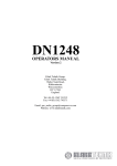
Display
7
1a 1b 1c 1d 1e
3
2b 1g 1f
The display is divided to three horizontal sections:
1.
OUTPUT section
This section displays the set-up values of generated signals and the data related to the calibrator status. The
section includes the following types of data:
a)
Information line
•
•
•
designation of display section: OUTPUT
error messages. The messages appear when an attempt is made to set up an invalid state of the
calibrator, if analogue circuits of the calibrator are overloaded or if a communication error occurs
when the calibrator is controlled using GPIB bus.
real date and time, if its display is set-up in the setup menu.
b) Auxiliary data
This line displays the total value of output signal if a non-zero relative deviation is set.
c)
Main data
This line displays the main data of the output signal and the unit of measurement (using double size
signs). The line also includes two symbols (▼▲) to define the actual position of the cursor during
adjustment of the value. <, > buttons can be used to move the cursor and ∧, ∨ buttons to change the
value. (The value can be also changed using the potentiometer).
d) Monitoring line
This line displays the numbers entered using the numeric keyboard when the main data are set using the
numeric keyboard. The information allows the entered information to be checked.
e)
Minor data
There are two lines displaying the minor data of the output signal, especially:
•
10
set relative deviation from main set value in %
Operation Manual v33
Powertek .
•
•
f)
MC-140i Multifunction Calibrator
frequency (for DC voltage, current, power, energy functions)
cold junction temperature of TC sensors and the selected type of TC sensor
Information section
The information section located in the right part of the display displays additional information related to
the selected function:
• symbol of connected
or disconnected
output terminals.
•
•
•
•
At the same time, a LED located above the OUTPUT button is lit.
information about remote/local control of the calibrator. If the calibrator is controlled remotely,
REM is displayed. If the calibrator is controlled locally using the keyboard, LOCAL is displayed.
information about the use of 50-turn coil (COIL x50) at the current output of the calibrator, if this
feature is turned on using the SETUP menu.
information about the type of connected cable adapter, if used
information about the grounding method of output terminals: GND I, GND U as set up using the
setup menu.
g) Information about the uncertainty of the output signal
This section displays the maximum error of the main value of the output signal. The value is calculated
using the main specification listed in the User’s Manual and it is displayed in %.
2.
INPUT section
This section displays the values measured by the multimeter. It is not available in MC-140i version.
3.
Display buttons section
This line displays the symbolic descriptions which define the meaning of four related display buttons. The
respective meanings are as follows:
symbol
button function
x 10
increase set value 10 x
: 10
decrease set value 10 x
+/-
reversed polarity of output voltage and current
Calib.
enter the calibration menu
SETUP
enter the setup menu
TC type
selection of thermocouple sensor type
only for T function
f
enter the frequency of the signal
only for U, I function
Operation Manual v33
note
only for DC U, DC I functions
11
MC-140i Multifunction Calibrator
Powertek
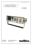
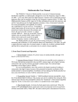
Rear panel
The rear panel of the calibrator includes ventilation holes, power cord socket with fuse, mains voltage selector,
mains switch, IEEE 488 connectors for connection to GPIB bus and type plate with serial number.
5
4
1
2
3
4
5
1
2
3
air inlet - forced ventilation
air outlet - forced ventilation
RS-232 connector
power cord socket with fuse, mains voltage selector, mains switch
type plate
12
Operation Manual v33
Powertek
MC-140i Multifunction Calibrator
Control of the calibrator
Selection of function
After the power is switched on and the initial checks complete, the calibrator resets to its reference status, i.e. DC
voltage output with set value of 10 V and output terminals disconnected. The status of the calibrator can be
changed using the buttons located at the front panel in one of the following ways:
1.
Change of function by pressing one of direct function buttons
After pressing one of the U, I, DC-AC, T buttons, the calibrator switches to the desired function mode and resets
to the reference or to the most recently used parameter setting.
2.
Connection /disconnection of output terminals
After pressing the OUTPUT button, the output terminals of the calibrator are connected/disconnected.
3.
Entry to the setup menu
After pressing the SETUP button, options of the SETUP MENU appear on the display and the display buttons
allow the entry to the calibration mode (CALIB). Previous function is restored by pressing of EXIT display
button.
Setting the value of output signal
All function modes allow several methods of setting the main value of the output signal:
Entry of the value using numeric keyboard
•
use the numeric keyboard to select the desired value. After the first digit is entered, symbols of unit
of measurements are displayed above the display buttons. The monitor line displays the symbols
[ _ _ _ _ _ _ _ _ ].
•
the same entry can be started by pressing the central cursor button
•
after the entry is complete (the value is displayed on the monitor line), press the display button
below the desired unit of measurement (V, mV or µV in the example below)
•
the value is copied to the main display and the monitor line disappears.
Operation Manual v33
13
MC-140i Multifunction Calibrator
Powertek .
Entry of the value using cursor buttons
•
press <, >, ∧ or ∨ button. The display now includes cursor marks which point to the active digit.
•
∧ and ∨ buttons can be used to change the active digit. <, > buttons can be used to change the
position of the cursor marks
•
to get to the default screen, press EXIT button or keep pressing the center cursor button until there
is no [ _ _ _ _ _ _ _ ] under any value. All values can be set using the buttons or the potentiometer.
Reverse polarity
In DC voltage and DC current modes, the polarity of the output value can be reversed by pressing +/- display
button. „ - “ symbol appears in front of the main data value.
Setting relative deviation
All function modes of the calibrator except frequency mode allow a relative deviation of output value from the
main data to be set using a separate display. Relative deviation is displayed in the “minor data” section of the
display and is designated with „ ∆%= 00.0000 % “ symbol. The relative deviation can be entered using one of the
methods described above, e.g. using the numeric keyboard, cursor keys or the potentiometer.
Setting relative deviation using numeric keyboard
14
•
keep pressing the center cursor button until [ _ _ _ _ _ _ _ ] symbols appear under the relative
deviation value in the “minor data” section of the display
•
enter the desired deviation and confirm the value by pressing “ % “ display button or by pressing
ENTER on the numeric keyboard
•
the auxiliary line below the main data on the display displays the total value of output signal
including the unit of measurement
•
the value of the signal at output terminals is:
the value indicated by the main display + ∆ %.
Operation Manual v33
Powertek
MC-140i Multifunction Calibrator
Maximum relative deviation which can be entered is ± 30.000 %.
The deviation can be positive or negative. If negative deviation is desired, press the display button labeled +/-. If
positive deviation is then desired, press “ +/- “ button again. The polarity of the relative deviation can be reversed
using the cursor buttons or the potentiometer as well.
Setting relative deviation using cursor keys
•
keep pressing the center cursor button until [
deviation value
•
press <, >, ∧ or ∨ button. The display now includes cursor marks which point to the active digit
•
∧ and ∨ buttons can be used to change the active digit. <, > buttons can be used to change the
position of the cursor marks
•
to get to the default screen, keep pressing the center cursor button until there is no [ _ _ _ _ _ _ _ ]
under any value, or press EXIT button. All values can be set using the buttons or the potentiometer.
_ _ _ _ _ _ _ ] symbols appear under the relative
If a non-zero relative deviation is set, the main data can be changed as well. The value of the output signal is
always recalculated. If a zero relative deviation is set, the “minor data” section is not displayed.
Change of value by factor of ten
All functions of the calibrator allow the increase of the output value by 10 or reduction of the output value by 10.
Such operation is equivalent to the change of internal range only in U, I modes. If the change results in overflow
or underflow of calibrator’s range, an error message appears:
Value too large !
if the resulting value is too large
Value too small !
if the resulting value is too small
Operation Manual v33
15
MC-140i Multifunction Calibrator
Powertek
Connection / disconnection of output terminals
After switching on the output terminals are disconnected in all modes. Press the OUTPUT button to connect the
output signal to the terminals. Information field on the display shows the following symbol
.
Press the OUTPUT button again to disconnect the output terminals. Information field on the display shows the
following symbol
.
During mode change, output terminals are always disconnected. Output terminals are disconnected also when
changing between voltage and current ranges or when changing between AC and DC ranges is performed.
If voltage over 100 V is set in the voltage mode, special algorithm must be followed to connect the output
terminals. The algorithm is described in the „Generation of calibrated voltage“ chapter of this Manual.
Setting the frequency
Frequency can only be selected in AC voltage (ACU) mode, AC current (ACI) mode. Set value of frequency is
included in the “minor data” section of the display.
Frequency change
•
First select the AC voltage or AC current mode by pressing U (I), AC buttons or selecting the P-E
mode using the display. Frequency value „f = xxx.xx Hz“ appears in the “minor data” section of the
display. “ f “ symbol is displayed above one of the display buttons.
•
After “ f “ display button is pressed, [ _ _ _ _ _ _ _ ] symbols appear below the frequency value.
Numeric keyboard can be used to enter the desired value. Press “ Hz “ or “ kHz “ to confirm the
value. The value can be set using the buttons or the potentiometer.
If too large or too small value is entered, the calibrator displays the maximum (minimum) value which is allowed
for the selected function.
16
Operation Manual v33
Powertek
MC-140i Multifunction Calibrator
Generation of calibrated voltage
The multifunction calibrator provides calibrated DC and AC voltage. Output terminals for voltage ranges are
labeled “ Hi “ and “ Lo “ at the front panel. Depending on the setting of the calibrator, voltage up to 1000 Vef
can be present at the terminals .
DC voltage range is 0 to 1000 V.
AC voltage range is 100 µV to 1000 V.
Control in the voltage mode
•
Press “U” button on the calibrator and then select AC or DC mode by pressing “DC-AC” button. The display
shows the following data:
*
*
*
*
*
main data of set voltage
relative deviation
uncertainty of output voltage
frequency (when AC voltage is generated)
total value of output voltage when non-zero relative deviation is set
•
Set the desired value of voltage, including polarity when necessary, frequency and relative deviation. The
signal is yet not connected to the output terminals. The information section of the display shows the symbol
which informs about the disconnection of output terminals.
•
Press OUTPUT button.
•
Information section of the display shows the symbol
•
Calibrated voltage corresponding to set parameters is present at the output terminals.
.
Control sequence when output voltage over 100 V is selected
When output voltage over 100 V is selected, the information section of the display shows the symbol
which
informs that a life-threatening voltage will be present at the output terminals. If the output terminals are currently
connected, they will be disconnected when output voltage over 100 V is selected. OUTPUT button must be
pressed to reconnect the output signal to the output terminals. After the OUTPUT button is pressed, an
interrupted beep is sound, information section of the display shows the symbol notifying the user about the
connection of the dangerous output signal to the output terminals.
Voltage, polarity, frequency, absolute and relative deviation can be set without the outputs being disconnected.
The output terminals are automatically disconnected when changing between AC and DC ranges or when
changing the function mode.
Overloading of terminals
If the output terminals are overloaded or short-circuited in the voltage mode, the calibrator disconnects the signal
from the output terminals and reports „Overload U output“ error.
Operation Manual v33
17
MC-140i Multifunction Calibrator
Powertek.
ATTENTION DANGEROUS VOLTAGE
When working with voltages over 50 V, rules for work with dangerous
voltage must be adhered to.
Never touch the measurement circuit when voltage over 50 V is set and
output terminals are connected!
ATTENTION
DANGEROUS VOLTAGE
When the calibrator is controlled remotely, it is not possible to disconnect
the output voltage using the buttons located at the front panel!
The calibrator must be first switched to local control mode by pressing the
LOCAL button and then the output terminals can be disconnected or the
mains switch must be switched off !
18
Operation Manual v33
Powertek
MC-140i Multifunction Calibrator
Generation of calibrated current
The multifunction calibrator provides calibrated DC and AC current. Output terminals for voltage ranges are
labeled “ +I “ and “ -I “ at the front panel. The terminals can carry high current and are the only terminals to
which the calibrated object can be connected. Depending on the setting of the calibrator, current up to 20 Aef can
be driven by the terminals.
DC current range is 0 to 20 A
AC current range is 1µA to 20 A
When 50-turn coil (option 140-50) is used, AC current range is 50µA to 1000 A.
Control in the current mode
•
Press “I” button on the calibrator and then select AC or DC mode by pressing “DC-AC” button. The display
shows the following data:
*
*
*
*
*
*
main data of set current
relative deviation
uncertainty of output current
frequency (when AC current is generated)
total value of output current when non-zero absolute or relative deviation is set
time after which the output terminals will be disconnected when the output current over 10 A is selected.
•
Set the desired value of voltage, including polarity when necessary, frequency and relative deviation. The
signal is yet not connected to the output terminals. The information section of the display shows the
symbol which informs about the disconnection of output terminals.
•
Connect the load or short the output terminals labeled +I, -I.
•
Press OUTPUT button.
•
Information section of the display shows the symbol
•
Calibrated current corresponding to set parameters is driven by the output terminals.
•
If COILx50 function is activated (see below - Setup functions menu), the optional 50-turn coil must be
connected to output terminals. The calibrator can be used to calibrate 50 µA to 1000 A ammeters. The
calibrator generates AC and DC current within the range up to 20 A.
.
CAUTION
If GND terminal is connected to Lo, -I terminals, it is prohibited to connect
external load to GND / Hi or GND / +I terminals. Such connection can
damage the calibrator.
Operation Manual v33
19
MC-140i Multifunction Calibrator
Powertek.
Overloading the terminals
When external circuit connected to current output terminals is disconnected or there is higher voltage at the lo ad
than permitted, the calibrator disconnects the output terminals and displays „Overload I output“ message. The
same message can be displayed when 50-turn coil is used for AC current output at frequencies above 80 Hz. It
depends on the set current and the type of ammeter connected.
If the output terminals are disconnected due to time limitation of output current over 10 A, the calibrator displays
„Current timeout !“ message.
Simulation of temperature sensors
The multifunction calibrator can simulate thermocouple temperature sensors. When thermocouples are simulated,
a simulated voltage corresponding to set temperature, sensor type and temperature of cold end of thermocouple is
connected to Hi - Lo terminals.
Temperature setting range:
Sensor types:
Temperature scale:
-250 to +1820 oC depending on simulated sensor type
thermocouple K, N, R, S, B, J, T, E
ITS 90, PTS 68
Setting the temperature
•
Press T button on the calibrator. The main value on the display is set temperature.
•
The display shows the following data:
*
*
*
*
main data of temperature in oC or K
sensor type
thermocouples:
K, N, R, S, B, J, T, E
cold junction temperature of thermocouple sensors labeled RJ
set value of relate deviation in %, labeled ∆T = xxxx.x °C (K)
the information section shows:
*
*
temperature scale type
uncertainty of simulated temperature value of selected temperature sensor type
•
Set the main value of temperature using numeric keyboard, cursor buttons or potentiometer. Output terminals
are disconnected, the information section of the display shows the symbol
which shows that output
terminals are disconnected.
•
Connect the object to be calibrated to Hi - Lo terminals.
•
Press OUTPUT button.
20
Operation Manual v33
Powertek
•
MC-140i Multifunction Calibrator
The display shows the symbol of connected output terminals.
Note
•
Load of output terminals is limited similarly to corresponding voltage or current ranges.
Entry of cold junction temperature
For thermocouples, the temperature of cold junction can be entered. The entry is performed by setting the RJ
field in the auxiliary data section of the display.
•
Select the thermocouple mode and keep pressing the center cursor button until [ _ _ _ _ _ _ _ ]
symbols appear under the (RJ = xxxx.x oC) value, if oC unit of measurement is used, or under
(RJ = xxxx.x K) value, if K unit of measurement is used.
•
Set the value using numeric keyboard.
•
Confirm the value by pressing oC or K display button or by pressing ENTER.
Operation Manual v33
21
MC-140i Multifunction Calibrator
Powertek.
Setup menu
The multifunction calibrator allows some other, less frequently used parameters to be set. Setup menu is used to
set these parameters. Setup menu is opened by pressing SETUP display button. If output terminals are connected,
they will be disconnected and the following display appears:
Use ∧ or ∨ cursor button or the knob of the potentiometer to browse the menu options. Active option is always
inverted and when changed, the descriptions of display buttons change as well. Display buttons show how the
respective parameter can be set. Each parameter can be changed after the knob of the potentiometer is pressed.
Press EXIT display button twice to save the parameters when the setting is completed. New settings are retained
when the calibrator is switched off. Setup menu offers the following options:
1.
Coil x50 .... xx
ON/OFF
This parameter can be set on when 50-turn current coil is going to be used for clamp ammeter calibration. The
coil multiplies the output current. OFF is set by the manufacturer.
2.
GND U .... xx
ON/OFF
This parameter connects Lo terminal to GND. In practice this means that Lo terminal is grounded. By pressing
the display buttons, the terminal can be grounded or ungrounded. ON is set by the manufacturer, output terminal
is grounded.
3.
GND I .... xx
ON/OFF
This parameter connects -I to GND. In practice this means that -I terminal is grounded. By pressing the display
buttons, the terminal can be grounded or ungrounded. OFF is set by the manufacturer, output terminals are not
grounded.
It is recommended to ground only the voltage channel GND U ON, GND I OFF, for all ranges except the
generation of power or energy. If the meter to be calibrated has Lo terminal grounded, it is recommended to
unground both outputs of the calibrator, GND U OFF, GND I OFF to exclude ground loops.
Note
22
Operation Manual v33
Powertek
MC-140i Multifunction Calibrator
If neither the calibrator’s output, nor the meter’s inputs are grounded, signal/noise ratio can arise at the
calibrator’s output.
4.
Temp.scale .... xx
ITS90/PTS68
This parameter allows the temperature scale for platinum resistance temperature sensors to be selected. Pressing
the display buttons allows to switch between ITS90 and PTS68 temperature scales. ITS90 is set by the
manufacturer.
5.
Temp.unit .... xx
o
C/K
This parameter allows the temperature unit for simulation of temperature sensors to be selected. Pressing the
display buttons allows to switch between °C and K. °C is set by the manufacturer.
6.
Phase.unit .... xx
N/A
Not available in MC-140i version.
7.
Output 140-41 .... xx N/A
Not available in MC-140i version.
8.
Meter average .... xx N/A
Not available in MC-140i version.
9.
Interface .... xx
N/A
Not available in MC-140i version.
10. GPIB address .... xx N/A
Not available in MC-140i version.
11. RS232 baud rate .... xx
UP/DOWN
Indicates the communication speed of RS232 bus. UP/DOWN display buttons can be used to select 150, 300,
600, 1200, 2400, 4800, 9600, 19200. Perfect communication with the PC requires equal values set at the PC and
the calibrator.
12. Handshake .... xx
OFF/Xon-Xoff
Indicates the communication handshake. Display buttons can be used to select OFF or Xon/Xoff. Perfect
communication with the PC requires equal values set at the PC and the calibrator.
13. Keyb.beep .... xx
ON/OFF
This parameter allows the acoustic indication of pressed buttons to be switched off or on. ON and OFF display
buttons can be used to switch the indication off or on. ON is set by the manufacturer.
Operation Manual v33
23
MC-140i Multifunction Calibrator
Powertek.
This parameter does not control the acoustic indication of output voltages over 100 V and identification of errors.
14. Keyb.volume .... xx
UP/DOWN
This parameter allows the volume of acoustic indication to be set. UP and DOWN display buttons allow to set
the value in the range of 00 to 15. The bigger the value, the louder sound. This parameter controls the volume of
keyboard beep (if switched on), indication of output voltages over 100 V and identification of errors when
controlling the calibrator.
15. Brightness .... xx
UP/DOWN
This parameter sets the contrast of the display. UP and DOWN display buttons allow to set the value in the range
of 00 to 15.
16. Rotary change .... xx N/A
Not available in MC-140i version.
17. Switch polarity .... xx N/A
Not available in MC-140i version.
18. Switch activity .... xx N/A
Not available in MC-140i version.
19. Cal.code .... 00000
Entry of calibration code. Calibration code is a five-digit number, which must be entered to access the calibration
mode. If the calibration code is set to “00000”, this information is displayed in the Setup menu. Calibration code
can be changed. New calibration code can be directly entered using numeric keyboard and confirmed by pressing
ENTER. If non-zero calibration code is set, correct calibration code must be entered to access the calibration
mode. Non-zero calibration code is not displayed further on the display.
The purpose of the calibration code is to prevent unauthorized users from changing the calibration of the
instrument.
Note
24
Operation Manual v33
Powertek
MC-140i Multifunction Calibrator
It is advisable to write down actual calibration code if changed. If you forget the calibration code, you have to
send the calibrator to the manufacturer.
20. Cal.date .... xx.yyyy
Displays the date of last calibration of the calibrator (month/year). The parameter cannot be changed, as it is
automatically recorded when leaving the calibration mode.
21. Serial No .... xxxxxx
Displays the serial number of the calibrator. The parameter cannot be changed.
22. Time .... xx:yy
Displays real time. The parameter can be changed using HOUR UP, HOUR DO, MIN UP, MIN DO. display
buttons.
23. Date .... xx.yy.zzzz
Displays real time. The parameter can be changed using DAY UP, MONTH UP, YEAR UP, YEAR DO display
buttons.
24. Time on display .... xx
ON/OFF
If set to ON, time and date are displayed in the upper part of the display. If OFF is set, time and date are not
displayed. ON is set by the manufacturer.
Operation Manual v33
25
MC-140i Multifunction Calibrator
Powertek
Calibration mode
The multifunction calibrator includes a calibration procedure, which allows calibration of the calibrator. Zero
point and slope of the characteristics of individual generation and measurement ranges are set during the
calibration in predefined order. The calibration can only be controlled using the buttons and menu on the
calibrator.
Calibration principles
The calibrator can be calibrated:
•
•
•
completely, i.e. all functions are calibrated in all recommended points
partially, i.e. only selected functions are calibrated in all recommended points
partially, i.e. only selected functions are calibrated in selected points
Complete calibration consists of all partial calibrations performed in the order defined by the calibration menu. If
an item of the calibration menu, e.g. “VOLTAGE DC” is selected, it is not necessary to calibrate all ranges
defined by the calibration algorithm. If new calibration of all ranges is not possible (e.g. the required standard is
not available), old calibration data can be confirmed, i.e. current step of the calibration can be skipped.
Calibration interruption can be performed in any point of the calibration
procedure. However this particular calibration influences parameters of the
calibrator.
Accuracy of the calibrator is guaranteed when full calibration was done.
DC voltage calibration is performed by setting the zero and slope of the scale in all ranges and in both signal
polarities (+ and -) (except the 1000 V range, where zero correction is not necessary).
AC voltage calibration is performed by setting the zero and slope of the scale in all ranges at 1000 Hz (except
the 1000 V range, where the calibration is performed at 500 Hz).
DC current calibration is performed by setting the zero and slope of the scale in all ranges and in both signal
polarities (+ and -).
AC current calibration is performed by setting the zero and slope of the scale in all ranges at 1000 Hz (except
the 20 A, where the calibration is performed at 120 Hz).
Access to the calibration procedure
Calibration code is required to access the calibration procedure.
•
Press SETUP to open the setup menu.
•
Press CALIB display button.
•
If an attempt is made to access the calibration procedure within 60 minutes after the calibrator was switched
on, the calibrator does not open the respective menu and displays the following message instead:
Err 21
Time warm up !
xx minutes remain
26
Operation Manual v33
Powertek
MC-140i Multifunction Calibrator
•
If the calibrator is already on for at least 60 minutes, it requests the entry of the calibration code after CAL.
MODE display button is pressed.
•
Enter the correct calibration code using numeric keyboard and press ENTER.
•
If incorrect calibration code is entered, an error message appears on the display for approximately 3 seconds:
Err 20
Bad calib. code!
•
If correct calibration code is entered, calibration menu appears:
•
Use ∧ and ∨ cursor buttons to move the cursor through the list:
1.
2.
3.
4.
Note:
VOLTAGE DC
VOLTAGE AC
CURRENT DC
CURRENT AC
All DC voltage ranges calibration
All AC voltage ranges calibration
All DC current ranges calibration
All AC current ranges calibration
All the rest functions labeled as N/A are not available in MC-140i version.
Selection of calibration type
Operation Manual v33
27
MC-140i Multifunction Calibrator
Powertek
After the calibration menu is displayed, one of partial calibrations can be selected. Use ∧ and ∨ cursor buttons to
move the cursor through the list. Having selected the required function to be calibrated, press SELECT display
button. The following data are shown (the following example is valid for VOLTAGE DC range):
The table lists recommended calibration points. Having selected the required calibration point using SELECT
display button, the following data are shown.
Display buttons have the following meaning:
WRITE
new calibration value is entered into the memory, old value is irreversibly lost
SKIP
current calibration step is skipped, old value is retained in the memory
EXIT
current calibration is terminated. After this button is pressed, the calibration memory
hold all data (old or new entered) and the calibrator returns to the calibration
menu. It is not necessary to calibrate all ranges; calibration of only selected ranges
is possible by skipping the ranges which do not need to be calibrated.
Moreover, the display shows the range which is being calibrated (RANGE), and the value to be set at the external
standard multimeter (VALUE).
28
Operation Manual v33
Powertek
MC-140i Multifunction Calibrato
Setting the new calibration data
Use ∧, ∨, <, > cursor buttons to set such main data on the display, when the output signal measured by external
standard multimeter reaches the required calibration point. When the standard output value is reached, press
“WRITE” to write new calibration value to the calibration memory. If you press “SKIP” button, the calibrator
ignores the new value and old value is retained. After you press “WRITE” (or “SKIP”), the calibrator moves on
to the next calibration point.
The procedure is repeated for all calibration points of the selected function. If you press “EXIT” button before
completing the calibration, the calibrator returns to the calibration menu.
Termination of calibration
The calibration can be terminated in the following cases:
•
complete calibration has been performed, new calibration data have been entered, the program has returned
to the calibration menu,
•
calibration of selected function has been performed, new calibration data have been entered, the program has
returned to the calibration menu,
•
calibration of selected range(s) of selected function has been performed, new calibration data have been
entered, the program has returned to the calibration menu,
•
the calibration has been started but no calibration data have been entered, the program has returned to the
calibration menu after “EXIT” display button has been pressed,
Press “EXIT” display button to terminate the calibration. After the button is pressed, the calibration date is saved
internally and the calibrator returns to the state it was in before the calibration has been started.
Calibration points
Each function of the calibrator has assigned fixed calibration points which have to be set during the calibration.
For VOLTAGE DC, VOLTAGE AC, CURRENT DC, CURRENT AC the signal value is set using the keyboard.
T function does not require any calibration, as the output voltage or resistance is based on arithmetic
interpolation using standard tables of temperature sensor values.
The calibrator needs no calibration of the frequency parameter.
Operation Manual v33
29
MC-140i Multifunction Calibrator
Powertek
VOLTAGE DC function
nominal value [V]
0.0
0.0
19 m
-19 m
0.0
0.0
190 m
-190 m
0.0
0.0
1.9
-1.9
0.0
0.0
19
-19
0.0
0.0
190
-190
1000
-1000
Table DC VOLTAGE
set limits [V]
range [V]
note
2u
2u
4u
4u
2u
2u
6u
6u
5u
5u
12 u
12 u
20 u
20 u
100 u
100 u
200 u
200 u
600 u
600 u
20 m
20 m
20 m
-20 m
20 m
-20 m
200 m
-200m
200 m
-200m
2
-2
2
-2
20
-20
20
-20
200
-200
200
-200
1000
-1000
zero calibration
zero calibration
slope calibration
slope calibration
zero calibration
zero calibration
slope calibration
slope calibration
zero calibration
zero calibration
slope calibration
slope calibration
zero calibration
zero calibration
slope calibration
slope calibration
zero calibration
zero calibration
slope calibration
slope calibration
slope calibration
slope calibration
VOLTAGE AC function
nominal value [V]
1.9 m
19 m
19 m
190 m
190 m
1.9
1.9
19
19
190
190
750
Table AC VOLTAGE
set limits [V]
5u
10 u
15 u
40 u
30 u
100 u
200 u
1m
5m
10 m
50 m
50 m
range [V] recommended frequency[Hz]
20 m
20 m
200 m
200 m
2
2
20
20
200
200
1000
1000
1000
1000
1000
1000
1000
1000
1000
1000
1000
1000
1000
500
Other then recommended frequencies can be used for calibration. Specification of the calibrator is valid when
recommended frequency is used.
30
Operation Manual v33
Powertek
MC-140i Multifunction Calibrato
CURRENT DC function
nominal value [A]
0.0
0.0
190 u
190 u
0.0
0.0
1.9 m
1.9 m
0.0
0.0
19 m
-19m
0.0
0.0
190 m
-190 m
0.0
0.0
1.9
-1.9
0.0
0.0
10
-10
Table DC CURRENT
set limits [A]
range [A]
note
3n
3n
5n
5n
20 n
20 n
50 n
50 n
100 n
100 n
200 n
200 n
1u
1u
2u
2u
20 u
20 u
50 u
50 u
300 u
300 u
600 u
600 u
200 u
-200 u
200 u
-200 u
2m
-2 m
2m
-2 m
20 m
-20 m
20 m
-20 m
200 m
-200 m
200 m
-200 m
2
-2
2
-2
20
-20
20
-20
zero calibration
zero calibration
slope calibration
slope calibration
zero calibration
zero calibration
slope calibration
slope calibration
zero calibration
zero calibration
slope calibration
slope calibration
zero calibration
zero calibration
slope calibration
slope calibration
zero calibration
zero calibration
slope calibration
slope calibration
zero calibration
zero calibration
slope calibration
slope calibration
CURRENT AC function
nominal value [A]
19 u
190 u
190u
1.9 m
1.9 m
19 m
19 m
190 m
190 m
1.9
1.9
10
Table AC CURRENT
set limits [A]
5n
50 n
40 n
200 n
200 n
2u
2u
20 u
20 u
200 u
1m
3 m
range [A] recommended frequency[Hz]
200 u
200 u
2m
2m
20 m
20 m
200 m
200 m
2
2
20
20
1000
1000
1000
1000
1000
1000
1000
1000
500
500
120
120
Other then recommended frequency can be used for calibration. Specification of the calibrator is valid when
recommended frequency is used.
Operation Manual v33
31
MC-140i Multifunction Calibrator
Powertek
Full calibration procedure
Following pages describe procedure of the full calibration.
Required instruments:
Following instruments are required for calibration:
•
81/2 digit multimeter type Agilent 3458A or Fluke 8508A or other type with accuracy 0.001 % on DC
voltage
•
Resistance shunt 10 mΩ, 100 mΩ Burster 1280, or other type with accuracy 0.01%
•
Counter HP 53181A, HO 53130, BM 642 or other with accuracy 0,001 %
HP8903A Distortion analyzer and scope with bandwidth min. 20 MHz are recommended for THD measuring of
AC signals.
Calibration procedure
1.
Connect the calibrator and the multimeter to the mains and let them switched on for at least three hours
in a laboratory at 23±1 oC.
2.
Press SETUP display button to call up the setup menu and then CALIB display button to call up the
calibration menu.
3.
Enter the calibration code and press ENTER (default calibration code is “00000”).
4.
DC voltage ranges calibration
5.
32
a)
Connect the voltage input terminals of the multimeter to the Hi - Lo output terminals of the
calibrator.
b)
Select VOLTAGE DC from the calibration menu and confirm by pressing SELECT button.
Switch MC-140 output terminals ON.
c)
Follow the instructions provided on the calibrator’s display and the DCU table to adjust the
calibrator’s output in the calibration points.
d)
To adjust the calibrator’s output in the calibration points, press SELECT button and use <, >,
∨, ∧ cursor buttons or potentiometer to adjust output voltage. Confirm correctly set value by
pressing WRITE display button. If you want to skip the calibration point whose calibration you
have already entered, press SKIP display button.
e)
Switch output terminals OFF
AC voltage ranges calibration
a)
Select VOLTAGE AC from the calibration menu and confirm by pressing SELECT button.
Switch MC-140 output terminals ON.
b)
Follow the instructions provided on the calibrator’s display and the ACU table to adjust the
calibrator’s output in the calibration points.
c)
To adjust the calibrator’s output in the calibration points, press SELECT button and use <, >,
∨, ∧ cursor buttons or potentiometer to adjust the output voltage. Confirm correctly set value
by pressing WRITE display button. If you want to skip the calibration point whose calibration
you have already entered, press SKIP display button.
d)
Switch output terminals OFF. Disconnect multimeter and calibrator.
Operation Manual v33
Powertek
6.
7.
MC-140i Multifunction Calibrato
DC current ranges calibration
a)
Connect current input terminals of the multimeter to the +I - -I output terminals of the
calibrator. Select CURRENT DC from the calibration menu.
b)
Select DC current measurement range on external multimeter. Switch output terminals ON
c)
Follow the instructions provided on the calibrator’s display and the DCI table to adjust the
calibrator’s output in the calibration points.
d)
To adjust the calibrator’s output in the calibration points, press SELECT button and use <, >,
∨, ∧ cursor buttons or potentiometer to adjust the output current. Confirm correctly set value by
pressing WRITE display button. If you want to skip the calibration point whose calibration you
have already entered, press SKIP display button.
e)
Resistance shunt should be used on 2A, 20 A ranges, if standard multimeter does not cover this
range.
AC current ranges calibration
a)
Select CURRENT AC from the calibration menu. Set the same function on external
multimeter.
b)
Follow the instructions provided on the calibrator’s display and the ACI table to adjust the
calibrator’s output in the calibration points.
c)
To adjust the calibrator’s output in the calibration points, press SELECT button and use <, >,
∨, ∧ cursor buttons or potentiometer to adjust the output current. Confirm correctly set value by
pressing WRITE display button. If you want to skip the calibration point whose calibration you
have already entered, press SKIP display button.
d)
Resistance shunt should be used on 2A, 20 A ranges, if standard multimeter does not cover this
range.
Error messages
If an error occurs during the calibrator’s operation or control, error message is displayed on the display. Errors
can be caused by:
•
incorrect control using the front panel, i.e. attempts to force a prohibited mode, e.g. setting an out-of-range
value, overloading of output terminals etc.,
•
fault of the calibrator, e.g. internal communication error during the communication between individual
functional blocks,
•
incorrect control using RS-232 interface.
Below you can see a sample error message which appears when too large value is attempted to set up. All error
messages are displayed in the center of the display.
Operation Manual v33
33
MC-140i Multifunction Calibrator
Powertek
The following table lists all error messages, their meaning and simple troubleshooting.
34
Operation Manual v33
Powertek
No
error
MC-140i Multifunction Calibrato
label
description
troubleshooting
01
Overload 2V !
2V range overloaded
Output current is too high. Increase load resistance.
02
Overload 20V !
20 V range overloaded
Output current is too high. Increase load resistance.
03
Overload 200V !
200, 1000 V ranges
overloaded
Output current is too high. Increase load resistance.
04
Overload I output ! Current output overloaded
Voltage on the load is too high. Decrease load resistance.
05
High temperature !
Too high internal
temperature
Output stages are overloaded. Do not use ranges 200V, 1000V or
20 A for at least 10 minutes. Check if the ventilation holes are
free.
06
Overload RC !
RC simulator overloaded
Test current is too high. Use lower range of tested Ohmmeter.
07
FBK error !
Internal error
Turn off the calibrator and turn on it again.
08
OUTPUT must be
in OFF state !
Cable adapter tried to be
exchanged while output
terminals was ON
Switch off output terminals with button OUTPUT, change the
adapter, and switch output terminals on.
20
Bad calib. code !
Bad calibration code
Wrong calibration code was entered, calibration cannot start.
Enter correct calibration code.
21
Time warm up !
Attempt to start calibration
before warm up
Attempt to start calibration before 60 minutes warm up period.
Let the calibrator turned on for at least 60 minutes.
30
Internal RxD
timeout !
Internal error
Internal error of the calibrator. Turn the calibrator off and after 5
s turn on. If the error will appear again, contact manufacturer.
31
Internal
communication !
Internal error
Internal error of the calibrator. Turn the calibrator off and after 5
s turn on. If the error will appear again, contact manufacturer.
37
Calibrator is not
ready !
Internal error
Internal error of the calibrator. Turn the calibrator off and after 5
s turn on. If the error will appear again, contact manufacturer.
40
Value too large !
Maximum value is out of
limit
Attempt to set value over possible range. Set correct value.
41
Value too small !
Minimum value is out of
limit
Attempt to set value under possible range. Set correct value.
42
Deviation too large Deviation is too high
!
Set deviation is out of limit –30% to +30%. Set correct value.
44
Unable +/- !
Change of polarity is not
allowed
Attempt to change polarity, where it is not allowed.. Concerned
modes ACV, ACI.
45
Unable – polarity !
Negative polarity is not
allowed.
Attempt to set negative polarity, where it is not allowed..
Concerned modes ACV, ACI.
46
Unable DC/AC !
DC/AC conversion is not
possible
Attempt to change parameter AC/DC where it is nonsense or
where it is not allowed.
47
Current timeout
Time limit for current over
10 A exceeded
Long-term loading current terminals with output current over A.
!
Operation Manual v33
35
MC-140i Multifunction Calibrator
Powertek
Functional description of the calibrator
Basic blocks
Basic functional blocks are:
•
•
•
•
•
•
•
•
•
•
•
•
•
•
•
•
•
front panel keyboard
LCD display
output terminals
output voltage amplifier 200 V
output voltage amplifier 20 A
main board
voltage amplifier 2 V
voltage amplifier 20 V
DC reference voltage with DAC
generator
feedback circuits
phase shift circuits
current ranges generator
multimeter
power line transformer
power supply board
interface GPIB and RS232
Note:
36
List of basic functional blocks contains all blocks of MC-140 model. In MC-140i version some of them
miss.
Operation Manual v33
Powertek
Operation Manual v33
MC-140i Multifunction Calibrator
37
MC-140i Multifunction Calibrator
Powertek
2, 20 V DC voltage ranges
The functional scheme is shown in the picture below:
There is a DC reference voltage source integrated within the 22bit measurement converter. Its output is fed to the
output stage for 2 and 20 V range. Output voltage present at Hi and Lo terminals is sensed by sensing wires.
Feedback eliminates the influence of amplifier’s output impedance and of the resistance of wires within the
calibrator.
200 V DC voltage range
The block diagram functional scheme is shown in the picture below.
The scheme is similar to 2 and 20 V ranges. A 240 V power amplifier with electronic fuses is connected to the
output of 20 V amplifier.
2 to 200 V AC voltage ranges
The functional scheme is shown in the picture below:
38
Operation Manual v33
Powertek
MC-140i Multifunction Calibrator
The calibrator’s built-in generator generates a sine wave with voltage-controlled amplitude. The frequency is
derived from microprocessor control circuit’s crystal oscillator. The signal is fed to 20 V or 200 V amplifier and
then to output terminals. Feedback circuits sense the voltage present at the output terminals, normalize its value
and detects it. This results in a signal corresponding to average value of the output voltage. This signal is further
filtered and compared to the set value of output voltage. The error value controls the amplitude of the generator’s
output.
20mV and 200 mV voltage ranges
20 mV and 200 mV voltage ranges are derived from 2 and 20 V voltage ranges.
The output of the amplifier is fed to an inverting attentuator with 1:100 nominal division ratio. The signal is then
led to the output terminals, sensed via local feedback. This connection allows to load the calibrator output with
output current of several mA without losing accuracy.
1000 V AC, DC voltage range
The highest voltage range of the calibrator uses 200 V amplifier. It is connected to a pair of transformers with ca
1:6 transformation ratio.
In 1000 V AC mode, the output of 200 V amplifier is transformed and led to the output terminals. The output
voltage is sensed, rectified and compared to reference DC voltage provided by the DA converter. error value
controls the amplitude of the generator’s output so that there is correct voltage at the output terminals.
In 1000 V DC mode, 12 kHz signal is transformed, rectified, filtered and led to the output terminals. The output
voltage is sensed equally to 1000 V AC mode.
Operation Manual v33
39
MC-140i Multifunction Calibrator
Powertek
Current converter
The current converter and current amplifier form a separate design block based on a transconductivity converter
with 10-5 S nominal conversion ratio.
A six-range switched current amplifier connects to the output of the current converter. Its input is fitted with
overload
protection and a separate circuit which measures the shift between output voltage and current in 2 and
input
20 A current ranges. The output stage is push-pull in B class.
power stage
Resistance and capacitance simulator
Resistance and capacitance are simulated using an electronic simulator.
DA convertor
power stage
Hi and Lo are calibrator’s output terminals. The stage including U1 operating amplifier converts voltage to
current. U2 is a separation amplifier. R1 to R5 and C1 to C3 are range impedance. DA converter has 0 to +1 and
0 to -1 conversion ration and allows the simulation of resistance and capacitance values different from the range
impedances. The output stage increases the permitted current load of the output.
ATTENTION
The simulator’s output voltage (Hi - Lo terminals) is limited to 8 Vpk.
Frequency synthesizer
Frequency synthesis circuitry allows fine setting of frequency in the whole calibrator’s range. Frequency
synthesis uses DSP circuits with basic frequency 20 MHz.
40
Operation Manual v33
Powertek
MC-140i Multifunction Calibrator
Calibrator’s maintenance
The multifunction calibrator is electronic instrument with microprocessor control. All blocks which are heavily
loaded during the operation are cooled by a fan.
Rules for correct operation
Especially the following rules should be adhered to guarantee correct operation of the calibrator:
• The calibrator can only be switched on and off by pressing the mains switch located at the rear panel.
• Do not connect the calibrator to other voltage than set by the voltage selector.
• Do not block the vent openings located at the rear panel and bottom panel.
• The calibrator must not be operated in dusty environment. It was designed to be used in a laboratory.
• No liquid or small objects can be permitted to enter the calibrator through the vent openings..
• Do not switch the calibrator outside its operating temperature range.
• Connect the instruments to be calibrated to proper output terminals. There is no way of protecting the
calibrator from the damage caused by some improper connections.
• Do not damage the output terminals by plugging in “bananas” thicker than the terminals were designed
for.
• Whenever possible, use the setup menu to ground Lo output terminal (GND U ON setup function).
• Do not overload the power stages by leaving the calibrator switched on with the load connected for a long
time, especially on 20 A current range and 200V and 1000 V voltage ranges.
• If the instruments to be calibrated are not connected to calibrator’s output terminals using original cables,
ensure that cables suitable for the calibration voltage and current are used. Maximum output voltage can
reach 1000 V AC and the maximum output current can reach 20 A AC.
Regular maintenance
The calibrator does not require any special maintenance of electrical or mechanical parts. If is gets dirty, the case
and the display can be cleaned by a wool rag moistened with alcohol.
The calibrator should be calibrated in the recommended 12-month intervals. A calibration center should perform
the calibration.
What to do in case of failure
If an obvious failure occurs during the operation (e.g. the display is not lit, the fan is not turning), the calibrator
must be switched off immediately. First, check the fuse located in the power cord receptacle. Procedure is
following:
•
Remove the end of power cord from the mains connector at the rear panel.
•
Insert the blade of a flat screwdriver into the opening cut in the mains voltage selector and pry out the fuse
holder.
Operation Manual v33
41
MC-140i Multifunction Calibrator
• Remove the fuse. Replace it with new fuse of the same rating if the fuse was broken.
Powertek
• Replace the fuse holder, reconnect the power cord and switch on the calibrator. If the problem persists,
contact the manufacturer.
If an obvious fault is evidenced, e.g. a measurement range or an operating mode is not functional, the user cannot
correct the fault. Contact the manufacturer.
Hidden faults can cause different symptoms and be caused by different causes. Usually, they cause instability of
some parameter. Hidden defects can be caused by unacceptable distortion, degraded insulation etc. In this case
contact the manufacturer.
Sometimes it seems that the calibrator has hidden defect, when the rules for correct operation are not adhered to.
In this case, the fault is caused by the operator. Most frequent cases of false “hidden defects”:
• mains voltage out of tolerance limits or unstable
• wrong grounding of the measurement circuit (bad connection of the ground terminal of the mains outlet, or
several ground connection when grounding loops are formed)
• proximity to sources of intensive influence, whose products are spread through the mains or propagated by
the electromagnetic field
• strong electrostatic or electromagnetic field which can cause major instability during calibration using higher
impedance.
42
Operation Manual v33
Powertek
MC-140i Multifunction Calibrator
Verification test
Procedure recommended for verifying parameters of the calibrator is described in this chapter. During tests it is
not necessary access to the interior of the instrument.
Required equipment
Following instruments are required for performance verification test:
•
81/2 digit multimeter type Agilent 3458A or Fluke 8508A or other type with accuracy 0.001 % on DC
voltage
•
resistance shunt 10 mΩ, 100 mΩ Burster 1280, or other type with accuracy 0.01%
•
counter HP 53181A, HO 53130, BM 642 or other with accuracy 0,001 %
HP8903A Distortion analyzer and scope with bandwidth min. 20 MHz are recommended for THD measuring of
AC signals.
Configuration of the calibrator
Calibrator should be tested directly from the front panel terminals and without use of terminal adapter 140-01 or
140-41. For build-in multimeter testing cable adapters Option 40 and Option 60 are recommended. To suppress
influence of noise or interference with power line frequency in measuring circuit it is recommended following
setting of the calibrator (in SETUP MENU):
•
•
•
Coil x50
GND U
GND I
Note:
OFF
ON (in capacitance test OFF)
ON (in capacitance test OFF)
It is recommended to ground only the voltage channel GND U ON, GND I OFF, for all ranges
except the generation of power or energy. If the meter to be calibrated has Lo terminal
grounded, it is recommended to un-ground both outputs of the calibrator, GND U OFF, GND I
OFF to exclude ground loops.
If it is grounded neither calibrator nor standard meter, higher level can occur on the output
terminals.
In general, when calibrator is connected to the standard meter, ground loops can be arise
through power line connection. Ground loops can result apparently worse noise, short term
stability or non-harmonic distortion of output signal. If necessary use toroidal chokes to
suppress this products.
In all other items in SETUP MENU the setting of parameters don’t influence accuracy of the calibrator.
Use sin waveform of the output signal on all AC tests.
Performance verification may be performed after warm-up period i.e. 1 hour after switching on. Calibrator have
to be in temperature stabilize condition at minimum 8 hours before performance verification test is started.
Basic steps of the performance verification test
Verification procedure consists of following steps:
•
20 V DC voltage test with linearity check
Operation Manual v33
43
MC-140i Multifunction Calibrator
•
DC voltage internal ranges 20 mV, 200 mV, 2 V, 240 V, 1000 V test
•
20 V AC voltage test with linearity check
•
AC voltage internal ranges 20 mV, 200 mV, 2 V, 20V, 240 V, 1000 V test
•
200 mA DC current test with linearity check
•
DC current internal ranges 200 uA, 2 mA, 20 mA test
•
AC current internal ranges 200 uA, 2 mA, 20 mA, 200 mA test
•
AC/DC high current ranges 2 A, 20 A test
•
Frequency nominal value 1 kHz test
•
Distortion checking of AC voltage, range 20 V.
Powertek
Procedure
Following part describes procedure of performance verification test. Recommended measuring points are the
same as the points in table of limits (see tables bellow).
1.
Connect the calibrator to the mains and let them switched on for at least one hour in a laboratory at 23±1 oC.
2.
Connect voltage input of the standard multimeter to the voltage output terminals of the calibrator. Set
appropriate parameters on the standard multimeter to achieve its best accuracy.
3.
Perform 20 VDC linearity, DC voltage, 20 VAC linearity, AC voltage tests according to the tables I, II, III,
IV. Deviations should not exceed specified limits.
4.
Connect current input of standard multimeter to the current output terminals of the calibrator. Set appropriate
parameters on the standard multimeter to meet its best accuracy.
5.
Perform 200 mADC linearity, DC current, AC current tests according to the tables V, VI, VII. Deviations
should not exceed specified limits.
6.
Connect current output terminals of the calibrator to the current terminals of resistance shunt 100 mOhm.
Connect voltage input of standard multimeter to the voltage terminals of the resistance shunt. Set range 100
(200)mV on standard multimeter.
7.
Perform AC/DC high current test on range 2 A according to the table VIII. Deviation should not exceed
specified limit.
8.
Connect current output terminals of the calibrator to the current terminals of resistance shunt 10 mOhm.
Connect voltage input of standard multimeter to the voltage terminals of the resistance shunt. Set range 100
(200)mV on standard multimeter.
9.
Perform AC/DC high current test on range 20 A according to the table VIII. Deviation should not exceed
specified limit.
10. Perform frequency test according to the table IX. Deviation should not exceed specified limit.
11. Check harmonic distortion of output signal. It should not exceed 0.05%.
If calibrator is out of limits is in some points of this test, appropriate function and range should be recalibrated. It
is not necessary to recalibrate all functions, but only this one, which does not meet specification. See chapter
Calibration mode, where recalibration procedure is described.
44
Operation Manual v33
Powertek
MC-140i Multifunction Calibrator
Tables of limits
20 V DC Basic range with linearity test
Function
Range
V-DC
V-DC
V-DC
V-DC
V-DC
V-DC
V-DC
V-DC
V-DC
V-DC
V-DC
V-DC
V-DC
V-DC
V-DC
V-DC
V-DC
V-DC
V-DC
V-DC
Table I
20.0
20.0
20.0
20.0
20.0
20.0
20.0
20.0
20.0
20.0
20.0
20.0
20.0
20.0
20.0
20.0
20.0
20.0
20.0
20.0
Value (V)
V
V
V
V
V
V
V
V
V
V
V
V
V
V
V
V
V
V
V
V
Frequency (Hz)
Deviation
allowed(%value)
0.008
0.006
0.005
0.004
0.004
0.004
0.004
0.004
0.004
0.004
0.008
0.006
0.005
0.004
0.004
0.004
0.004
0.004
0.004
0.004
Frequency (Hz)
Deviation
allowed(%value)
0.004
0.004
0.004
0.003
0.004
0.003
0.010
0.010
Frequency (Hz)
Deviation
allowed(%value)
0.075
0.050
0.042
0.037
0.035
0.033
0.032
0.031
0.031
0.030
2.0
4.0
6.0
8.0
10.0
12.0
14.0
16.0
18.0
19.0
-2.0
-4.0
-6.0
-8.0
-10.0
-12.0
-14.0
-16.0
-18.0
-19.0
DC voltage test
Function
Range
V-DC
V-DC
V-DC
V-DC
V-DC
V-DC
V-DC
V-DC
Table II
2.0
2.0
240.0
240.0
240.0
240.0
1000.0
1000.0
Value (V)
V
V
V
V
V
V
V
V
1.9
-1.9
190.0
240.0
-190.0
-240.0
1000.0
-1000.0
20 V AC Basic range with linearity test
Function
Range
V-AC
V-AC
V-AC
V-AC
V-AC
V-AC
V-AC
V-AC
V-AC
V-AC
Table III
20.0
20.0
20.0
20.0
20.0
20.0
20.0
20.0
20.0
20.0
Operation Manual v33
Value (V)
V
V
V
V
V
V
V
V
V
V
2.0
4.0
6.0
8.0
10.0
12.0
14.0
16.0
18.0
19.0
1000
1000
1000
1000
1000
1000
1000
1000
1000
1000
45
MC-140i Multifunction Calibrator
Powertek.
AC voltage test
Function
Range
Value (V)
V-AC
V-AC
V-AC
V-AC
V-AC
V-AC
V-AC
V-AC
V-AC
V-AC
Table IV
20 mV
200 mV
2.0 V
20.0 V
20.0 V
20.0 V
20.0 V
20.0 V
240.0 V
1000 V
0.019
0.19
1.9
19.0
19.0
19.0
19.0
19.0
190.0
750.0
Frequency (Hz)
1000
1000
1000
50
120
10000
20000
50000
1000
120
Deviation
allowed(%value)
0.358
0.142
0.030
0.030
0.030
0.030
0.082
0.082
0.036
0.057
200 mA DC Basic range with linearity test
Function
Range
A-DC
A-DC
A-DC
A-DC
A-DC
A-DC
A-DC
A-DC
A-DC
A-DC
A-DC
A-DC
A-DC
A-DC
A-DC
A-DC
A-DC
A-DC
A-DC
A-DC
Table V
200.0
200.0
200.0
200.0
200.0
200.0
200.0
200.0
200.0
200.0
200.0
200.0
200.0
200.0
200.0
200.0
200.0
200.0
200.0
200.0
Value (A)
mA
mA
mA
mA
mA
mA
mA
mA
mA
mA
mA
mA
mA
mA
mA
mA
mA
mA
mA
mA
Frequency (Hz)
Deviation
allowed(%value)
0.040
0.025
0.020
0.018
0.016
0.015
0.014
0.014
0.013
0.013
0.040
0.025
0.020
0.018
0.016
0.015
0.014
0.014
0.013
0.013
Frequency (Hz)
Deviation
allowed(%value)
0.061
0.061
0.025
0.025
0.013
0.013
0.02
0.04
0.06
0.08
0.10
0.12
0.14
0.16
0.18
0.19
-0.02
-0.04
-0.06
-0.08
-0.10
-0.12
-0.14
-0.16
-0.18
-0.19
DC current test
Function
Range
A-DC
A-DC
A-DC
A-DC
A-DC
A-DC
Table VI
200.0
200.0
2.0
2.0
20.0
20.0
46
Value (A)
uA
uA
mA
mA
mA
mA
0.00019
-0.00019
0.0019
-0.0019
0.019
-0.019
Operation Manual v33
Powertek
MC-140i Multifunction Calibrator
AC current test
Function
Range
A-AC
A-AC
A-AC
A-AC
A-AC
A-AC
A-AC
Table VII
200.0
2.0
20.0
20.0
20.0
20.0
200.0
Value (A)
uA
mA
mA
mA
mA
mA
mA
0.00019
0.0019
0.019
0.019
0.019
0.019
0.19
Frequency (Hz)
60
60
60
120
1000
1000
60
Deviation
allowed(%value)
0.161
0.081
0.055
0.055
0.055
0.055
0.055
AC/DC high current test
Function
Range
A-DC
A-DC
A-AC
A-DC
A-DC
A-AC
Table VIII
2.0
2.0
2.0
10.0
10.0
10.0
Value (A)
A
A
A
A
A
A
1.0
-1.0
1.0
10.0
-10.0
10.0
Frequency (Hz)
60
60
Deviation
allowed(%value)
0.025
0.025
0.060
0.040
0.040
0.160
Frequency test
Function
Range
FREQ
Table IX
Operation Manual v33
1 kHz
Value (Hz)
1000.0
Frequency (Hz)
Deviation
allowed(%value)
0.005
47
MC-140i Multifunction Calibrator
Powertek
System control
The calibrator includes RS232 serial line. System connectors are located at the rear panel. For the remote control
to work properly, bus parameters must be set in the system menu. For RS232 bus, communication speed can be
set (150 to 19200 Bd) and software handshake XON/XOFF can be set.
RS232 bus properties
To transfer the data using RS232 bus, 8N1 data format is used, i.e. each data word includes 8 bits, no parity and
one stop bit. The communication speed can be set using the system menu. Available values: 150, 300, 600, 1200,
2400, 4800, 9600 and 19200 Bd. Software handshake (communication control) XON/XOFF can be set to control
the transfer of the data through the bus.
RS-232 connector layout
Pin
Label
Direction
Note
2
TXD
output
transmitter
3
5
RXD
GND
input
-
receiver
ground
9-pin connector D-SUB FEMALE
Cable between the calibrator and PC (configuration 1:1)
PC
D-Sub 1 D-Sub 2
Receiver
2
2
Transmitter
3
3
Ground
5
5
MC-140
Transmitter
Receiver
Ground
Command syntax
The commands described in this chapter can be issued through both buses (IEEE-488 and RS232).
All commands listed in this chapter are explained in two columns:
KEYWORD and PARAMETERS.
KEYWORD column includes the name of the command. Each command includes one or more keywords. If a
keyword is in brackets ( [ ] ), it is not mandatory. Non-mandatory commands are used only to achieve
compatibility with language standard SCPI.
Capitals designate the abbreviated form of the commands; extended form is written in lowercase.
Command parameters are in brackets (<>); each parameter is separated using a comma. Parameters in brackets ( [
] ) are not mandatory. Line ( | ) means “or” and is used to separate several alternative parameters.
Semicolon ‘;’ is used to separate more commands written on one line.
E.g. VOLT 2.5 ; OUTP ON
Note:
Each command must end in <cr> or <lf>. Both codes <crlf> can be used at the same time. The calibrator
performs all commands written on one line of the program after it receives <cr>, <lf> or <crlf> code. Without
this code, the program line is ignored.
48
Operation Manual v33
Powertek
MC-140i Multifunction Calibrator
Description of abbreviations
<DNPD> = Decimal Numeric Program Data, this format is used to express decimal number with or without the
exponent.
<CPD> =
Character Program Data. Usually, it represents a group of alternative character parameters. E.g.
{ON | OFF | 0 | 1}.
?=
A flag indicating a request for the value of the parameter specified by the command. No other
parameter than the question mark can be used.
(?) =
A flag indicating a request for the parameter specified by the command. This command permits a
value to be set as well as requested.
<cr> =
carriage return. ASCII code 13. This code executes the program line.
<lf> =
line feed. ASCII code 10. This code executes the program line.
OUTPut subsystem
This subsystem allows to control the output terminals of M140 calibrator, to activate the four-wire output or to
switch the calibrator to x50 current coil (option 130-50, 140-50).
Keyword
Parameters
OUTPut
[:STATe] (?)
: ISELection (?)
<CPD> { ON | OFF | 0 | 1 }
<CPD> { HIGHi | HI50turn }
OUTP [:STAT] (?) <CPD> { ON | OFF | 0 | 1 }
This command activates or deactivates the output of M140 calibrator.
• ON or 1 - activates the output
• OFF or 0 - deactivates the output
If query is sent, M140 returns ON if the output is active or OFF if it is inactive
Example:
OUTP 1 <cr> - activates the output
OUTP ? <cr> - the calibrator returns ON or OFF
OUTP :ISEL (?) <CPD> { HIGH | HI50 }
This command activates or deactivates the 1000A current range (using a 50-turn coil).
• HIGH - deactivates the 50-turn coil
• HI50 - activates the 50-turn coil (up to 1000A range)
If query is sent, M140 returns HIGH if the 50-turn coil is deactivated or HI50 if it is activated.
Example:
OUTP :ISEL HI50 <cr> activates the 50-turn coil
OUTP :ISEL ? <cr> the calibrator returns HIGH or HI50
SOURce subsystem
This subsystem allows to control the individual functions of M140 calibrator.
Keyword
Operation Manual v33
Parameters
49
MC-140i Multifunction Calibrator
Powertek
[SOURce]
: VOLTage
[: LEVEl]
[: IMMediate]
[: AMPLitude] (?)
<DNPD>
: CURRent
[: LEVEl]
[: IMMediate]
[: AMPLitude] (?)
<DNPD>
: EARTh
: VOLTage (?)
: CURRent (?)
<CPD> { ON | OFF | 0 | 1 }
<CPD> { ON | OFF | 0 | 1 }
: TEMPerature
: UNITs (?)
: SCALe (?)
: THERmocouple
[: LEVEl]
[: IMMediate]
[: AMPLitude] (?)
: RJUNction (?)
: TYPE (?)
<CPD> { C | CEL | K }
<CPD> { TS68 | TS90 }
<DNPD>
<DNPD>
<CPD> { B | E | J | K | N | R | S | T }
[SOUR] :VOLT [:LEVE] [:IMM] [:AMPL] (?) <DNPD>
This command activates the generation of DC or AC voltage (depending on the DC or SIN parameter of the
FUNC command).
<DNPD>
Represents the value of DC or AC voltage expressed in Volts. Negative value is accepted for DC voltage.
“Technical Data” chapter lists the acceptable ranges.
If query is sent, M140 returns the set value of current using standard exponential format. Example: 20.547mV is
returned as -2.054700e-002. Positive numbers are not preceded with “+” sign.
[SOUR] :CURR [:LEVE] [:IMM] [:AMPL] (?) <DNPD>
This command activates the generation of DC or AC current (depending on the DC or SIN parameter of the
FUNC command).
<DNPD>
Represents the value of DC or AC current expressed in Amperes. Negative value is accepted for DC current.
“Technical Data” chapter lists the acceptable ranges.
If query is sent, M140 returns the set value of current using standard exponential format. Example: 20.547mA is
returned as -2.054700e-002. Positive numbers are not preceded with “+” sign.
[SOUR] :EART :VOLT (?) <CPD> { ON | OFF | 0 | 1 }
This command connects or disconnects the voltage Lo terminal to/from GND terminal.
• ON or 1 grounds the voltage output
• OFF or 0 ungrounds the voltage output
If query is sent, M140 returns ON when the output is grounded or OFF when ungrounded.
Example:
50
EART : VOLT 1 <cr> - grounds the voltage output terminals
EART : VOLT ? <cr> - the calibrator returns ON or OFF
Operation Manual v33
Powertek
MC-140i Multifunction Calibrator
[SOUR] :EART :CURR (?) <CPD> { ON | OFF | 0 | 1 }
This command connects or disconnects the current Lo terminal to/from GND terminal.
• ON or 1 grounds the current output
• OFF or 0 ungrounds the current output
If query is sent, M140 returns ON if the current terminals are gronded or OFF if ungrounded.
Example:
EART : CURR 1 <cr> - grounds the current output terminals
EART : CURR ? <cr> - the calibrator returns ON or OFF
[SOUR] :FREQ [:CW] (?) <DNPD>
This command sets the frequency being generated.
Examples:
AC voltage frequency :
FUNC :SIN ; :VOLT <DNPD>; :FREQ <DNPD> <cr>
AC current frequency :
FUNC :SIN ; :CURR <DNPD>; :FREQ <DNPD> <cr>
Digital frequency :
FUNC :SQU ; :FREQ <DNPD> <cr>
<DNPD>
Represents the frequency in Hz. . “Technical Data” chapter lists the acceptable ranges which depend on the
selected function mode.
If query is sent, M140 returns the set value of the current using standard exponential format. Example: 20.5kHz
is returned as 2.050000e+004.
[SOUR] :TEMP :UNIT (?) <CPD> { C | CEL | K }
This command sets the unit of measurement of temperature.
•
•
C or CEL sets „Centigrade“
K sets „Kelvin“
The unit of measurement remains valid after the calibrator is switched off.
If query is sent, M140 returns the set unit of measurement{ C | K }.
[SOUR] :TEMP :SCAL (?) <CPD> { TS68 | TS90 }
This command sets one of temperature scales. The setting influences the simulation of resistance temperature
sensors and thermocouples.
•
•
TS68 sets IPTS-68 temperature scale
TS90 sets ITS-90 temperature scale
The temperature scale remains valid after the calibrator is switched off.
If query is sent, M140 returns the set temperature scale { TS68 | TS90 }.
[SOUR] :TEMP :THER [:LEVE] [:IMM] [:AMPL] (?) <DNPD>
This command activates the simulation of thermocouples (DC voltage generation).
Operation Manual v33
51
MC-140i Multifunction Calibrator
Powertek
<DNPD>
Represents the temperature expressed in the units set by the ‘UNIT’ command. “Technical Data” chapter lists the
acceptable ranges.
If query is sent, M140 returns the set temperature using standard exponential format. Example: 20.5°C is returned
as 2.050000e+001.
[SOUR] :TEMP :THER :RJUN (?) <DNPD>
This command sets the temperature of cold end of thermocouple.
<DNPD>
Represents the temperature expressed in the units set by the ‘UNIT’ command. “Technical Data” chapter lists the
acceptable ranges.
Example: to set the temperature of cold end of thermocouple to 25°C:
:TEMP :THER :RJUN 25 <cr>
If query is sent, M140 returns the set temperature using standard exponential format. Example: 20.5°C is returned
as 2.050000e+001.
[SOUR] :TEMP :THER :TYPE (?) <CPD> { B | E | J | K | N | R | S | T }
This command sets the type of thermocouple to be simulated.
Example: to activate the simulation of S type thermocouple at 350°C:
:TEMP :THER 350; :TEMP :THER :TYPE S <cr>
If query is sent, M140 returns the set type thermocouple { B | E | J | K | N | R | S | T }.
I/D (instrument identification)
*IDN?
This command returns the identification of the manufacturer, model, serial number and firmware revision.
The reply is formatted as follows:
Powertek,MC-140,412341,4.6
Operation complete
*OPC <cr>
This command sets the OPC bit in the ESR (Event Status Register) when all pending operations are complete.
Operation complete?
*OPC? <cr>
This command returns “1” to the output queue after all pending operations are complete.
Operation complete?
*OPC? <cr>
52
Operation Manual v33
Powertek
MC-140i Multifunction Calibrator
This command returns “1” to the output queue after all pending operations are complete.
Wait-to-Continue command
*WAI <cr>
Prevents the instrument from executing any further commands or queries until all previous remote commands
have been executed.
Reset
*RST <cr>
This command resets the calibrator to its initial status.
Test operation
*TST? <cr>
This command executes an internal self-test. Return the self-test result (“0” for pass or “1” for fail).
Remote control
*REM <cr>
This command activates the remote control. When remote control is active, the calibrator ignores all controls
from the front panel, except LOCAL button.
Local control
*LOC <cr>
This command activates the local control (using front panel buttons).
Local control lock
*LLO <cr>
This command locks out the local control; the calibrator cannot be returned to local control by pressing LOCAL
button. Return to local control can only be performed by a command sent through the bus, or by switching the
calibrator off and on.
Local control unlock
*UNL <cr>
This command cancels the „*LLO“ command. Unlocked calibrator can be returned to local control mode by
pressing LOCAL button.
Operation Manual v33
53
MC-140i Multifunction Calibrator
Powertek
Specification
Uncertainties include long-term stability, temperature coefficient, linearity, load and line regulation and the
traceability of factory and National calibration standards. Specified accuracy is valid after one hour warm up in
temperature range 23 ± 2 oC. Specified accuracy is one year accuracy.
Calibrator
Voltage
summary range DCV:
summary range ACV:
internal ranges:
frequency range:
frequency resolution:
frequency uncertainty:
wave form:
0 µV – 1000 V
0.1 mV – 1000 V
20 mV, 200 mV, 2 V, 20 V, 240 V, 1000 V
20 Hz to 50 kHz bellow 20 V
20 Hz to 10 kHz bellow 200 V
20 Hz to 1000 Hz bellow 1000 V
6 digit
0.005 %
sin
DCV uncertainty
range
% value + % range
max. current mA
0 µV – 20.00000 mV
0.03 + 0.0 + 10 µV
20.00001 mV – 200.0000 mV
0.01 + 0.0 + 15 µV
0.200001 mV – 2.000000 V
0.003 + 0.0008
2.00001 V – 20.00000 V
0.003 + 0.0005
20.0001 V – 240.0000 V
0.003 + 0.0005
240.001 V – 1000.000 V
0.005 + 0.005
*2 value of the range for uncertainty calculation is 200 V
5
5
30
30
30
2
ACV uncertainty
range
% value + % range
20 Hz - 10 kHz
max. current mA
20 Hz - 10 kHz
% value + % range
max. current mA
10 kHz - 50 kHz
10 kHz - 50 kHz
0.10000 mV – 20.00000 mV
0.2 + 0.05 + 20 µV
5
0.20 + 0.10 + 20 µV
20.0001 mV – 200.0000 mV
0.1 + 0.03+ 20 µV
5
0.15 + 0.05 + 20 µV
0.200001 mV – 2.000000 V
0.025 + 0.005
30
0.05 + 0.01
2.00001 V – 20.00000 V
0.025 + 0.005
30
0.05 + 0.03
20.0001 V – 240.0000 V *2
0.025 + 0.010
30
-240.001 V – 1000.000 V
0.03 + 0.02 *1
2
-*1 valid for f < 1000 Hz
*2 value of the range for uncertainty calculation is 200 V, in the range 200 to 240 V is frequency limited to 1 kHz.
range
0.10000 mV – 20.00000 mV
20.0001 mV – 200.0000 mV
0.200001 mV – 2.000000 V
2.00001 V – 20.00000 V
20.0001 V – 240.0000 V *2
240.001 V – 1000.000 V
56
% value+ % range
5
5
10
10
max. current mA
50 kHz - 100 kHz
50 kHz - 100 kHz
1.0 + 0.10 + 20 µV
0.3 + 0.05 + 20 µV
0.2 + 0.05
0.2 + 0.05
---
3
3
5
5
Operation Manual v33
Powertek
MC-140i Multifunction Calibrator
Auxiliary parameters
range
20mV
200mV
2V
THD*2 *3
0,05% + 200 uV 0,05% + 300 uV
0,05%
output impedance
< 10 mΩ
< 10 mΩ
< 10 mΩ
maximal capacitance
500 pF
500 pF
500 pF
load
*2
parameter includes non-linear distortion and non-harmonic noise
*3
valid for frequencies to 10 kHz
20V
200V
1000V
0,05%
< 10 mΩ
500 pF
0,05%
< 100 mΩ
300 pF
0,2%
< 100 mΩ
150 pF
Current
0 µA - 20 A (with current coil 140-50 to 1000A)
1 µA – 20 A (with current coil 140-50 to 1000 A)
200 µA, 2 mA, 20 mA, 200 mA, 2 A, 20 A
20 Hz to 5 kHz
bellow 200 mA
20 Hz to 1000 Hz bellow 20 A
6 digit
0.005 %
sin
summary range DCI:
summary range ACI:
internal ranges:
frequency range:
frequency resolution:
frequency uncertainty:
wave form:
DCI uncertainty
range
% value + % range
max. voltage V
0.0000 µA – 200.0000 µA
0.200001 µA – 2.000000 mA
2.00001 mA – 20.00000 mA
20.0001 mA – 200.0000 mA
0.200001 mA – 2.000000 A
2.00001 A – 20.00000 A
0.05 + 0.0 + 20 nA
0.02 + 0.005
0.01 + 0.003
0.01 + 0.003
0.015 + 0.005
0.02 + 0.010
3
3
3
3
3
1.5
ACI uncertainty
range
% value + % range
max voltage Vef
% value + % range
3
3
3
3
3
1.5
0.30 + 0.10 + 20 nA
0.20 + 0.05
0.20 + 0.05
0.20 + 0.05
---
20 Hz - 1 kHz
1.0000 µA – 200.0000 µA
0.200000 µA – 2.000000 mA
2.00000 mA – 20.00000 mA
20.0000 mA – 200.0000 mA
0.200000 mA – 2.000000 A
2.00000 A – 20.00000 A
range
max voltage Vef
1 kHz – 5 kHz
0.15 + 0.0 + 20 nA
0.07 + 0.01
0.05 + 0.005
0.05 + 0.005
0.05 + 0.005
0.10 + 0.03
% value + % range
3
3
3
3
---
max voltage Vef
5 kHz – 10 kHz
1.0000 µA – 200.0000 µA
0.200001 µA – 2.000000 mA
2.00001 mA – 20.00000 mA
20.0001 mA – 200.0000 mA
0.200001 mA – 2.000000 A
2.00001 A – 20.00000 A
-0.50 + 0.07
0.50 + 0.07
0.50 + 0.07
---
-2
2
2
---
When option 140-50 Current Coil is used, add uncertainty 0.3% of the set current to the value specified in above table. Output current is
multiplied by factor 50.
Auxiliary parameters
*1
range
200 uA
2 mA
20 mA
200 mA
2A
10 A
maximal inductive load
400 uH
400 uH
400 uH
400 uH
200 uH
100 uH
0,2%
0,2%
0,3%
THD*1
0,2%
0,2%
0,2%
parameter includes non-linear distortion and non-harmonic noise
Operation Manual v33
57
MC-140i Multifunction Calibrator
Powertek.
Temperature sensors simulation
temperature scale:
types of sensors:
temperature range:
temperature uncertainty:
ITS 90, PTS 68
TC type K, N, R, S, B, J, T, E
-250 to +1820 oC according to the type
0.4 to 4.3 oC (see table bellow)
Ranges and uncertainties of TC sensor simulation
R
range [oC]
uncertainty [oC]
-50.0 – 0.0
3.2
0.1 - 400
2.1
400.0 – 1000.0
1.4
1000.1 – 1767.0
1.7
S
range [oC]
uncertainty [oC]
-50.0 – 0.0
2.7
0.1 – 250.0
2.1
250.1 – 1400.0
1.7
1400.1 – 1767.0
2.0
B
range [oC]
uncertainty [oC]
400.0 – 800.0
2.8
800.1 – 1000.0
1.8
1000.1 – 1500.0
1.6
1500.1 – 1820.0
1.8
J
range [oC]
uncertainty [oC]
-210.0 - -100.0
0.9
-100.1 – 150.0
0.5
150.1 – 700.0
0.6
700.1 – 1200.0
0.7
T
range [oC]
uncertainty [oC]
-200.0 - -100.0
0.9
-100.1 – 0.0
0.5
0.1 – 100.0
0.4
100.1 – 400.0
0.4
E
range [oC]
uncertainty [oC]
-250.0 - -100.0
1.6
-100.1 – 280.0
0.4
280.1 – 600.0
0.5
600.1 – 1000.0
0.5
K
range [oC]
uncertainty [oC]
-200.0 - -100.0
1.0
-100.1 – 480.0
0.6
480.1 – 1000.0
0.7
1000.1 – 1372.0
0.8
N
range [oC]
uncertainty [oC]
-200.0 - -100.0
1.2
-100.1 – 0.0
0.7
0.1 – 580.0
0.6
580.1 – 1300.0
0.8
Uncertainties in the table are maximal uncertainties of TC sensor simulation. Actual uncertainty for each set value of
simulated temperature is determined by uncertainty of relevant resistance. Actual temperature uncertainty is displayed on the
calibrator display. Actual uncertainties are always lower than those in above table.
General data
Warm up time:
Reference temperature:
Range of working temperatures:
Temperature coefficient
Dimension:
Power line:
Power consumption:
Safety class:
Used external fuses:
Used internal fuses:
58
60 minutes
23 ± 2 °C
23 ± 10 °C
Temperature coefficient for temperature outside of Tcal ±2
°C between +13 °C to +33 °C is 0.1 x /°C
450 x 480 x 150 mm
115 - 220/230 V – 50/60 Hz
45 VA without load
Max. 150 VA with full load
I according EN 61010 ed 2
F4L250V
1 pcs
F1.6L250V
3 pcs
F200mL250V
2 pcs
F2.5L250V
2 pcs
Operation Manual v33