1
BEFORE USING THE TABLE DRILL
Ensure the drill is unplugged from mains and the
drill is switched off.
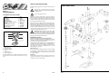
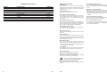
Refer to illustration below.
•
•
1
2
4
3
5
The drill should be mounted on a stable surface and
secured with suitable bolts/screws (not supplied)
through the two holes in the centre of the footplate
(13). Use washers as necessary to make sure the unit
is securely fixed – the footplate is cast iron, do not
over tighten the fixings.
Route the mains cable well away from the chuck and
front side of drill, ensure that it cannot get caught in
moving parts or the workpiece.
6
ASSEMBLY
7
8
Fasten the column to footplate
• Fasten the column (11) to footplate (13) with the
three bolts/washers/lock washers provided.
• Insert the bolts, with their washers, through the
flange on the column and screw finger tight into threads in footplate.
• Tighten with suitable spanner.
Slide the table assembly
• Slide the table assembly with the degree scale facing
up over the column and lock with the lever (6)
• Put the drill head assembly onto the top of the
column and slide down until the top of the column
hits the stop. Line up the front of the drill with front
face of foot and secure the drill head with the set pins
(8) using the 4mm Allen key provided,
Fit the chuck guard
• Fit the chuck guard (3) into the red housing on the
chuck
spindle
and
secure
with
the
bolts/washers/nuts provided.
• Do not operate this drill without the guard in place
and in the down position.
Fitting the drill chuck (9)
• Put the chuck guard in its upper position. Degrease
the inside of the chuck and the drill spindle using a suitable biodegradable solvent, dry off and push the
chuck onto the tapered spindle.
• Tap the chuck gently onto the spindle with a soft face
hammer.
9
10
6
11
12
13
ADJUSTING THE DRILL SPINDLE SPEED
Ensure the drill is unplugged from mains and the
drill is switched off.
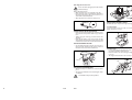
Refer to illustration below.
• Remove the crosshead screw on right hand side of
pulley cover (14) and open the cover.
• Loosen the thumbscrew (18) and push the motor
towards front of drill.
• Move the V-belt to set the desired speed; the speed
chart is on the inside of the pulley cover. Make sure
the V-belt runs parallel as illustrated on the chart, if
the belt is installed diagonally it will slip and wear out
quickly.
• Tighten the thumbscrew.
• Close cover and secure with crosshead screw.
• When you have changed speeds the V-belt tension
must be checked. See section below
Fit the depth adjustment levers
• Screw the three levers (5) into the boss on the left
hand side of the drill head hand tight.
• Run idle for 15 minutes.
• Check the V-belt tension (see section below) - start
the drill and run idle for 15 minutes to distribute the
factory-applied grease through out the bearings. This
is done only when using the drill for the first time.
14
15
17
18
4
Ferm
Ferm
5