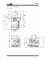
1
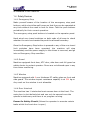
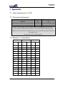
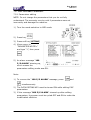
USER MANUAL
for
MBH Series
With Fanuc 0iM
Revised: June 2013
User Manual
MBH Series
CONTENTS
1.
Safety.......................................................................................................5
1.1
Intended Use ..............................................................................5
1.2
Important Safety Notice and Warning .........................................5
1.2.1
Safe installation ...................................................................5
1.2.2
1.2.3
1.2.4
1.2.5
1.3
1.4
Safety Cautions List....................................................................7
Safety Devices..........................................................................10
1.4.1
Emergency Stop ................................................................10
1.4.2
Guard ................................................................................10
1.4.3
1.4.4
1.4.5
1.5
1.6
2.
Machine guarding................................................................6
Software ..............................................................................6
Authorized personnel and training.......................................6
Safe working practice ..........................................................6
Window .............................................................................10
Door Interlock ....................................................................10
Cabinet door lock and switch............................................. 11
Warning Labels......................................................................... 11
Residual Risks.......................................................................... 11
Introduction...........................................................................................13
2.1
Consumption Material...............................................................13
2.1.1
Lubrication oil for linear rail and ballscrew.........................13
2.1.2
Lubrication oil for pneumatic system .................................13
2.1.3
Cutting fluid .......................................................................13
2.2
Operation Panel........................................................................14
2.3
Remote Jog ..............................................................................21
2.4
APC panel ................................................................................21
3.
2.5
2.6
Spindle Tooling .........................................................................21
Dimensions of work table..........................................................23
2.7
2.8
2.9
Workable zone..........................................................................23
Tool Magazine and ATC............................................................24
Chip Removal ...........................................................................24
Installation.............................................................................................26
3.1
Foundation Preparation ............................................................26
3.2
Power Preparation....................................................................27
3.2.1
Line Configuration .............................................................27
3.3
Unpacking.................................................................................28
3.4
Machine Lifting .........................................................................28
2
User Manual
MBH Series
3.5
3.6
Leveling of Machine..................................................................30
Before Power ON .....................................................................30
3.6.1
Grounding..........................................................................30
3.6.2
Power connection..............................................................32
3.6.3
Misc. ..................................................................................33
3.7
First Time Power ON ................................................................33
3.7.1
3.7.2
4.
5.
Rotation Direction of Motors ..............................................33
Spindle Run-in ...................................................................33
Operation...............................................................................................34
4.1
Power ON/OFF.........................................................................34
4.2
4.3
4.4
4.5
Automatic Power OFF ..............................................................34
Reference (or “ZERO RETURN” or “HOME”) the Machine ......34
Machine Warm-up ....................................................................35
Spindle Warm-up ......................................................................35
4.6
4.7
4.8
Interrupting Operation...............................................................35
Jobs Finished ...........................................................................36
Jog Axis ....................................................................................36
4.9
4.10
4.11
Jog Axis by MPG ......................................................................38
Tool Loading/Unloading ............................................................38
Large Tool management ...........................................................38
Maintenance ..........................................................................................40
5.1
Routine Inspection....................................................................40
5.1.1
Daily ..................................................................................40
5.1.2
Weekly (In addition to daily routine) ..................................41
5.1.3
Yearly (In addition to weekly routine).................................41
5.2
Lubrication................................................................................41
5.2.1
Automatic Lubrication System ............錯誤
錯誤!
錯誤 尚未定義書籤。
尚未定義書籤。
5.2.2
FRL unit.............................................................................41
5.3
Cleaning ...................................................................................42
5.3.1
Machine Interior:................................................................42
6.
Trouble shooting...................................................................................43
6.1
ATC system: .............................................................................43
6.2
APC system:.............................................................................43
6.3
Cooling, Coolant and lubrication system. .................................43
6.4
Door switch system ..................................................................44
6.5
7.
Alarm messages and remedies ................................................44
Appendix ...............................................................................................48
7.1
Power requirements: 45 kVA ....................................................48
3
User Manual
MBH Series
7.2
7.3
Pneumatic requirements...........................................................48
Spindle run-in procedures.........................................................48
7.4
7.5
M-function Codes .....................................................................49
User Definable Parameters ......................................................52
7.5.1
Parameters editing ............................................................52
7.5.2
Timer table.........................................................................53
7.5.3
Keep Relay list ..................................................................54
7.6
Machine floor space .................................................................57
7.6.1
MBH-3 ...............................................................................57
4
User Manual
MBH Series
1. Safety
1.1 Intended Use
This machine is a numerically controlled machine tool designed to
shape cold metal by the application of rotating cutting tools capable
of performing two or more machining processes (e.g. boring, drilling,
milling, thread tapping) at one set-up of a workpiece and
incorporating automatic facilities to:
Select and change tools from a magazine
Change the position of the workpiece relative to the spindle mounted
cutter.
Select and apply spindle speeds and axis feeds
Control ancillary services (e.g. coolant flow)
This machine is intended for use in an industrial environment and
must not be used in the residential, commercial and light industrial
environment.
Materials to be cut in this machine are: Steel, Iron, Iron casting,
Bronze, Brass, Copper, and Aluminium.
Materials not suitable to be cut in this machine are: Graphite, Wood,
Plastic, Magnesium alloy.
Consult the agent for the material not listed above.
1.2 Important Safety Notice and Warning
It is the user’s responsibility to be acquainted with the legal
obligations and requirements in the use and application of the
machine.
1.2.1 Safe installation
It is the customer’s responsibility to ensure the machine is installed
in a safe operating position, with all service pipes and cables clear of
the operation area so as not to cause a hazard. Access must be
allowed for safe maintenance, swarf and oil disposal including safe
stacking of machined and un-machined components.
5
User Manual
MBH Series
1.2.2 Machine guarding
This Machine is fitted with completely enclosed guards as standard.
In certain cases and tooling applications additional guarding may
have to be provided by the user.
The standard machine guarding has special safety interlocks on the
guard doors that comply with the Machinery Directive. Guards and
interlocks must be kept fully maintained and tested by the customer
and shall not be removed.
The guards are made with clear observation windows having high
impact resistance to provide operator safety and a clear
unobstructed view of the operations in process. The opening of any
guard door provides access to potential hazard areas. Opening of the
front working area guard doors is not allowed whilst the spindle is
rotating but it is still possible to manually initiate axis movements
whilst these doors are open albeit at a reduced traverse rate.
Extreme care must therefore be used at all times.
1.2.3 Software
Unauthorized changing of machines software or control parameters
is hazardous and is not permitted. The machine maker will not
accept any liability whatsoever for unauthorized changes in this
area.
1.2.4 Authorized personnel and training
Operating, service and maintenance engineers shall be authorized
by the ‘User Company’ and properly trained in the use of the
machine.
1.2.5 Safe working practice
Workholding devices, lifting equipment, tooling and their use shall be
the responsibility of the user. It is the user’s responsibility to protect
against the hazards caused by swarf, leaking oil or coolant and their
use.
Use of proprietary oil or coolant is the responsibility of the user.
Special instructions from the suppliers concerning their use should
6
User Manual
MBH Series
be carefully read and understood before use.
To prevent body injury, safe working practices should be employed
when operating or servicing the machine.
1.3 Safety Cautions List
It is the user’s responsibility to ensure all local regulations and safety
instructions are followed.
Users should consult with their own safety representative to ensure
that all such regulations are known and acted upon.
DON’T run the machine until you have made clear to your supervisor
that you understand the potential hazard of spindle rotation, the
throwing of coolant and the throwing of swarf from the cutting
process.
DON’T run the machine until you have read and understood all
manuals provided with the machine.
DON’T run the machine for the first time without a qualified
instructor. Ask your supervisor for help when you need it.
DON’T get caught in moving parts. Remove watches, rings,
jewellery, neckties and loose fitting clothes.
KEEP your hair away from moving parts.
PROTECT your eyes. Wear safety glasses with side shields at all
times.
PROTECT your head. Wear a safety helmet when working near
overhead hazards.
PROTECT your feet. Always wear safety shoes with steel toes and oil
resistant soles.
PROTECT your hands. Make sure the spindle is stopped before
manually changing a tool.
PROTECT your hands. Make sure the spindle is stopped before
manually changing a workpiece.
PROTECT your hands. Make sure the spindle is stopped before
manually clearing away swarf or oil. Use a brush or chip scraper.
NEVER use you hands.
PROTECT your hands. Make sure the spindle is stopped before
7
User Manual
MBH Series
manually adjusting the work piece or fixture or coolant nozzle.
PROTECT your hands. Make sure the spindle is stopped before you
take measurements.
PROTECT your hands. Make sure the spindle is stopped before you
move a safeguard. Never reach round a safeguard.
PROTECT your hands. Make sure the machine is switched off and
electrically isolated before making any mechanical adjustment.
PROTECT your hands. Beware sharp edges of cutting tools when
changing and handling tools.
PROTECT your eyes and the machine. Never use a compressed air
hose to remove swarf or to clean out air vents.
Gloves are easily caught in moving parts. TAKE THEM OFF before
you turns on the machine.
Loose objects can become flying projectiles. REMOVE all loose items
(wrenches, chuck keys, rags etc.) from the machine before starting.
PREVENT objects from flying loose. Securely clamp and locate the
work piece.
NEVER operate a machine tool after taking strong medication, using
non-prescription drugs, prescription drugs or consume alcohol which
may impair concentration.
ALWAYS make sure the working and cutting zone is safeguarded.
KEEP the work area well lighted. Ask for additional lighting if
needed.
DON’T slip. Keep your work area clean and dry. Remove swarf, oil
and obstacles.
NEVER lean on the machine. Stand away when machine is running.
DON’T get trapped. Avoid pinch points caused between other
machines and the machine you are working.
PREVENT cutter breakage. Use correct cutter speed and axis feed
rate for the job. Make manual over ride adjustments of axis feed rate
or spindle speed if you notice unusual noise or vibration. Ask your
supervisor for help if you need it.
PREVENT cutter breakage. Rotate the spindle in a clockwise
direction for right handed tools, counter clockwise for left handed
tools. Use the correct tool for the job.
8
User Manual
MBH Series
PREVENT work piece and cutter damage. Never start the machine
when the cutter is in contact with the work piece.
Dull and damaged tools break easily. Inspect tools and tool holders.
Keep tools sharp. Keep overhang short.
KEEP all lubrication reservoirs maintained at the correct level.
Always keep to the maintenance schedule.
Certain materials such as magnesium are highly flammable in dust
and chip form. See your supervisor before working these materials.
PREVENT fire. Keep flammable liquids and materials away from the
work area and from hot swarf.
PREVENT the machine from moving unexpectedly. When leaving
the machine unattended, not producing, leave switched in the
MANUAL mode.
DON’T use the machine in a volatile atmosphere. Electrical devices
fitted to the machine are for normal factory use and are not
explosion proof.
ALWAYS keep the machine clean and do not let swarf collect.
ALWAYS keep the area around the machine clean and tidy. Opening
the guards creates the potential for residual coolant and swarf to fall
to the swarf tray and possibly to the floor. Good housekeeping
minimizes the potential for trips, slip or fall of all personnel.
INFORM all other personnel who approach the machine about the
hazards described in this safety list.
When making adjustments with spanners, always ensure that the
required leverage is safely applied. Always avoid slippage. Always
apply the leverage by pulling, never by pushing. Always use the
correct size spanner. Ensure the spanner is not damaged.
Do not use organic chemical solvents to clean the machine guards or
compressed air services equipment.
The windows are manufactured from bulletproof polycarbonate
sheet. This material does deteriorate with age, and should be
exchanged within the time period described later in this manual.
Any workholding device used in conjunction with this machining
centre must fit within the working envelope available. Under no
circumstances must any such workholding device be used when it
would require the need to override/defeat the safety interlocks fitted
9
User Manual
MBH Series
as standard to this machine.
1.4 Safety Devices
1.4.1 Emergency Stop
Make yourself aware of the location of the emergency stop push
buttons, which should be well known so that they can be operated at
any time without the need to look for them. Test the push buttons
periodically for their correct operation.
The emergency stop push buttons is located on the operator panel.
Hard wired over travel switches on both ends of all axes to check
whether the axis has traveled beyond the allowed boundary.
Once the Emergency Stop button is pressed or any of the over travel
limit switches have been operated, the machine will stop
immediately and the power supply to the drives is removed, and go
into an Emergency Stop condition
1.4.2 Guard
Machine equipped front door, ATC door, side door and full guard as
safety device to protect operator. Doors are not allowed open in any
time when machining.
1.4.3 Window
Machine equipped with 6 mm thickness PC safety glass on front and
side guard. The window impact resistance capacity is at 520 kg.m.
Any crack on the window is not allowable.
1.4.4 Door Interlock
The machine has 1 interlocked main access door at the front. The
main door is shot bolted shut and can only be opened once the
spindle is stationary and there is no program running.
Power On Safety Circuit (Allows the operator to execute certain
tasks whilst the front door is open)
10
User Manual
MBH Series
Limited machine functionality is available to the operator whilst the
main door is open. The handwheel and jog keys are allowed to move
the machine axes at feed rates of 2000 mm/min and less. Spindle
operation is prohibited whilst the main door is open as the spindle
contactor is hard wired through the door interlock switch. Selection
of automatic program running is prohibited until the doors are shut.
1.4.5 Cabinet door lock and switch
The main power switch of machine must be shut
off and turned further CCW to open the cabinet
door.
1.5 Warning Labels
Most of the warning labels are self-explained as
following:
1.6 Residual Risks
The machine tool has been designed and manufactured to the
highest standards, but still, your attention is drawn to the following
RESIDUAL RISKS existing within the machine.
11
User Manual
MBH Series
Always check that the cutting tool product you are using is
approved to run at the selected speed.
If non suitable cutting conditions are selected, coolant can
splash, and swarf can escape over the sides of the guard.
Failure of the gravity-affected-axis servo motor brake could
allow the head to fall when the power is OFF
Do not operate the machine with the side door access panels
removed.
Isolate the machine before cleaning the machine through the
side door access panels
12
User Manual
MBH Series
2. Introduction
2.1 Consumption Material
2.1.1 Lubrication grease for linear rail and ballscrew
Qt’y
Recommended grease (brand)
700 c.c./can
LHL-X100-7 (LUBE)
2.1.2 Lubrication oil for pneumatic system
Oil for pneumatic system is recommended to use same specification
of ESSO TERESSO 32 or SHELL TELLUS OIL 32. Total quantity oil for
machine in every half year need 120 cc.
2.1.3 Lubrication oil for oil-air built-in motor spindle
Qt’y
Recommended oil, ISO VG68 (brand)
700 c.c./can
Azolla ZS 68 (Total)
DTE oil 16 (MOBIL)
Tellus oils 68 (SHELL)
2.1.4 Cutting fluid
Cutting fluid and mixing ratio with water are recommended by
following table.
Marker: Castrol
No.
Type
Application
Dilution ratio
with water
1
SYNTIOL-9913
Aluminum cutting only
1:15
2
ALUSBL-B
Aluminum cutting only
1:15
3
HYSOL-X
Various material cutting
1:20
13
0
20
40
60
50
60
80
0
80
100
25
200
120
140
50
100
120
180
160
140
100
200
180
160
ZRN
AUTO
液削切
率給進
RAPID
屑吹削切
轉正軸主
率給進動快
行執帶紙
EDIT
刷沖座底
止停軸主
車試
行執節單
JOG
轉反軸主
向軸
止停擇選
略跳節單
式模動自
速轉
歸復點原
令指動手
式模輯編
輪手
動快
動寸
HANDLE
動啟式程
轉正庫刀
下/上杯刀
轉正
轉反庫刀
止停/轉反
位定軸主
能功
)線劃不(孔開不膜薄
、孔開金鈑
定鎖輯編
式模
14
刀換動手
能功助輔
能功助輔
示顯
MDI
止停式程
止停急緊
源電
DNC
User Manual
MBH Series
2.2 Operation Panel
User Manual
MBH Series
(1) Power ON: Turn ON the power of the controller.
(2) Power OFF: Turn OFF the power of controller.
(3) Mode selection: From Left to right, CW.
MDI
手動指令
HANDLE
手輪
DNC
紙帶執行
JOG
寸動
編輯模式
EDIT
RAPID
AUTO
原點復歸
自動模式
快動
ZRN
AUTO: Program execution mode.
EDIT: Program editing mode.
DNC: PC connection mode.
MDI: Manual Data Input mode. (single block command, tool offset, etc…)
HANDLE: Axis movement by hand wheel on Remote jog unit.
JOG: Slow movement of axis.
RAPID: Rapid moving axis in JOG mode.
ZERO RETURN: Return to the zero point of each axis.
(4) Feed rate override:
Effective for commands or program in MDI, AUTO or
DNC modes. Override from 0% to 200%.
15
User Manual
MBH Series
(5) Rapid movement speed override:
Effective in modes RAPID, ZERO RETURN or the
commands G00 in program execution.
(6) Spindle speed override:
(7) Over travel alarm release:
Once the axis moved over travel and machine halted, keep
pressing this button and jog the axis away from travel limit. Then
zero return the axis.
(8) Single block execution:
Only one block will be executed when the CYCLE START was
pressed, if this switch was turned ON.
(9) Ignore marked blocks:
Blocks with “/” marked will be ignored if this switch was ON.
(10) Dry run:
In AUTO, MDI or DNC modes, the “F” command will be overrided
by JOG, if this button was ON. G00 will also be overrided if proper
parameter was set.
(11) Air blow (optional):
Compressed air will be ON at blowing nozzle, if this button was
ON.
The compressed air will be OFF, if there were commands M06,
M00 or M01 in program.
M14 will turn ON the compressed air and M15 will turn it OFF.
(12) Work lamp:
Turn the work lamp ON or OFF.
16
User Manual
MBH Series
(13) Optional program halt:
M01 will be effective (program halted) if this button was ON. Need
to press CYCLE START to resume program execution.
(14) Coolant:
Coolant pump will be activated if this button was ON and vise
versa.
In AUTO mode, coolant pump will be activated by M08 command
or stopped by M09 or this button.
(15) Chips wash down:
Chips wash down pump will be activated if this button was ON
and vise versa.
In AUTO mode, coolant pump will be activated by M13 command
or stopped by M16 or this button.
(16) F1 – F4 switches: reserved.
(17) Chip conveyor forward (optional): Effective in AUTO and manual modes.
Chip conveyor will move forward if this button pressed.
(18) Chip conveyor reverse (optional) : Effective in AUTO and manual modes.
Chip conveyor will reverse if this button pressed. Re-pressed this
button will stop the chip conveyor.
(19) Manual Tool Change:
Effective in JOG mode. Spindle must be oriented priorly.
(20) Tool magazine CW:
Effective in manual mode.
(21) Tool magazine CCW:
Effective in manual mode.
17
User Manual
MBH Series
(22) Spindle CW:
Effective in manual mode.
“S” command must be inputed in AUTO or MDI modes. Then
change modes to manual and press this button.
(23) Spindle STOP: Effective in manual mode.
(24) Spindle CCW:
Effective in manual mode.
“S” command must be inputed in AUTO or MDI modes. Then
change modes to manual and press this button.
(25) Data editing key switch:
Effective in EDIT and MDI modes.
Program, Tool data, Work coordinate data and diagnostic
parameters CANNOT be edited if this switch was turned OFF.
(26) Cycle START:
Effective in AUTO mode.
In MDI mode, type in single block command and press this button
to execute it.
In AUTO mode, press this button to execute the program in
memory.
In DNC mode, press this button to execute the program in memory of
external devices. (PC or tape machine)
Resume the program execution which was halted by Feed HOLD.
(27) Feed HOLD:
Effective in AUTO mode.
Halt the programe execution: Axis movement will be stopped, yet
the spindle keeps spinning.
18
User Manual
MBH Series
(28) Emergency STOP:
Any mechanical movement will be stopped. Power of
servo system will be cut OFF. Rotate the knob CW to
release it.
(29) +X axis movement:
Effective in JOG mode.
Move X axis in positive direction.
(30) +Y axis movement:
Effective in JOG and ZERO RETURN modes.
Move Y axis in positive direction.
(31) +Z axis movement:
Effective in JOG and ZERO RETURN modes.
Move Z axis in positive direction.
(32) +4 axis movement:
Effective in JOG and ZERO RETURN modes.
Move 4th axis in positive direction.
(33) -X axis movement:
Effective in JOG and ZERO RETURN modes.
Move X axis in negative direction.
(34) -Y axis movement:
Effective in JOG mode.
Move Y axis in negative direction.
(35) -Z axis movement:
Effective in JOG mode.
Move Z axis in negative direction.
(36) -4 axis movement:
Effective in JOG mode.
19
User Manual
MBH Series
Move 4th axis in negative direction.
(37) Axis ZERO point indication lamps: Lamp light up when each axis moved
to zero point.
20
User Manual
MBH Series
2.3 Remote Jog
Axis selection
Movement of one
division (1 or 10 or
100 µm)
100 divisions/round
CW: positive
CCW: negative
2.4 APC panel
Emergency Stop
Ready: Press this button to manually
change the pallets. If the lights flashes
after pressing the button, check whether
the front door closed or lock pin inserted.
Both hands: Must be pressed together
while pressing A or B or C.
M52/53: Fixture 1 clamp and unclamp.
M54/55: Fixture 1 clamp and unclamp.
M56/57: Fixture 1 clamp and unclamp.
Light: External lights
2.5 Spindle Tooling
Tooling with a balance level of G2.5 or better should always be used.
Failure to do so will reduce spindle life and surface finish and may
21
User Manual
MBH Series
invalidate the machine warranty.
For safe operation, make sure the tool holder and pull stud
combination meet the standard below:
22
User Manual
MBH Series
2.6 Dimensions of work table
2.7 Workable zone
23
User Manual
MBH Series
2.8 Tool Magazine and ATC
Tools magazine
Tool Change Arm
ATC cam box
2.9 Chip Removal
24
User Manual
MBH Series
Chips were washed away from the interior of machine and flow into
the chute where the chip screw augers or chip conveyor located.
Then chips were collected at the exit of screw auger or conveyor.
25
User Manual
MBH Series
3. Installation
3.1 Foundation Preparation
The machine should be sited on a flat area (maximum fall 3mm in 3
m) free from cracks and expansion joints.
The composition of the floor and sub-structure should be of suitable
construction to bear the weight of the machine. Any friable areas
should be made good using recognized building construction
techniques. If doubt exists we recommend you consult your building
architect.
26
User Manual
MBH Series
3.2 Power Preparation
3.2.1 Line Configuration
The machine is designed to operate from a
3-phase AC incoming power source with an
earth star point, as shown in the right. This
incoming line short circuit current must be
at least 2kA.
27
User Manual
MBH Series
In other cases, such as those examples shown in figures below, an
isolating transformer of 15kVA or larger capacity with an earth
grounded WYE secondary is required between the incoming lines and
the machine. The incoming line short circuit current must again be
least 2kA.
Other Incoming Line Configurations
3.3 Unpacking
The machine was fixed on a skid during which could be pulled to the
opening of container and then moved by a fork lifter.
Select a chain according to the weight of the machine. Tie the chain
to the skid and make sure the connection is secured. Slowly pull the
machine and monitor the gap between the machine and the wall of
the container.
3.4 Machine Lifting
Any lifting cables and slings must be rated to take the machine’s
weight.
28
User Manual
MBH Series
If the machine is to be lifted by Fork Truck, the minimum capacity
should be 120% of the machine weight and with a minimum tine
length of 2,000mm.
29
User Manual
MBH Series
3.5 Leveling of Machine
a) Make sure the location of the machine is exactly where you need
it to be. Ensure allowance for access for operation, cleaning and
maintenance is provided. See the installation dimensional
drawing for minimum clearances.
b) Locate the floor pads which are packed with the associate kit and
position them on the floor under each jack bolt. When satisfied
lower the machine gently onto the pre-located pads. Ensure jack
bolts are screwed down to provide a 10 to 15mm gap from the
underside of the base casting to the floor.
c) If you use skates then employ the jack bolts with suitable support
packing to raise the machine enough to remove the skates and
finally set onto the floor pads.
3.6 Before Power ON
3.6.1 Grounding
a)
The machine must be grounded in order to protect personnel
30
User Manual
MBH Series
and the machine from electrical hazards. Grounding must be in
accordance with the standards for electrical equipment.
b)
c)
d)
Ideally, the grounding point should be as close as possible to the
machine.
A qualified electrician must carry out the grounding work,
otherwise serious injury, death, or accidents involving machine
damage could result.
The machine must be grounded in one of the following ways:
1) Independent grounding
2) Common grounding
Regardless of the type of grounding system used, the earth loop
impedance of the supply, which connects the machine to
ground/earth, must not exceed 1 ohm.
e) Never ground the machine in the manner shown in the
illustration below.
No more than one grounding conductor wire can be connected to a
single terminal. If the grounding conductors are connected in the
manner shown in the illustration above, a faulty connection at one of
the terminals could cause grounding current to be fed back to the
31
User Manual
MBH Series
machine, resulting in serious accidents.
Once the electrical and air supplies are provided make the
connection to the machine. The delivery dimensional drawing gives
details of input locations.
ON NO ACCOUNT MUST YOU SWITCH ON THE MACHINE.
WE PREFER YOU TO REMOVE YOUR ISOLATOR FUSES OR TRIP
CIRCUIT BREAKERS.
3.6.2 Power connection
A qualified electrician should only carry out connection of the power
lead to the machine.
Cables, cords or electric wires of which insulation is damaged can
produce current leaks and electric shocks. Check their condition
before connecting.
Ensure the power cable to the machine main isolator has sufficient
current carrying capacity to handle the electric power used.
Cables which must be laid on the floor, must be protected against
chips, oil and coolants penetration, which might cause damage.
In the event of power failure, turn off the main circuit breaker
immediately.
Fuses and circuit breakers should be replaced only with suitably
rated alternatives. Safety devices should be replaced only with the
machine manufacturers recommended parts.
Protect the CNC unit, operating panel, and electric cabinet etc from
shocks which could cause a failure of malfunction.
Connect the power cable to main
power terminal block. Ensure the
32
User Manual
MBH Series
sign rotation of R, S, T phases.
Connect the ground cable to the Earth bar.
3.6.3 Misc.
Check the condition of the warning labels. If they are missing or
become illegible, order replacements from your distributor according
to the part number on the label plate. Do not remove warning labels.
After unpacking the machine clean all rust preventatives from the
machine with a non-volatile cleaning fluid. Lightly lubricate each
sliding part before trying to operate the machine. Manually operate
the lubricating oil pump until oil oozes out from the slide way wipers.
Oil volume should be filled to the indicated level. Check and top up if
necessary.
Use recommended oil brands and appropriate levels for all
lubricating systems. See the instruction plate at the rear of the
machine.
The coolant system comprises of a separate tank which houses the
coolant pumps and is located beneath the front and left sides of the
machine.
3.7 First Time Power ON
3.7.1 Rotation Direction of Motors
The rotation of 3-phase motors of pumps, chips removal and fans
might be reversed due to the different phase sequence of city power
U, V and W. Please confirm the rotation of all the coolant pumps and
cooling fans.
3.7.2 Spindle Run-in
The grease inside the bearings of spindle might be concentrated by
gravity due to temperature variation during the transportation and
storage. It is a MUST to run the spindle following the procedures
described in Appendix.
33
User Manual
MBH Series
4. Operation
4.1 Power ON/OFF
Never turn off power during automatic operation or with the spindle
or axes running unless an emergency occurs. It is better to interrupt
the program by pressing the "Cycle Stop" push button.
Ensure that all Emergency Stop Buttons are unlocked.
Turn the machine on at the isolator.
Press the power ON button on the control panel and the
machine will take a few moments to boot up.
4.2 Automatic Power OFF
Find the software switch in “offset”
screen. Turn the switch ON and the
control will shut power OFF once M30
was executed in CNC program.
4.3 Reference (or “ZERO RETURN”
or “HOME”) the Machine
1) Turn the mode selection switch to ZERO RETURN.
2) Press +Z button, Z axis should move
upward until the ZERO POINT
INDICATION LAMP light up.
3) Press –X, +Y, +4, +5 buttons. Axes will
34
User Manual
MBH Series
move until the ZERO POINT INDICATION LAMP light up.
Note: If any of the Machine axes are already over the referencing
point, it may be necessary to manually move the axis away in jog
mode before beginning the reference procedure.
4.4 Machine Warm-up
** If the machine is used to produce components immediately after
being started, following a long idle period, sliding parts may be worn
due to lack of oil and thermal expansion of the machine can
jeopardize machining accuracy. To prevent this condition, always
warm the machine up. **
We recommend that the machine is ‘Warmed up’ prior to operation
by running all axes for 20 minutes at the speed of actual cutting in
the automatic operation mode. The spindle speed should be
gradually increased up to actual cutting speed.
4.5 Spindle Warm-up
If the following procedures are not followed, spindle life will be
reduced significantly. Follow the speed and running time duration in
the table for each type of spindle. Please note that the duration is
either in minutes (m) or in seconds (s).
Spindle speed (% of max. speed)
Duration (minutes)
Daily
20%
10
Spindle stopped more
20%
10
than 72 hours
50%
10
Spindle stopped more
20%
15
than 2 weeks
40%
15
60%
30
80%
30
100%
40
4.6 Interrupting Operation
35
User Manual
MBH Series
When leaving the machine temporarily after completing a job, turn
off the power on the operator panel with the Emergency
Stop button and turn off the main isolator.
4.7 Jobs Finished
Always clean the machine and supporting equipment down after use.
Remove and dispose of chips and clean the covers and windows etc.
Return each machine component to its initial condition.
Check wipers for damage and replace if necessary.
Check coolants, hydraulic oils and lubricants for level &
contamination. Change them if you suspect they are contaminated.
Clean the filter on the top of the coolant tank.
Turn off the power first on the control panel with the emergency stop
button and then at the main isolator before leaving the machine at
end of the shift.
4.8 Jog Axis
To manually jog an axis, first turn the mode selection switch to JOG
mode.
Turn the axis movement override to desired speed.
(0-3000mm/min)
36
User Manual
MBH Series
Press the button corresponding to the desired axis and direction.
For rapid movement, press the RAPID MOVEMENT button together
with button of desired axis and direction.
The feed rate of RAPID JOG can be overrided by RAPID MOVEMENT
SPEED override. (F0% and 100% are set in parameters)
37
User Manual
MBH Series
4.9 Jog Axis by MPG
To manually move axis using the Handwheel, first turn the mode
selection switch to HANDLE mode. Then use the knobs and MPG on
remote jog box.
4.10 Tool Loading/Unloading
Switch to JOG or HANDLE mode.
Open guard door of machine.
While holding the tool, press and hold the
clamp/unclamp button on the machine head to
release the tool (See illustration). Replace tool
and release the button to clamp.
Close guard door of machine.
Using AUTO or MDI, load the correct tool number into the Magazine.
4.11 Large Tool management
Large tool is the tool with diameter larger than the allowable
diameter as described on the label near tool magazine. This kind of
tool can be used, providing the adjacent tool pots are empty.
For arm type tool changer, the tool number is independent to the pot
number of magazine. Therefore a carefully management of the tool
number of large tool is necessary.
In this machine, the large tools are set prior to standard tools and
are fixed in pots with least pot number.
All the user has to do is to determine the number of large tools need
38
User Manual
MBH Series
to be used and set this number in D63.
Procedure to input the tool information:
1) Switch to HANDLE mode.
2) Refer to the section “Parameters editing” in Appendix to enter
the parameters editing screen.
3) DATA EDITING KEY must be turned ON.
4) Press
△
5) Press
to next page.
6) Press softkey [PMCMNT]
△
7) Press
to next page.
8) Press softkey [DATA]
9) Enter the tool information to related address.
Example:
Address
data
Meaning
D63
D63
D63
D63
0
1
2
3
No large tools
One large tool (#1 ) and stored at Pot #2.
Two large tools (#1 ) and stored at Pot #2, #4
Three large tools (#1 ) and stored at Pot #2, #4, #6
Note: The maximum large tools number is half of the pots number in
the magazine.
39
User Manual
MBH Series
5. Maintenance
DANGER!
Before carrying out any maintenance work, ensure that the
machinery is switched off and disconnected from the main power
supply. Also ensure that the necessary warning signs and /or locks
are appointed to stop any unauthorized persons from switching the
power on to the machine until the work is complete and the
machinery is safe to operate.
The above warning signs or indications should be secured by a
semi-permanent means with the printing clearly visible.
Only qualified and competent maintenance engineers should carry
out machinery maintenance work. Working on live electrical
equipment must be carried out by only suitably qualified electricians.
WARNING!
Over travel limit switches, proximity switches and interlock
mechanisms including all functional parts should not be removed or
modified.
When working in high places, use steps or a ladder which are
maintained daily for safety.
Use only fuses,
manufacturers.
cable's
etc.
from
reputable
recognized
CAUTION!
The maintenance person should check that the machine operates
safety after the work is completed. Maintenance and inspection data
should be recorded and kept for reference.
5.1 Routine Inspection
5.1.1 Daily
40
User Manual
MBH Series
1. Check pressure gauges for proper reading. Air pressure
5.5bar (80psi). Hydraulic pressure 68bar (986psi)
2. Check that there is sufficient oil in the air lubricator.
3. Check motors and other parts for abnormal noises.
4. Check the lubrication of sliding parts for evidence of proper
lubrication.
5. Check safety covers and safety devices for proper operation.
6. Check coolant level and fill as necessary.
7. Clean dirt and chips from the axes and empty the swarf trays.
5.1.2 Weekly (In addition to daily routine)
1. Clean chips and dirt from the entire machine and wipe down.
2. Check the air filter at the rear of the electrical cabinet. Replace
the filter element if it is contaminated.
3. Check all polycarbonate vision panels for signs of damage –
crazing, cracking etc. or reduced visibility and replace if
necessary. Contact your distributor for details.
4. Check the spindle cooler/chiller is running properly and the
coolant temperature is near the temperature setting.
5. Check the spindle front draining hole from labyrinth is not
jammed by dirt.
6. Check the air purging at the spindle nose. Run the spindle for
10 seconds and stop. Listen or feel the air flowing from the
gap between the spindle shaft and housing.
5.1.3 Yearly (In addition to weekly routine)
1. Remove the filter from the air filter bottle and clean/replace.
2. Check spindle drive belt condition and tension.
3. Check lost motion.
4. Check the condition of the linear rail wipers.
5. Check the integrity of the electrical connections and inspect
the condition of the insulation.
6. Check condition of coolant filters and replace if necessary.
5.2 Lubrication
5.2.1 FRL unit
FRL unit offer air cleaning and air lubricating function. The
lubricating oil discharge rate could be adjusted by a knob on FRL
unit.
41
User Manual
MBH Series
5.3 Cleaning
5.3.1 Machine Interior:
Chip might spatter and accumulated inside of MAGAZINE guard or
somewhere that washdown coolant can’t reach after machining.
Oil/coolant condensation might be accumulated inside of HeadStock
and effect machine operating in good condition. It needs to be check
or clean out.
42
User Manual
MBH Series
6. Trouble shooting
6.1 ATC system:
1. Tools falling down when arm rotating:
Tool can not be clamped well due to arm grip or stop pin is seized or
arm and spindle are not aligned.
2. Arm not stopped at home position (for example: Emergency Stop
Button was pressed during tool changing):
1) Change to JOG mode.
2) Press the button Manual Tool Change for 3 seconds,
the lamp of CYCLE START button will start flashing.
3) Press the CYCLE START button, the arm will move forward a little
bit.
4) Keep pressing CYCLE START button until the arm reach home
position. Pay attention to any potential interferences along the
path of arm swinging.
5) Press RESET to clear all alarms.
6) Confirm the tool number registered to actual tools in magazine.
6.2 APC system:
1. Arm not stopped at home position (for example: Emergency Stop
Button was pressed during tool changing):
1) Confirm no potential interference.
2) Conform the front door closed and lock pin inserted.
3) Change to JOG mode.
4) Press the button READY at the APC panel for 3 seconds, the lamp
of READY button and CYCLE START button will start flashing.
5) Press the CYCLE START button, the APC will finish the
movement.
6) Confirm the pallets are located in right position and well locked.
7) Press RESET to clear all alarms.
8) Confirm the pallet number is correct.
6.3 Cooling, Coolant and lubrication system.
1. Lubrication oil level too low
Refill lubrication oil into tank
2. Lubrication pressure too low
43
User Manual
MBH Series
Refill lubrication oil or replace whole lubricator unit.
3. Coolant pumps noise.
Pump sealing is break down or chip materials invade into pump.
6.4 Door switch system
1. Front door is opened
Close front door or replace interlock switch
6.5 Alarm messages and remedies
Alarm No.
Alarm Message
Cause
Remedy
1001
SAFETY DOOR NEED
CLOSE!
Door not close
Key not inserted into
switch properly
Safety switch malfunction
Close the door
Re-align the key with safety
switch
Replace safety switch
1003
SPINDLE ALARM!
1004
SP GEAR SHIFT
ALARM!
1005
ATC NOT READY!
1007
TF<= 0 COMMAND
ERROR!
Tool number smaller than
0!
Press RESET and correct the T
code.
1008
TF IS NOTHING IN
TOOL BOX
Tool number not
registered in tool table!
Press RESET and correct the T
code.
1009
MAG PMM SERVO
ALARM!
Turn the machine power OFF and
ON. If the problem still existed,
contact the service of controller.
1010
MAG PMM BATTERY
ALARM!
Contact the service of controller.
1011
MAG (C0) SETTING
ERROR!
1012
YZ IN DANGER AREA!
1013
MAG NOT READY!
1014
SP.ORI
1015
MOTOR OVERLOAD!
ALARM!
Check the alarm number from
controller or from the inverter and
contact the service of controller
See troubleshooting.
NC parameters (No.
4000-4099) not corrected.
Correct the parameters and press
RESET.
Motors of the following
tripped overload
contactor or fuse burned.
Check any debris jammed in the
transmission. Clear the debris,
reset the overload contactor or
replace the fuse. Then press
RESET.
Coolant (-F213)
Chip conveyor (-F217,
-F218)
Lube unit (-A204)
44
User Manual
MBH Series
Alarm No.
Alarm Message
Cause
Remedy
CTS (-F237)
Chip wash down (-F232)
1017
AXIS OIL MATIC
ALARM!
1019
M6 SWAP POSITION
MISSED!
1020
SPINDLE OIL MATIC
ALARM!
1021
TOOL MEASURE
ALARM!
1022
TOOL LIFE EXHAUST!
1026
JIG NEED CLAMP!
1027
AIR PRESSURE
FAILED!
1028
ATC (D52) SETTING
ERROR!
1029
SP TOOL CLAMPING
FAILED!
1030
MAG (D51) SETTING
ERROR!
1032
AUTO DOOR CLOSE
FAILED!
1034
SP TOOLS OVERLOAD!
1035
WORKPIECE
MESUREMENT ERRO
1036
OIL AIR LUBE ERROR!
1037
DC24V POWER
SUPPLY ERROR!
1038
OVER CYCLE ALARM!
1039
BIG TOOL RESET
1040
SP MIST OIL AIR
PRESSURE LOW!
1041
B AXIS
CLAMP/UNCLAMP
ERROR!
1046
WORKPIECE PROBE
LOW BATTE
Oil level in spindle oil
cooler too low.
Refill the spindle oil cooler. Then
press RESET.
Spindle clamping sensor
not adjusted properly.
Poor wire connection to
spindle clamping sensor.
Spindle clamping sensor
malfunction.
Adjust the sensor conforming to
the clamping/unclamping stroke.
45
Improve the wiring.
Replace the sensors.
User Manual
MBH Series
Alarm No.
Alarm Message
1058
ATC DOOR NOT
CLOSE!
1059
ATLM COVER NOT
OPEN
1061
ATC CYCLE FAILED
1063
ARM POSITION NOT
HOME!
1065
NONE TF COMMAND!
1084
APC (D53) SETTING
ERROR!
1089
APC PMM SERVO
ALARM!
1090
APC PMM BATTERY
ALARM!
1091
WORK TABLE NOT
UNCLAMP!
1092
APC TABLE NOT
UNCLAMP!
1093
APC CHANGE ERROR!
1094
APC CHANGE TIME
OVER
1095
WORK TABLE
AIRTIGHT ERROR!
Cause
Remedy
Turn the machine power OFF and
ON. If the problem still existed,
contact the service of controller.
Air pressure not enough.
Check air pressure.
Pressure sensor not set
properly.
Adjust the pressure sensor.
Work table was not laid
down properly.
1096
APC CHANGE ARM
AIRTIGHT AL!
2000
GEAR NEUTER!
2001
NOT ON TOOL
CHANGE POINT!
2002
CHANGE GEAR
CROSSPIECE FA
2003
LUBE OIL LEVEL TOOL
LOW!
2004
LUBE PRESSURE
TOOL LOW!
2005
PLEASE CLOSE MAG
DOOR!
2006
APC SAFETY DOOR
NOT REDAY
46
Check any debris interfering
between work table and cones.
User Manual
MBH Series
Alarm No.
Alarm Message
Cause
Remedy
2008
PARTS COUNT
ARRIVE!
2016
MAG DOOR NOT
CLOSE!
2017
SPINDLE OIL LEVEL
LOW!
2022
CTS OUT PRESSURE
SWITCH!
2023
CTS OUT FILTER
OBSTRUC!
2024
CTS AUXILIARY LEVEL
LOW!
2031
PLEASE CHECK AB
TABLE POSITION!
2032
APC TABLE NOT
READY!
2033
APC TABLE ROT NOT 0
DEG
The lock pin not inserted
properly at pallet at
pre-zone.
Insert the lock pin properly and
then press RESET.
2034
APC DOOR NOT
CLOSE
The lock pin not inserted
properly at pallet at
pre-zone.
Insert the lock pin properly and
then press RESET.
2036
WORK TABLE
UNCLAMP
2040
MACHINE GUARD IS
OPEN!
Press the READY button on APC
panel.
47
User Manual
MBH Series
7. Appendix
7.1 Power requirements: 45 kVA
7.2 Pneumatic requirements
Unit
Value
Pressure
bar
> 5.5
Flow rate
Litre/min
> 400
Dew point (at ATM. Pressure)
°C
-17 or lower
Note: The air supply must be clean (40micron particulate size) and dry.
Do not connect direct to a compressor with a short pipe as water/oil may
condense out and cause a potential seizure of the spindle bearings through the
air purge circuit.
An air drier unit is recommended.
7.3 Spindle run-in procedures
12000 rpm
Speed
10000 rpm
Time
(rpm)
Speed
8000 rpm
Time
(rpm)
Speed
Time
(rpm)
1000
5m
1000
5m
1000
5m
5000
3s
5000
3s
5000
3s
2000
5m
2000
5m
2000
5m
10000
3s
10000
3s
9000
3s
3000
5m
3000
5m
3000
5m
12000
3s
--
--
--
--
4000
5m
4000
5m
4000
5m
5000
5m
5000
5m
5000
5m
6000
5m
6000
5m
6000
5m
7000
5m
7000
5m
7000
5m
8000
5m
8000
5m
8000
5m
9000
5m
9000
5m
10000
5m
10000
5m
11000
15 m
12000
15 m
48
User Manual
MBH Series
7.4 M-function Codes
Function Description
M00 Program stop, spindle & coolant.
M01 Optional Program stop, spindle & coolant.
M02 End of program, spindle & coolant.
M03 Spindle run CW
M04 Spindle run CCW
M05 Spindle stop
M06 Tool change
M07 Oil mist ON
M08 Coolant ON
M09 Oil mist and all coolants OFF
M10 Auto door open
M11 Auto door close
M12 CTS ON
M13 Chip wash down ON
M14 Air blow ON
M15 Air blow OFF
M16 Chip wash down OFF
M17 Tool probe ON/Parts probe OFF
M18 Tool probe OFF/Parts probe ON
M19 Spindle orientation
M20 Tool probe air purge ON
M21 Tool probe air purge OFF
M23 4th axis clamp
M24 4th axis unclamp
M25 5th axis clamp
M26 5th axis unclamp
M29 Rigid-Tapping
M30 End of program, spindle & coolant, reset & rewind program
M34 Tool number re-organize (for machine builder only)
M35 Pallet number re-organize (for machine builder only)
49
User Manual
MBH Series
Function Description
M41 Chip conveyor forward
M43 Chip conveyor stopped
M44 Chip wash down ON
M45 Chip wash down OFF
M50 Spindle air purge ON
M51 Spindle air purge OFF
M52 Fixture #1 clamp
M53 Fixture #1 unclamp
M54 Fixture #2 clamp
M55 Fixture #2 unclamp
M56 Fixture #3 clamp
M57 Fixture #3 unclamp
M58 Fixture #4 clamp
M59 Fixture #4 unclamp
M77 Tool magazine door open
M78 Tool magazine door close
M94 Mirror cancellation
M95 Mirror along X axis
M96 Mirror along Y axis
M97 Mirror along Z axis
M98 CALLING OF SUBPROGRAM
M99 END OF SUBPROGRAM
M101 Automatic tool length measurement
M119 Multiple spindle orientation
M123 Pallet at pre-zone UP
M124 Pallet at pre-zone DOWN
M125 Pallet at working zone UP
M126 Pallet at working zone DOWN
M127 A pallet exchange
50
User Manual
MBH Series
Function Description
M128 B pallet exchange
M130 A/B pallet exchange
M131 Automatic feed control (AFC) ON
M132 Pallet change air blow (light load)
M133 Pallet change air blow (heavy load)
M140 Pallet air seal ON
M141 Pallet air seal OFF
M198 CALLING OF SUBPROGRAM in memory card or data server
51
User Manual
MBH Series
7.5 User Definable Parameters
7.5.1 Parameters editing
NOTE: Do not change the parameters that you do not fully
understand. The warranty may be void if parameters were set
incorrectly and damage the machine.
1) Turn the mode selection to MDI mode.
2) Press key
3) Press soft key [SETING]
4) Move cursor to
“PARAMETER WRITE=”
and type “1”, then press
5) An alarm message “100
P/S ALARM” showing up,
which means the
parameters editing mode was ON.
Note:
1) To remove the “100 P/S ALARM” message, press
and
simultaneously.
2) The DATA EDITING KEY must be turned ON while editing PMC
parameters.
3) If the message “000 P/S ALARM” showed up after editing
parameters, the power must be cycled OFF and ON to make the
modification effective.
52
User Manual
MBH Series
7.5.2 Timer table
Timer NO ADDRESS
DATA (ms)
DISCRIPTION
1
T0
480000
Oil air lubrication OFF time
2
T2
60000
Spindle oil cooler OFF time
3
T4
300000
Axis lubrication ON time (5 minutes)
4
T6
1200
Axis lubrication OFF time (4 hours)
7
T12
1968
Delay time before alarm of auto door completion
8
T14
1968
Delay time before M52 completion
9
T16
2000
Delay time before M53 completion
10
T18
2000
Delay time before M54 completion
11
T20
2000
Delay time before M55 completion
12
T22
2000
Delay time before M56 completion
13
T24
2000
Delay time before M57 completion
18
T34
200
Delay time before confirmation of 4th axis clamped
19
T36
200
Delay time before confirmation of 5th axis clamped
20
T38
1000
22
T42
8000
25
T48
200
26
T50
2000
Spindle air blast ON time during tool change
27
T52
2000
Air blast ON time after shut down of CTS
28
T54
200
Delay time before air blast after shut down of CTS
29
T56
496
Delay time before confirmation of spindle unclamp
30
T58
0
41
T80
100
M41 chip conveyor ON time
42
T82
1000
M43 chip conveyor OFF time
43
T84
10000
Delay time before APC continuously change
45
T88
3000
Delay time for exterior pallet #1 air blow ON
46
T90
1496
Delay time for exterior pallet #1 air blow OFF
47
T92
6496
Delay time for exterior pallet #2 air blow ON
48
T94
2496
Delay time for exterior pallet #2 air blow OFF
49
T96
2496
50
T98
5000
157
T314
0
158
T316
1000
Delay time before confirmation of release of brake
of gravity axis
Oil air lubrication ON time
Delay time before spindle air blast during tool
change
Delay time before confirmation of spindle clamp
Delay time before confirmation of APC arm rise to
air seal location
Time to confirm APC arm with air seal
Delay time to move PMC axis
Delay time before confirmation of PMC axis
movement
53
User Manual
MBH Series
7.5.3 Keep Relay list
Address
DISCRIPTION
K00.0
0: Status beacon not activated when program finished with M00/M01.
1: Status beacon activated when program finished with M00/M01.
K00.1
0: Spindle orientation reset after tool change.
1: Spindle orientation NOT reset after tool change.
K00.2
0: The smallest unit of jog wheel NOT multiplied by 10
1: The smallest unit of jog wheel multiplied by 10
K00.3
0: No message after parts counter reached preset value
1: Show message after parts counter reached preset value
K00.4
0: Spindle stopped at M00/M01
1: Spindle NOT stopped at M00/M01
K00.5
0: Oil Mist (M07)/Coolant(M08)/Air blow(M14)/CTS(M12)/Chip wash down(M13)
stopped at M00/M01
1: Oil Mist (M07)/Coolant(M08)/Air blow(M14)/CTS(M12)/Chip wash down(M13)
NOT stopped at M00/M01
K01.2
0: Chip wash down activated independently
1: Chip wash down activated together with CTS and Coolant
K01.3
0: Oil Mist (M07)/Coolant(M08)/Air blow(M14)/CTS(M12)/Chip wash down(M13)
stopped at Spindle stopped (M05)
1: Oil Mist (M07)/Coolant(M08)/Air blow(M14)/CTS(M12)/Chip wash down(M13)
NOT stopped at Spindle stopped (M05)
K01.4
0: Check the signal from pressure sensor of CTS
1: Ignore the signal from pressure sensor of CTS
K01.6
0: Spindle stopped if ALM1034 existed.
1: Spindle NOT stopped even ALM1034 existed.
K02.0
0: Check air pressure signal
1: Ignore air pressure signal
K02.4
0: Press RESET, the NC program will NOT return to beginning during program
execution.
1: Press RESET, the NC program will return to beginning even during program
execution.
K02.5
0: Chip conveyor can only be turned ON and OFF during AUTO mode
1: Chip conveyor can be turned ON and OFF in any mode
K02.6
0: Chip conveyor can NOT be activated with M code during AUTO mode.
1: Chip conveyor can be activated with M code during AUTO mode.
K02.7
0: Chip conveyor activated continuously.
1: Chip conveyor activated by timer settings.
K03.0
0: With spindle oil cooler
1: Without spindle oil cooler
K03.1
0: Pressure signal is NO type.
1: Pressure signal is NC type..
K04.5
0: Gravity axis NOT need of calibration first
1: Gravity axis calibration first
54
User Manual
MBH Series
Address
DISCRIPTION
K04.7
0: Turn ON machine self-protection.
1: Turn OFF machine self-protection. (reset to 0 once power ON)
K05.7
0: Spindle air purge time determined with default value in PLC
1: Spindle air purge time determined with T23 and T24
K06.0
K06.1
K06.2
K06.3
K06.5
K06.6
K06.7
K07.1
K09.2
0: Using APC ready key
1: NOT using APC ready key
0: APC arm air seal detection.
1: APC arm air seal NOT detection
0: Pallet cone flush ON.
1: Pallet cone flush OFF.
0: Normal pallet change
1: pallet at working zone move up and down one more time after the pallet change
0: Arm down brake controlled by external timer
1: Arm down brake controlled by PLC
0: Chip wash down NOT activated together with spindle ON/OFF.
1: Chip wash down activated together with spindle ON/OFF.
0: Air seal checked only during pallet change
1: Air seal checked all the time.
0: Reverse the chip auger by pressing reverse button.
1: Reverse the chip auger by pressing forward button first, then reverse button.
0: Not using RENISHOW MP11 parts probe
1: Using RENISHOW MP11 parts probe
th
K10.0
0: 5 axis is NOT a index table
th
1: 5 axis is a index table
th
K10.1
K11.0
K11.1
K11.2
0: 4 axis normally clamped
th
1: 4 axis normally unclamped
0: Not using PMC axis control
1: Using PMC axis control
0: Spindle MUST with orientation before spindle unclamp
1: Spindle no need of orientation before spindle unclamp
0: Not using tool number display macro
1: Using tool number display macro
th
K11.6
0: The pallet on 4 axis will clamp/unclamp automatically during JOG mode.
th
1: The pallet on 4 axis will NOT clamp/unclamp automatically during JOG mode.
th
K12.6
0: 5 axis will unclamp automatically during Jog
th
1: 5 axis can only be unclamp with M code
55
User Manual
MBH Series
Address
DISCRIPTION
th
K12.7
K13.0
K14.0
K14.2
K14.3
0: 5 axis will unclamp automatically during operation of Remote Jog
th
1: 5 axis can only be unclamp with M code
0: Hi/Lo speed change with gears
1: Hi/Lo speed change with motor coil connections
0: Ignore signals from sensors for X, Z and B axis of the pallet change position.
1: Check signals from sensors for X, Z and B axis of the pallet change position.
0: Check signal from safety interlock of pallet change door
1: Ignore the signal from safety interlock of pallet change door
0: Check signal from safety interlock of magazine door
1: Ignore the safety interlock of magazine door.
56
User Manual
MBH Series
7.6 Machine floor space
7.6.1 MBH-3
57