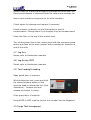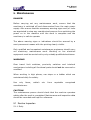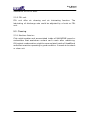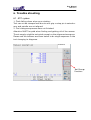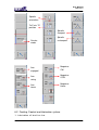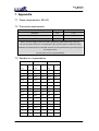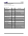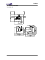
1
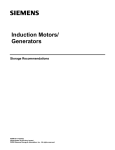
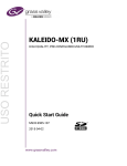
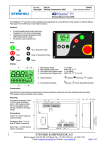
USER MANUAL
for
MRU Series
With Heidenhain Control
Revised: October 2013
User Manual
MRU Series
CONTENTS
1.
Safety.......................................................................................................5
1.1
Intended Use ..............................................................................5
1.2
Important Safety Notice and Warning .........................................5
1.2.1
Safe installation ...................................................................5
1.2.2
1.2.3
1.2.4
1.2.5
1.3
1.4
Safety Cautions List....................................................................7
Safety Devices..........................................................................10
1.4.1
Emergency Stop ................................................................10
1.4.2
Guard ................................................................................10
1.4.3
1.4.4
1.4.5
1.5
1.6
2.
Machine guarding................................................................6
Software ..............................................................................6
Authorized personnel and training.......................................6
Safe working practice ..........................................................6
Window .............................................................................10
Door Interlock ....................................................................10
Cabinet door lock and switch............................................. 11
Warning Labels......................................................................... 11
Residual Risks.......................................................................... 11
Introduction...........................................................................................13
2.1
Consumption Material...............................................................13
2.1.1
Lubrication oil for linear rail and ballscrew.........................13
2.1.2
Lubrication oil for pneumatic system .................................13
2.1.3
Cutting fluid .......................................................................13
2.1.4
Lubrication oil for rotary table ............................................13
2.2
Operation Panel........................................................................13
2.3
Spindle Tooling .........................................................................14
3.
2.4
2.5
Dimensions of work table..........................................................14
Tool Magazine and ATC............................................................14
2.6
Chip Removal ...........................................................................15
Installation.............................................................................................16
3.1
Foundation Preparation ............................................................16
3.2
Power Preparation....................................................................16
3.2.1
Line Configuration .............................................................16
3.3
3.4
3.5
Unpacking.................................................................................16
Machine Lifting .........................................................................17
Leveling of Machine..................................................................17
3.6
Before Power ON .....................................................................18
2
User Manual
MRU Series
3.6.1
3.6.2
Grounding..........................................................................18
Power connection..............................................................19
3.6.3
Misc. ..................................................................................20
3.7
First Time Power ON ................................................................20
3.7.1
Rotation Direction of Motors ..............................................21
3.7.2
Spindle Run-in ...................................................................21
4.
5.
Operation...............................................................................................22
4.1
Power ON/OFF.........................................................................22
4.2
Reference (or “ZERO RETURN” or “HOME”) the Machine ......22
4.3
Machine Warm-up ....................................................................22
4.4
4.5
4.6
4.7
Spindle Warm-up ......................................................................22
Interrupting Operation...............................................................22
Jobs Finished ...........................................................................22
Jog Axis ....................................................................................23
4.8
4.9
4.10
Jog Axis by MPG ......................................................................23
Tool Loading/Unloading ............................................................23
Large Tool management ...........................................................23
Maintenance ..........................................................................................25
5.1
Routine Inspection....................................................................25
5.1.1
Daily ..................................................................................25
5.1.2
Weekly (In addition to daily routine) ..................................26
5.1.3
Yearly (In addition to weekly routine).................................26
5.2
Lubrication................................................................................26
5.2.1
Automatic Lubrication System ...........................................26
5.2.2
FRL unit.............................................................................27
5.3
6.
Trouble shooting...................................................................................28
6.1
ATC system: .............................................................................28
6.2
Cooling, Coolant and lubrication system. .................................29
6.3
6.4
7.
Cleaning ...................................................................................27
5.3.1
Machine Interior:................................................................27
Door switch system ..................................................................30
Alarm messages and remedies ................................................30
Appendix ...............................................................................................31
7.1
Power requirements: 25 kVA ....................................................31
7.2
Pneumatic requirements...........................................................31
7.3
Spindle run-in procedures.........................................................31
7.4
Special M-function Codes.........................................................32
7.5
User Definable Parameters ......................................................33
3
User Manual
MRU Series
7.5.1
7.5.2
7.6
Parameters editing ............................................................33
Timer table.........................................................................33
Machine floor space .................................................................34
7.6.1
MRU-32 .............................................................................34
4
User Manual
MRU Series
1. Safety
1.1 Intended Use
This machine is a numerically controlled machine tool designed to
shape cold metal by the application of rotating cutting tools capable
of performing two or more machining processes (e.g. boring, drilling,
milling, thread tapping) at one set-up of a workpiece and
incorporating automatic facilities to:
Select and change tools from a magazine
Change the position of the workpiece relative to the spindle mounted
cutter.
Select and apply spindle speeds and axis feeds
Control ancillary services (e.g. coolant flow)
This machine is intended for use in an industrial environment and
must not be used in the residential, commercial and light industrial
environment.
Materials to be cut in this machine are: Steel, Iron, Iron casting,
Bronze, Brass, Copper, and Aluminium.
Materials not suitable to be cut in this machine are: Graphite, Wood,
Plastic, Magnesium alloy.
Consult the agent for the material not listed above.
1.2 Important Safety Notice and Warning
It is the user’s responsibility to be acquainted with the legal
obligations and requirements in the use and application of the
machine.
1.2.1 Safe installation
It is the customer’s responsibility to ensure the machine is installed
in a safe operating position, with all service pipes and cables clear of
the operation area so as not to cause a hazard. Access must be
allowed for safe maintenance, swarf and oil disposal including safe
stacking of machined and un-machined components.
5
User Manual
MRU Series
1.2.2 Machine guarding
This Machine is fitted with completely enclosed guards as standard.
In certain cases and tooling applications additional guarding may
have to be provided by the user.
The standard machine guarding has special safety interlocks on the
guard doors that comply with the Machinery Directive. Guards and
interlocks must be kept fully maintained and tested by the customer
and shall not be removed.
The guards are made with clear observation windows having high
impact resistance to provide operator safety and a clear
unobstructed view of the operations in process. The opening of any
guard door provides access to potential hazard areas. Opening of the
front working area guard doors is not allowed whilst the spindle is
rotating but it is still possible to manually initiate axis movements
whilst these doors are open albeit at a reduced traverse rate.
Extreme care must therefore be used at all times.
1.2.3 Software
Unauthorized changing of machines software or control parameters
is hazardous and is not permitted. The machine maker will not
accept any liability whatsoever for unauthorized changes in this
area.
1.2.4 Authorized personnel and training
Operating, service and maintenance engineers shall be authorized
by the ‘User Company’ and properly trained in the use of the
machine.
1.2.5 Safe working practice
Workholding devices, lifting equipment, tooling and their use shall be
the responsibility of the user. It is the user’s responsibility to protect
against the hazards caused by swarf, leaking oil or coolant and their
use.
Use of proprietary oil or coolant is the responsibility of the user.
Special instructions from the suppliers concerning their use should
6
User Manual
MRU Series
be carefully read and understood before use.
To prevent body injury, safe working practices should be employed
when operating or servicing the machine.
1.3 Safety Cautions List
It is the user’s responsibility to ensure all local regulations and safety
instructions are followed.
Users should consult with their own safety representative to ensure
that all such regulations are known and acted upon.
DON’T run the machine until you have made clear to your supervisor
that you understand the potential hazard of spindle rotation, the
throwing of coolant and the throwing of swarf from the cutting
process.
DON’T run the machine until you have read and understood all
manuals provided with the machine.
DON’T run the machine for the first time without a qualified
instructor. Ask your supervisor for help when you need it.
DON’T get caught in moving parts. Remove watches, rings,
jewellery, neckties and loose fitting clothes.
KEEP your hair away from moving parts.
PROTECT your eyes. Wear safety glasses with side shields at all
times.
PROTECT your head. Wear a safety helmet when working near
overhead hazards.
PROTECT your feet. Always wear safety shoes with steel toes and oil
resistant soles.
PROTECT your hands. Make sure the spindle is stopped before
manually changing a tool.
PROTECT your hands. Make sure the spindle is stopped before
manually changing a workpiece.
PROTECT your hands. Make sure the spindle is stopped before
manually clearing away swarf or oil. Use a brush or chip scraper.
NEVER use you hands.
PROTECT your hands. Make sure the spindle is stopped before
7
User Manual
MRU Series
manually adjusting the work piece or fixture or coolant nozzle.
PROTECT your hands. Make sure the spindle is stopped before you
take measurements.
PROTECT your hands. Make sure the spindle is stopped before you
move a safeguard. Never reach round a safeguard.
PROTECT your hands. Make sure the machine is switched off and
electrically isolated before making any mechanical adjustment.
PROTECT your hands. Beware sharp edges of cutting tools when
changing and handling tools.
PROTECT your eyes and the machine. Never use a compressed air
hose to remove swarf or to clean out air vents.
Gloves are easily caught in moving parts. TAKE THEM OFF before
you turns on the machine.
Loose objects can become flying projectiles. REMOVE all loose items
(wrenches, chuck keys, rags etc.) from the machine before starting.
PREVENT objects from flying loose. Securely clamp and locate the
work piece.
NEVER operate a machine tool after taking strong medication, using
non-prescription drugs, prescription drugs or consume alcohol which
may impair concentration.
ALWAYS make sure the working and cutting zone is safeguarded.
KEEP the work area well lighted. Ask for additional lighting if
needed.
DON’T slip. Keep your work area clean and dry. Remove swarf, oil
and obstacles.
NEVER lean on the machine. Stand away when machine is running.
DON’T get trapped. Avoid pinch points caused between other
machines and the machine you are working.
PREVENT cutter breakage. Use correct cutter speed and axis feed
rate for the job. Make manual over ride adjustments of axis feed rate
or spindle speed if you notice unusual noise or vibration. Ask your
supervisor for help if you need it.
PREVENT cutter breakage. Rotate the spindle in a clockwise
direction for right handed tools, counter clockwise for left handed
tools. Use the correct tool for the job.
8
User Manual
MRU Series
PREVENT work piece and cutter damage. Never start the machine
when the cutter is in contact with the work piece.
Dull and damaged tools break easily. Inspect tools and tool holders.
Keep tools sharp. Keep overhang short.
KEEP all lubrication reservoirs maintained at the correct level.
Always keep to the maintenance schedule.
Certain materials such as magnesium are highly flammable in dust
and chip form. See your supervisor before working these materials.
PREVENT fire. Keep flammable liquids and materials away from the
work area and from hot swarf.
PREVENT the machine from moving unexpectedly. When leaving
the machine unattended, not producing, leave switched in the
MANUAL mode.
DON’T use the machine in a volatile atmosphere. Electrical devices
fitted to the machine are for normal factory use and are not
explosion proof.
ALWAYS keep the machine clean and do not let swarf collect.
ALWAYS keep the area around the machine clean and tidy. Opening
the guards creates the potential for residual coolant and swarf to fall
to the swarf tray and possibly to the floor. Good housekeeping
minimizes the potential for trips, slip or fall of all personnel.
INFORM all other personnel who approach the machine about the
hazards described in this safety list.
When making adjustments with spanners, always ensure that the
required leverage is safely applied. Always avoid slippage. Always
apply the leverage by pulling, never by pushing. Always use the
correct size spanner. Ensure the spanner is not damaged.
Do not use organic chemical solvents to clean the machine guards or
compressed air services equipment.
The windows are manufactured from bulletproof polycarbonate
sheet. This material does deteriorate with age, and should be
exchanged within the time period described later in this manual.
Any workholding device used in conjunction with this machining
centre must fit within the working envelope available. Under no
circumstances must any such workholding device be used when it
would require the need to override/defeat the safety interlocks fitted
9
User Manual
MRU Series
as standard to this machine.
1.4 Safety Devices
1.4.1 Emergency Stop
Make yourself aware of the location of the emergency stop push
buttons, which should be well known so that they can be operated at
any time without the need to look for them. Test the push buttons
periodically for their correct operation.
The emergency stop push buttons is located on the operator panel.
Once the Emergency Stop button is pressed or any of the over travel
limit switches have been operated, the machine will stop
immediately and the power supply to the drives is removed, and go
into an Emergency Stop condition
1.4.2 Guard
Machine equipped front door, ATC door, side door and full guard as
safety device to protect operator. Doors are not allowed open in any
time when machining.
1.4.3 Window
Machine equipped with 9.5 mm thickness PC safety glass on front
and side guard. The window impact resistance capacity is at 821.8
kg.m. Any crack on the window is not allowable.
1.4.4 Door Interlock
The machine has 1 interlocked main access door at the front. The
main door is shot bolted shut and can only be opened once the
spindle is stationary and there is no program running.
Power On Safety Circuit (Allows the operator to execute certain
tasks whilst the front door is open)
Limited machine functionality is available to the operator whilst the
main door is open. The handwheel and jog keys are allowed to move
the machine axes at feed rates of 1260mm/min and less. Spindle
10
User Manual
MRU Series
operation is prohibited whilst the main door is open as the spindle
contactor is hard wired through the door interlock switch. Selection
of automatic program running is prohibited until the doors are shut.
1.4.5 Cabinet door lock and switch
The main power switch of machine must be shut
off and turned further CCW to open the cabinet
door.
1.5 Warning Labels
Most of the warning labels are self-explained as
following:
1.6 Residual Risks
The machine tool has been designed and manufactured to the
highest standards, but still, your attention is drawn to the following
RESIDUAL RISKS existing within the machine.
Always check that the cutting tool product you are using is
approved to run at the selected speed.
If non suitable cutting conditions are selected, coolant can
11
User Manual
MRU Series
splash, and swarf can escape over the sides of the guard.
Failure of the Z-axis servo motor brake could allow the head to
fall when the power is OFF
Do not operate the machine with the side door access panels
removed.
Isolate the machine before cleaning the machine through the
side door access panels
12
User Manual
MRU Series
2. Introduction
2.1 Consumption Material
2.1.1 Lubrication oil for linear rail and ballscrew
Lubrication oil for linear rail and ballscrew are as follow:
Qt’y
Recommended oil
4 liter
FEBIS K68 (ESSO)
VACTRA NO.2 (MOBIL)
TONNA OIL T68 (SHELL)
2.1.2 Lubrication oil for pneumatic system
Oil for pneumatic system is recommended to use same specification
of ESSO TERESSO 32 or SHELL TELLUS OIL 32. Total quantity oil for
machine in every half year need 120 cc.
2.1.3 Cutting fluid
Cutting fluid and mixing ratio with water are recommended by
following table. Coolant tank capacity is 160 liter.
Marker: Castrol
No.
Type
Application
Dilution ratio
with water
1
SYNTIOL-9913
Aluminum cutting only
1:15
2
ALUSBL-B
Aluminum cutting only
1:15
3
HYSOL-X
Various material cutting
1:20
2.1.4 Lubrication oil for rotary table
Lubrication oil with viscosity ISO-VG100 to 150.
2.2 Operation Panel
Please refer to Heidenhain manuals.
13
User Manual
MRU Series
2.3 Spindle Tooling
Tooling with a balance level of G2.5 or better should always be used.
Failure to do so will reduce spindle life and surface finish and may
invalidate the machine warranty.
For safe operation, make sure the tool holder and pull stud
combination meet the standard below:
BT-40
DIN-40 (CAT-40)
2.4 Dimensions of work table
2.5 Tool Magazine and ATC
14
User Manual
MRU Series
Tools magazine
ATC cam box
Tool Change Arm
2.6 Chip Removal
Chips were washed away from the interior of machine and flow into
the chute where the chip screw augers or chip conveyor located.
Then chips were collected at the exit of screw auger or conveyor.
15
User Manual
MRU Series
3. Installation
3.1 Foundation Preparation
The machine should be sited on a flat area (maximum fall 3mm in 3
m) free from cracks and expansion joints.
The composition of the floor and sub-structure should be of suitable
construction to bear the weight of the machine. Any friable areas
should be made good using recognized building construction
techniques. If doubt exists we recommend you consult your building
architect.
3.2 Power Preparation
3.2.1 Line Configuration
The machine is designed to operate from a
3-phase AC incoming power source with an
earth star point, as shown in the right. This
incoming line short circuit current must be
at least 2kA.
In other cases, such as those examples shown in figures below, an
isolating transformer of 15kVA or larger capacity with an earth
grounded WYE secondary is required between the incoming lines and
the machine. The incoming line short circuit current must again be
least 2kA.
Other Incoming Line Configurations
3.3 Unpacking
16
User Manual
MRU Series
The machine was fixed on a skid during which could be pulled to the
opening of container and then moved by a fork lifter.
Select a chain according to the weight of the machine. Tie the chain
to the skid and make sure the connection is secured. Slowly pull the
machine and monitor the gap between the machine and the wall of
the container.
3.4 Machine Lifting
Any lifting cables and slings must be rated to take the machine’s
weight.
If the machine is to be lifted by Fork Truck, the minimum capacity
should be 120% of the machine weight and with a minimum tine
length of 2,000mm.
3.5 Leveling of Machine
a) Make sure the location of the machine is exactly where you need
it to be. Ensure allowance for access for operation, cleaning and
maintenance is provided. See the installation dimensional
drawing for minimum clearances.
b) Locate the floor pads which are packed with the associate kit and
position them on the floor under each jack bolt. When satisfied
17
User Manual
MRU Series
lower the machine gently onto the pre-located pads. Ensure jack
bolts are screwed down to provide a 10 to 15mm gap from the
underside of the base casting to the floor.
c) If you use skates then employ the jack bolts with suitable support
packing to raise the machine enough to remove the skates and
finally set onto the floor pads.
3.6 Before Power ON
3.6.1 Grounding
a)
The machine must be grounded in order to protect personnel
and the machine from electrical hazards. Grounding must be in
accordance with the standards for electrical equipment.
b)
Ideally, the grounding point should be as close as possible to the
machine.
c)
A qualified electrician must carry out the grounding work,
otherwise serious injury, death, or accidents involving machine
damage could result.
d)
The machine must be grounded in one of the following ways:
1) Independent grounding
2) Common grounding
Regardless of the type of grounding system used, the earth loop
impedance of the supply, which connects the machine to
ground/earth, must not exceed 1 ohm.
e) Never ground the machine in the manner shown in the
illustration below.
18
User Manual
MRU Series
No more than one grounding conductor wire can be connected to a
single terminal. If the grounding conductors are connected in the
manner shown in the illustration above, a faulty connection at one of
the terminals could cause grounding current to be fed back to the
machine, resulting in serious accidents.
Once the electrical and air supplies are provided make the
connection to the machine. The delivery dimensional drawing gives
details of input locations.
ON NO ACCOUNT MUST YOU SWITCH ON THE MACHINE.
WE PREFER YOU TO REMOVE YOUR ISOLATOR FUSES OR TRIP
CIRCUIT BREAKERS.
3.6.2 Power connection
A qualified electrician should only carry out connection of the power
lead to the machine.
Cables, cords or electric wires of which insulation is damaged can
produce current leaks and electric shocks. Check their condition
before connecting.
Ensure the power cable to the machine main isolator has sufficient
current carrying capacity to handle the electric power used.
Cables which must be laid on the floor, must be protected against
chips, oil and coolants penetration, which might cause damage.
In the event of power failure, turn off the main circuit breaker
19
User Manual
MRU Series
immediately.
Fuses and circuit breakers should be replaced only with suitably
rated alternatives. Safety devices should be replaced only with the
machine manufacturers recommended parts.
Protect the CNC unit, operating panel, and electric cabinet etc from
shocks which could cause a failure of malfunction.
Connect the power cable to main
power terminal block. Ensure the
sign rotation of R, S, T phases.
Connect the ground cable to the
Earth bar.
3.6.3 Misc.
Check the condition of the warning labels. If they are missing or
become illegible, order replacements from your distributor according
to the part number on the label plate. Do not remove warning labels.
After unpacking the machine clean all rust preventatives from the
machine with a non-volatile cleaning fluid. Lightly lubricate each
sliding part before trying to operate the machine. Manually operate
the lubricating oil pump until oil oozes out from the slide way wipers.
Oil volume should be filled to the indicated level. Check and top up if
necessary.
Use recommended oil brands and appropriate levels for all
lubricating systems. See the instruction plate at the rear of the
machine.
The coolant system comprises of a separate tank which houses the
coolant pumps and is located beneath the front and left sides of the
machine.
3.7 First Time Power ON
20
User Manual
MRU Series
3.7.1 Rotation Direction of Motors
The rotation of 3-phase motors of pumps, chips removal and fans
might be reversed due to the different phase sequence of city power
U, V and W. Please confirm the rotation of all the coolant pumps and
cooling fans.
3.7.2 Spindle Run-in
The grease inside the bearings of spindle might be concentrated by
gravity due to temperature variation during the transportation and
storage. It is a MUST to run the spindle following the procedures
described in Appendix.
21
User Manual
MRU Series
4. Operation
4.1 Power ON/OFF
Please refer to Heidenhain manuals.
4.2 Reference (or “ZERO RETURN” or “HOME”) the Machine
Usually this is not needed since this machine is with absolute axis
encoders. Please refer to Heidenhain manuals, if you do need to do.
4.3 Machine Warm-up
** If the machine is used to produce components immediately after
being started, following a long idle period, sliding parts may be worn
due to lack of oil and thermal expansion of the machine can
jeopardize machining accuracy. To prevent this condition, always
warm the machine up. **
We recommend that the machine is ‘Warmed up’ prior to operation
by running all axes for 20 minutes at the speed of actual cutting in
the automatic operation mode. The spindle speed should be
gradually increased up to actual cutting speed.
4.4 Spindle Warm-up
If the following procedures are not followed, spindle life will be
reduced significantly. Follow the speed and running time duration in
the table for each type of spindle. Please note that the duration is
either in minutes (m) or in seconds (s).
4.5 Interrupting Operation
When leaving the machine temporarily after completing
a job, turn off the power on the operator panel with the
Emergency Stop button and turn off the main isolator.
4.6 Jobs Finished
22
User Manual
MRU Series
Always clean the machine and supporting equipment down after use.
Remove and dispose of chips and clean the covers and windows etc.
Return each machine component to its initial condition.
Check wipers for damage and replace if necessary.
Check coolants, hydraulic oils and lubricants for level &
contamination. Change them if you suspect they are contaminated.
Clean the filter on the top of the coolant tank.
Turn off the power first on the control panel with the emergency stop
button and then at the main isolator before leaving the machine at
end of the shift.
4.7 Jog Axis
Please refer to Heidenhain manuals.
4.8 Jog Axis by MPG
Please refer to Heidenhain manuals.
4.9 Tool Loading/Unloading
Open guard door of machine.
While holding the tool, press and hold
the clamp/unclamp button on the
machine head to release the tool (See
illustration). Replace tool and
release the button to clamp.
Close guard door of machine.
Using AUTO or MDI, load the correct tool number into the Magazine.
4.10 Large Tool management
23
User Manual
MRU Series
Please refer to Heidenhain manuals.
24
User Manual
MRU Series
5. Maintenance
DANGER!
Before carrying out any maintenance work, ensure that the
machinery is switched off and disconnected from the main power
supply. Also ensure that the necessary warning signs and /or locks
are appointed to stop any unauthorized persons from switching the
power on to the machine until the work is complete and the
machinery is safe to operate.
The above warning signs or indications should be secured by a
semi-permanent means with the printing clearly visible.
Only qualified and competent maintenance engineers should carry
out machinery maintenance work. Working on live electrical
equipment must be carried out by only suitably qualified electricians.
WARNING!
Over travel limit switches, proximity switches and interlock
mechanisms including all functional parts should not be removed or
modified.
When working in high places, use steps or a ladder which are
maintained daily for safety.
Use only fuses,
manufacturers.
cable's
etc.
from
reputable
recognized
CAUTION!
The maintenance person should check that the machine operates
safety after the work is completed. Maintenance and inspection data
should be recorded and kept for reference.
5.1 Routine Inspection
5.1.1 Daily
25
User Manual
MRU Series
1. Check pressure gauges for proper reading. Air pressure
5.5bar (80psi). Hydraulic pressure 68bar (986psi)
2. Check that there is sufficient oil in the air lubricator.
3. Check motors and other parts for abnormal noises.
4. Check the lubrication of sliding parts for evidence of proper
lubrication.
5. Check safety covers and safety devices for proper operation.
6. Check coolant level and fill as necessary.
7. Clean dirt and chips from the axes and empty the swarf trays.
5.1.2 Weekly (In addition to daily routine)
1. Clean chips and dirt from the entire machine and wipe down.
2. Check the air filter at the rear of the electrical cabinet. Replace
the filter element if it is contaminated.
3. Check all polycarbonate vision panels for signs of damage –
crazing, cracking etc. or reduced visibility and replace if
necessary. Contact your distributor for details.
4. Check the spindle cooler/chiller is running properly and the
coolant temperature is near the temperature setting.
5. Check the spindle front draining hole from labyrinth is not
jammed by dirt.
6. Check the air purging at the spindle nose. Run the spindle for
10 seconds and stop. Listen or feel the air flowing from the
gap between the spindle shaft and housing.
5.1.3 Yearly (In addition to weekly routine)
1. Remove the filter from the air filter bottle and clean/replace.
2. Check spindle drive belt condition and tension.
3. Check lost motion.
4. Check the condition of the linear rail wipers.
5. Check the integrity of the electrical connections and inspect
the condition of the insulation.
6. Check condition of coolant filters and replace if necessary.
7. Replace the lubrication oil in rotary table once a year.
5.2 Lubrication
5.2.1 Automatic Lubrication System
Lubricator supply 1cc oil to lubricate ballscrew once time every 15
minutes. Oil discharge volume can be adjusted by a handle and
26
User Manual
MRU Series
illustration on the oil tank.
5.2.2 FRL unit
FRL unit offer air cleaning and air lubricating function. The
lubricating oil discharge rate could be adjusted by a knob on FRL
unit.
5.3 Cleaning
5.3.1 Machine Interior:
Chip might spatter and accumulated inside of MAGAZINE guard or
somewhere that washdown coolant can’t reach after machining.
Oil/coolant condensation might be accumulated inside of HeadStock
and effect machine operating in good condition. It needs to be check
or clean out.
27
User Manual
MRU Series
6. Trouble shooting
6.1 ATC system:
1. Tools falling down when arm rotating:
Tool can not be clamped well due to arm grip or stop pin is seized or
arm and spindle are not aligned.
2. Tool change sequences were not finished:
Attention MUST be paid when finding and getting rid of the causes.
The air supply might be not quick enough or the alignment was gone.
Please use the buttons as shown below to do single sequence in the
tool changing to diagnose.
Tool Change
Functions
28
User Manual
MRU Series
Spindle
orientation
To Z axis TC
position
Spindle
clamped
Spindle
unclamped
Service
mode
Magazine
CW
Arm
engaged
Magazine
CCW
Arm
swing
Magazine
Home
Arm
home
6.2 Cooling, Coolant and lubrication system.
1. Lubrication oil level too low
29
User Manual
MRU Series
Refill lubrication oil into tank
2. Lubrication pressure too low
Refill lubrication oil or replace whole lubricator unit.
3. Coolant pumps noise.
Pump sealing is break down or chip materials invade into pump.
6.3 Door switch system
1. Front door is opened
Close front door or replace interlock switch
6.4 Alarm messages and remedies
Please refer to Heidenhain manuals for the alarm messages except:
Alarm No.
Alarm Message
Cause
Remedy
260
CTS filter pressure
high
Filter was dirty and
jammed.
Pressure switch bad
Check filter and replaced if it is
dirty.
Check the pressure switch and
replaced if it is bad.
261
Oil cooler malfunction
Oil cooler not function
normally.
Check the alarm code at the
display of oil cooler and refer to
the manual of oil cooler.
30
User Manual
MRU Series
7. Appendix
7.1 Power requirements: 25 kVA
7.2 Pneumatic requirements
Unit
Value
Pressure
bar
> 5.5
Flow rate
Litre/min
> 400
Dew point (at ATM. Pressure)
°C
-17 or lower
Note: The air supply must be clean (40micron particulate size) and dry.
Do not connect direct to a compressor with a short pipe as water/oil may
condense out and cause a potential seizure of the spindle bearings through the
air purge circuit.
An air drier unit is recommended.
7.3 Spindle run-in procedures
12000 rpm
Speed
10000 rpm
Time
(rpm)
Speed
8000 rpm
Time
(rpm)
Speed
Time
(rpm)
1000
5m
1000
5m
1000
5m
5000
3s
5000
3s
5000
3s
2000
5m
2000
5m
2000
5m
10000
3s
10000
3s
9000
3s
3000
5m
3000
5m
3000
5m
12000
3s
--
--
--
--
4000
5m
4000
5m
4000
5m
5000
5m
5000
5m
5000
5m
6000
5m
6000
5m
6000
5m
7000
5m
7000
5m
7000
5m
8000
5m
8000
5m
8000
5m
9000
5m
9000
5m
10000
5m
10000
5m
11000
15 m
12000
15 m
31
User Manual
MRU Series
7.4 Special M-function Codes
Function Description
M21 External air ON
M22 External air OFF
M23 Wash down ON
M24 Wash down OFF
M931 Renishaw tool break
M932 Renishaw latch
M933 Renishaw reset nci 4
M934 TT air ON
M935 TT air OFF
32
User Manual
MRU Series
7.5 User Definable Parameters
7.5.1 Parameters editing
Please refer to Heidenhain manuals.
7.5.2 Timer table
Timer variables
DATA
seconds
/ts:TS_key_pulse_recognition
0.5
/ts:TS_pulse_250_ms
0.25
/ts:TS_gear_timeout
30
DISCRIPTION
Time allowed before timeout alarm of gear
change
/ts:TS_gear_rotation_cw
0.35
Time of CW at gear change
/ts:TS_gear_rotation_ccw
0.15
Time of CCW at gear change
/ts:TS_gear_rotation_pause
0
Time pause after gear change
/ts:TS_lubrication
5
Time duration after lubrication pressure built
/ts:TS_lubricant_pressure
15
Time waiting for lubrication pressure to build
/ts:TS_hydraulic_pressure_ok
10
/ts:TS_start_index_table
1
Time
delay
before
checking
hydraulic
pressure
/ts:TS_Timer_1_min
1.5
/ts:TS_extern_DC_voltage_on_off
1.5
Time duration to turn OFF the DC voltage
/ts:TS_extern_DC_voltage_off_on
1.5
Time duration to turn ON the DC voltage
/ts:TS_TCM_exact_position
0.3
/ts:TS_TCM_timeout
120
/ts:TS_TCM_stop_delay
Time allowed before timeout alarm of tool
change
0
/ts:TS_TC_timeout
120
/ts:TS_TC_timer_universal
0.25
/ts:TS_TC_arm_middle_delay
0.25
/ts:TS_TSxxx_blow_off
0
Time for blow OFF of TSxxx
/ts:TS_S1_blow_after_CTS_off
3
Time of blow ON after CTS OFF
/ts: TS_gear_output_delay_on
1
Time delay of gear change output ON
/ts:TS_gear_output_delay_off
0.5
Time delay of gear change output OFF
33
User Manual
MRU Series
7.6 Machine floor space
7.6.1 MRU-32
34