1
A+ SERVER 1042G-TF User's Manual
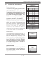
Power Fail LED
PWR Fail LED
Pin Definitions
(JF1)
The Power Fail LED connection is located on
pins 5 and 6 of JF1. Refer to the table on the
right for pin definitions.
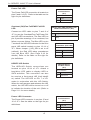
Overheat (OH)/Fan Fail/PWR Fail/UID
LED
Connect an LED cable to pins 7 and 8 of
JF1 to use the Overheat/Fan Fail/Power Fail
and UID LED connections. The Red LED on
pin 8 provides warnings of an overheat, fan
failure or power failure. The Blue LED on pin
7 works as the UID LED indicator for the front
panel UID switch located on pins 13~14 of
JF1. When Jumper J_UID_OW is set to off
(default), the Red LED takes precedence
over the Blue LED. (See Page 2-19 for
details.) Refer to the table on the right for
pin definitions.
HDD/FP UID Switch
The HDD/UID Switch connections are
located on pins 13/14 of JF1. Attach a
hard-drive LED cable to display HDD or
SATA activities. This connection can also
be used as a front panel UID (Unit Identifi
er) switch. The UID LED on Pin 7 of JF1
works in conjunction with this UID Switch.
When the user presses and releases the UID
switch, the UID LED will be turned on or off
to indicate the location of the unit. (Refer to
Page 2-11 for more details.)
Pin# Definition
5
3.3V
6
PWR Fail LED
OH/Fan Fail/ PWR Fail/Blue_UID
LEDPin Defi nitions (JF1)
Pin# Definition
7
Blue_LED-Cathode(UID)/5.5V.SB
8
OH/Fan Fail/PWR Fail/UID LED
(Red)
OH/Fan Fail/PWR Fail
LED Status (Red LED)
State
Normal
On
Overheat
Flashing
Fan Fail
HDD/UID Switch
Pin Defi nitions
(JF1)
Pin# Definition
13
UID Signal/3.3V
14
HDD Active
Power LED Connector
The Power LED connector is on pins 15 and
16 of JF1. See the table on the right for pin
definitions.
A
Indication
Off
Power LED
Pin Definitions
(JF1)
Pin# Definition
15
PW_ON
16
Ground