1
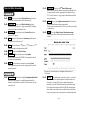
INSTALLATION GUIDE
NuS Module
[ CM4200 ]
INSTALLATION GUIDE
CM4200
www.NUSTART.ca
TABLE OF CONTENTS
Page 2
-
Wiring Diagram
Page 4
-
Notes for Wire Connection
Page 6
-
Switch and Jumper Setting
Page 12
-
Installation of Antennas
Page 12
-
Option Programming for Four Button Remotes for FM or SS Units
Page 13
-
Installation of AM Antennas
Page 14
-
Option Programming with Programming Button for AM Units
Page 14
-
Option Programming for Six Button Remotes
Page 16
-
Programming Menu Options
Page 16
-
Diagnosing Problems with Auto-Start
Page 19
Page 3
Wiring Diagram
Page 4
Page 5
Notes for Wire Connection
Pin #1 : Red This wire is used as the (+)Constant Power input for the unit.
This wire must be connected for the unit to function correctly.
Pin #2 : Green/ White This wire is the (+)Positive Parking light output.
Connect this wire directly to the (+) trigger wire generally off the parking
light switch or found at or behind the fuse box.
Pin #3 : Red/ White This wire is used as the (+)Constant Power input for
Starter and 2nd Ignition.
Pin #2 : Red/ Black This wire is a (-) 2 nd Starter 200mA output.
Normally the only vehicle this would be used on Nissan’s and older Ford’s.
You may connect this wire to the purple pigtail of the additional relay on
CN #1. This will result in a (+) trigger output for the 2nd starter on the blue
wire of the same relay.
Pin #3 : Violet This wire is the (-) Negative when armed out . It will provide a
(-) output anytime the unit is armed or remote started.
This wire is pre-wired into the starter-kill. This wire could be used for adding
a window roll-up.
Pin #4 : Black This is the (-)Status Out wire (Ground when running).
It provides you with a (-) 200mA output as soon as the remote start is
activated.
Pin #4 : White This wire is used to power the ( +)Accessory, which activates
the blower motor for the heater or A/C.
Pin #5 : Blue This wire will power (+)2nd Starter, (+) 2nd Accessory or (+) 2 nd
Ignition depending on the jumper selection at JM1.
Pin #6 : Yellow This wire is the (+) Starter Output.
Pin #7: Green/ Red This wire is used to power the (+) Ignition.
This wire is also an input for the NUSTART used to monitor the status of
the vehicle and for programming.
Pin #8 : Black This wire needs to be connected to a chassis (-)Ground.
It is very important to make sure you have a good ground or the unit will
not function correctly.
This is the wire you would connect to a Transponder Module or maybe a
VATS module.
Pin #1 : Green/ White This is the low voltage (-) Parking light output 200mA.
Some newer vehicles require a (-) parking light output instead of the
standard (+) output (reference connector #1) such as the new Jeeps and
even some Fords.
Page 6
Pin #5 : Orange This is the Rearm wire. It provides you with a ( - ) pulse when
armed, after remote start, and then again one second after remote start
shuts down. As of August 2004, this wire’s output duration has been
increased by 1.0 second. This has been done to provide the Dome Light
Factory Rearm feature currently offered in the CM3000 controller module.
Some vehicles require the door to be open while the door is locked for the
factory security system to arm. Connecting this wire to the dome light circuit
Page 7
(generally you will have to change the polarity with a relay) will simulate the door
opening 0.5 seconds before the lock pulse, and will keep the simulated door open
until 0.5 seconds after the lock pulse has ended.
Pin #6 : Orange/White This is the Disarm wire. It provides you with a
(-) pulse when disarmed and before remote start.
Pin #4 : Violet/ Black This wire is the (-) trigger input, which may be
connected to a trunk pin or trunk trigger as a buyer option.
Pin #5 : Red/White This wire is the (-) trigger input for the door trigger. You
would connect this to the trigger that shows (-) when the door is opened.
Pin #6 : Red This wire is the (+) input for the door trigger. You would
connect this to the trigger that shows (+) when the door is opened.
Pin #7 : Brown /Black This is the trigger input for a (-) glow plug wire .
Pin #8 : Brown /White This is the trigger input for a (+) glow plug wire.
Pin #9 : Yellow/ Black This wire serves as the Tachometer input or the
Alternator input. Either way you use it, it is for engine sensing.
This wire tells the NUSTART when to quit cranking the starter of the vehicle.
There are a couple of ways to find the correct voltage for either type of
sensing. Please review the following tips on the next page.
- Tachometer
Pin #7 : White This is the (-) 250mA horn honk output wire.
Pin #1 : Light Blue This needs to be connected to the parking brake.
This wire requires a (-) input to activate. This wire serves two functions:
1. To engage Reservation Mode for manual transmissions, reference
the users or install guide.
2. To activate the Turbo Timer, reference the users or install guide.
Pin #2 : Gray/ Black This is the (-) shutdown for the Hood Trigger.
This wire serves two functions:
1. It prevents the remote start from activating while the hood is open
2. It will trigger a full alarm if the hood is opened when the alarm has
been armed.
Pin #3 : Light Blue/ White This is the (+) shutdown for the foot brake.
This wire will shut down the remote start if the foot brake is pressed.
Page 8
Sensing
1. You will need an Auto Ranging Digital Meter to test for the correct tach.
2. Most tach wires are located at the (-) side of the ignition coil. In some cases
you may have to go to the ECU or Coil pack.
3. The Voltage will read (AC), so you will need to set you meter accordingly.
4. With the vehicle off the voltage should read 0.00 AC.
5. Start the vehicle and at this time the voltage should fluctuate between 1 and 8 volts A C.
6. Connect the tachometer wire to the yellow/black.
7. Make sure that the Dipswitch #1 is set to the On position.
8. While the vehicle is running press the small black button on the side of the brain,
Parking Light will flash once if you have the correct Tach wire.
9. If the cars parking lights flash 3 times, there is a problem with the tachometer
learning. Wait for 2 seconds and the cause for the error will be indicated by the
number of times the parking lights flash.
10. Diagnosing Tach Learning Error
If the cars parking lights flash 3 times, there is a problem with the
tachometer learning. Wait for 2 seconds and the cause for the error
will be indicated by the number of times the parking lights flash.
Page 9
Error Number
(# of times parking lights flash)
Please note that this feature requires more advanced installation.
Please call Technical Support for details.
Tach Learning Error Diagnosis
1
Dip Switch #1 is on alternator sensing.
2
Manual Car Key is in the off position.
3
No signal or the signal is not fast
enough. find a different wire.
Pin #4 : Blue This wire is a (-) 200mA Unlock Output .
Pin #5 : Blue/Black This wire is a (-) 200mA Lock Output.
Pin #6 : No Conncetion
- Alternator Sensing
1. Just like with Tachometer sensing you will need a Auto Ranging Digital Meter
to test for the correct wire.
2. Set your meter to DC voltage for this type of sensing, compared to AC voltage
for the Tach sensing.
3. To find this wire you will need to locate the alternator. Look for the Stator wire,
Which is always located somewhere on the alternator. It will usually be a
smaller gauge wire and generally by itself.
4. With the vehicle in the OFF position the voltage should read 0.00
5. Turn the key to Ignition and the voltage should read anywhere from 1 to 6 volts DC.
6. Next, start the vehicle. The voltage should now read between 9 to 14 volts DC.
7. If this is the case you have found the Alternator wire, connect this to the
Yellow/Black on CN 3
8. Set dipswitch #1 to the OFF position. Please note, you will not need to press the
small black button on the side of the brain, it is automatic.
Pin #1 : No Connection
Pin #2 : Violet/ White This wire is the (-) 200mA trunk release.
The following sequence takes place each time the trunk release output
is triggered :
1. NUSTART disarms alarm and unlocks doors
2. Trunk output is triggered
Pin #3 : Orange/Black This wire provides you with the capability of adding
driver’s door priority unlock similar to factory keyless entry systems.
Page 10
This is the plug in for temperature sensor input. This sensor will monitor the internal
temperature of the vehicle and be programmable for timed engine starts.
This is the plug for the antenna cable.
The is the data lines to interface Telematic Devices or Interface Modules.
-
Tach Learning Switch :
This is the small black button on the side of the brain used to program tach. Once
you have found the correct wire simply press this button while the vehicle is running
and the parking light will flash once to confirm that the tach is learned. If the parking
light flash three times the tach source is not valid.
Pin #5 wire of CN1 will power the (+)2 nd Starter, (+) 2nd Accessory or (+) 2nd
Ignition depending on the jumper selection at JM1.
Switch #1: This is used to set either Tach or Alternator mode. If the switch is
set to the ON position the unit is set to Tach. If the switch is set to the OFF position
then the unit is set for Alternator sensing.
Page 11
: This is used for setting run time. If the switch is set to the OFF
position then the run time is set for 15 min for gas engines or 25 min for diesel
engines. If set to the ON position then the run time is set to 25 min for gas engines
or 45 min for diesel engines.
Jumper Wire : This jumper is connected when you receive the brain.
Switch #2
While the jumper is connected the module is set for manual transmission mode.
When installing on automatic transmissions the jumper must be cut. Please note :
if a unit with a cut jumper is installed on a manual transmission the warranty will
be void and Staub Electronics will have no liability.
Dip
Switch
Jumper Wire
#1
#2
On
Uncut: Manual Transmission
Tach Sensing
25 min run time (45 min diesel)
Off
Cut: Automatic Transmission Alternator Sensing 15 min run time (25 min diesel)
Once you cut the jumper wire, you are not allowed to reconnect it.
Reconnection will completely void the warranty. A trace of reconnection of this wire will
prevent you from making any claim whatsoever pertaining to the manual transmission mode.
Installation of Antennas
The antennas have been calibrated for
horizontal installation at the left-top corner
of the windshield. Different installation
may adversely affect the transmitting
distance.
Page 12
Step1: For Programming menu 1: Press Buttons (I+II) for 2 seconds.
For Programming menu 2: Press Buttons (I+IV) for 2 seconds.
The car will chirp once indicating that you are in programming mode.
Step2: Wit hin a 2 seconds after pressing (I+II) or (I+IV), press Button IV
the number of times to go to the option number you want to change.
You have to hear a chirp and see the parking light flash
each time when you press Button IV.
Step3 : Wait a few seconds. You will hear a number of chirps and see a
Switch and Jumper Setting
Important!
Option Programming for Four Button Remotes for FM or SS Units
number of parking light flashes corresponding to the option number
you want to change. If the number of chirps or flashes is not what
you want, go back to Step 1.
Step4 : Press Button I for the default factory settings and your car will
respond by one chirp and one flash. Press Button II for the optional
setting and your car will respond by two chirps and two parking flashes.
-
-
If you see an extended flash of the lights, you are going out of
programming mode, please go back to Step 1.
If you want to change more options, go back to Step 1.
- Resetting any Option Setting to the Factory Setting
Step 1: Press Buttons (I+II) simultaneously or Buttons (I+IV) simultaneously
for 2 seconds. A one flash of the parking lights confirms step 1.
Step2 : Press Button III three times. This is confirmed by a parking light flash
each time you press Button III. A few second later, your cars parking
lights will flash three times rapidly. Your car is now set to all of the
original factory default settings.
Page 13
Installation of AM Antennas
Step 3: Within 4 seconds after you released the switch, press and release
PS for the number of times of the option number you want to change.
The antennas have been calibrated for
horizontal installation at the left-top corner
of the windshield. Different installation
may adversely affect the transmitting
distance.
Step 4: Within 2 seconds, the LED and Parking Lights will flash the same
number of times as you pressed the switch at step 3.
Note : If the number of flash does not correspond to what you did at Step 3,
1) wait for 4 seconds until Parking Light flash once for 1 second to
reset. If this happens, go to Step 2, or
2) turn the key off and go to the Step1.
Step 5: Within 4 seconds from step 4, press PS once for factory setting, the LED
and Parking Lights will flash once to confirm. Press PS twice for optional
setting, the LED and Parking Lights will flash twice to confirm.
Option Programming with Programming Button for AM Units
CANADIAN MODELS ONLY. THE US MODELS DO NOT HAVE THE BUTTON.
Most of the original programming (“Factory Setting”) from the factory can be
changed to alternative programming (“Option Setting”) by Programming Switch
(hereinafter called “PS”).
Step 6: If you want to change more options, go to Step 3. However, if you
want to change options from Option#1-1 to #1-11 to Option#2-1 to
#2-10 or vice versa,
1) wait for 4 seconds until Parking Light flash once for 1 second to reset.
Then go to the Step 2, or
2) turn the key off and go to the Step 1.
- Resetting any Option Setting to the Factory Setting
If you want to reset any changes you made to the Factory Setting,
Step 1: Turn the key to On position. (Engine Off)
LED
Programming Button
LED flashes when locked or the passive
starter-kill is activated.
- Changing Factory Setting to Option Setting. #1
Step 1: Turn the key to On position. (Engine Off)
Step 2: Press PS (Programming Switch) for two seconds until Parking Light
flashes once for Option #1-1 to #1-11, then release the switch.
Or, press PS for four seconds until Parking Light flashes twice for
Option #2-1 to 2-10, then release the switch.
Page 14
Step 2: Press PS (Programming Switch) for two seconds until Parking Light
flashes once for Option#1-1 to #1-11, then release the switch.
Or, press PS for four seconds until Parking Light flashes twice for
Option#2-1 to #2-10, then release the switch.
Step3: Within 4 seconds after you released the switch, press and release
PS for 3 seconds.
Step4: Within 2 seconds, the LED and Parking Lights will flash three times
to confirm the above step. If any of the above steps is not followed
correctly, the Parking Lights will flash once for 1 second to reset.
If that happens, please start from Step 2.
Page 15
Note :
Option Programming for Six Button Remotes
The procedures will be same as the 4 button remotes except the use
of the different buttons.
Programming
6 Button Remote 4 Button Remote
Programming Menu 1
Programming Menu 2
Option Selection
Factory Setting
Option Selection
Default Setting Selection
(Trunk+Start)(Trunk+Stop)(Stop)Lock
Unlock
(Start)-
ICON
(I+II)(I+IV)(IV)
(I)
( II )
( III )
Important! In or der for this feature to operate, the installer must use the
2nd Unlock Wir e (Or/Bk wire of Connector 4). Isolate the driver’s door actuator
from the rest of the other doors. C all us for the technical support if you are not
sur e about this.
Programming Menu Options
Programming Menu #1 (Auto-Start and Door Lock Options)
Feature
Factory Default
Optional
1-1
Unlock Before, Lock After Starting,
Lock after remote start
OFF
ON
1-2
Door Lock / Unlock Pulse Duration
0.8 sec
2.5 sec
1-3
Min. Crank Time for the
Alternator Sensing
0.8 sec
1.0 sec
1-4
1-5
Driver’s Priority Unlock
Double Pulse Unlock
N/A
OFF
OFF
ON
ON
1-6
1-7
Turbo
OFF
ON
1-8
Diesel Time
Glow Plug Wire
18 sec
1-9
Short Pluse Lock/ Unlock
OFF
1-10
Start-Kill Relay
Anti-Grinding Only
0.125 sec
Anti-Grinding+
Passive starter- kill
1-11
Manual Transmission Lock
Lock Upon Reservation Active Lock Upon Re servation
Page 16
1-1 Some vehicles such as Mercedes-Benz and the Lexus ES300 require you to
unlock the car to disarm the factory alarm before remote starting the vehicle.
Activating this feature will unlock the vehicle for a brief second in order to
disarm the factory alarm before auto-starting the vehicle remotely then
lock after starting.
1-4 This feature unlocks the driver’s side door lock with the first unlock pulse.
A second unlock pulse is need to unlock the rest of the car doors.
1-7 Turbo mode requires the connection of the emergency brake wire for either
automatic or manual transmission vehicles. With this mode, the engine will
continue running for two minutes after the key is turned off if the emergency
brake was set before the key was turned off and the foot brake was not
being pressed when the key was turned off.
1-8 Use this feature if you do not use the glow plug wire.
“With the Option Programmer, you can program between 3-99 seconds.”
1-9 This option will not be available if you chose 2.5 sec pulse under 1-2.
1-10 Passive Kill
The factory setting for the starter-kill relay is Anti-Grinding only.
With this optional setting, you can add Passive Starter-kill function, that will be
activated,
1) Whenever doors are locked by the remote, or
2) One minute after the ignition is off, or
3) 30 seconds after the last door is closed if the door trigger is installed and the
user's option for Passive Locking (Button
for a half second) is
turned on. See Passive Locking of the User's Manual.
You can deactivate the starter-kill with the Lock/Unlock button.
1-11 This is only of the manual transmission vehicle. With this option,
you have to actively lock the vehicle after the manual transmission reservation.
Page 17
Programming Menu #2
2-1
2-2
Diagnosing Problems with Auto-Start
Feature
Factory Default
Optional
Cold Start with Temp Sensor
Timer Start or Minimum
Interval between Cold Starts
OFF
ON
3 Hr
1.5Hr
2-3
N/A
2-4
N/A
Ignition Controlled Door Lock
2-5
2-6
2-7
2-8
2-9
2-10
OFF
ON
N/A
N/A
N/A
N/A
N/A
If there is a problem in auto-starting your car, you will see three flashes of the
parking lights when you attempt to auto-start the car. Wait for 2 seconds and the
cause for the error, will be indicated by the number of times the parking lights flash.
Error Number
Error Reason
(# of times parking lights flash)
1
2
3
4
5
6
Engine On
Key On
Door Open
Trunk Open
Brake On
Hood Open
Reservation Off
(Manual Transmission Only)
7
Note :
2-1 Cold start mode requires installation of the optional temperature sensor.
In the default factory setting, Cold Sensor input works as
Remote Start Activation Input. A Ground pulse to this wire will start the vehicle
2-5 This programmable option enables your vehicle to automatically lock the
doors when the brake pedal is pressed after starting the vehicle with a key.
In addition, the vehicle will automatically unlock the doors upon pulling the
key out from the ignition.
However, if the emergency brake wire was installed, the vehicle will unlock
upon the emergency brake is set if the engine is still running with the key.
The option must be chosen at the time of installation.
Page 18
Page 19