1
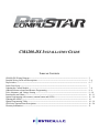
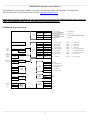
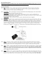
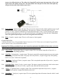
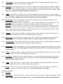
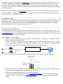
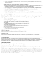
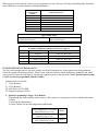
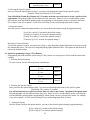
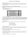
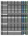
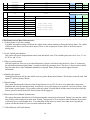
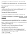
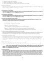
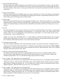
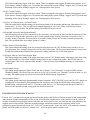
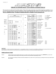
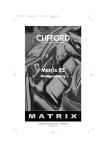
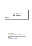
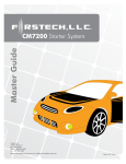
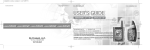
CM4200DX Remote Starter
INSTALL GUIDE
WWW.COMPUSTAR.COM
I.
Button Functions
CM4200-DX INSTALLATION GUIDE
TABLE OF CONTENTS
CM4200-DX Wiring Diagram -----------------------------------------------------------------------------------------Detailed Wiring Guide and Descriptions -----------------------------------------------------------------------------Dip Switches -------------------------------------------------------------------------------------------------------------Little Green Loop -------------------------------------------------------------------------------------------------------Updating the Control Module ------------------------------------------------------------------------------------------Additional Items to Install and Remote Programming -------------------------------------------------------------Tach, Alternator, and Voltage Sensing -------------------------------------------------------------------------------Functionality and Charts -----------------------------------------------------------------------------------------------Option Programming with remotes, antenna button and OP500 --------------------------------------------------Updating the OP500 -----------------------------------------------------------------------------------------------------Option Programming Tables -------------------------------------------------------------------------------------------CM4 Series Option Menu Descriptions -------------------------------------------------------------------------------Warranty Information ----------------------------------------------------------------------------------------------------
2
3–6
6–7
7
7–8
8–9
9 – 10
10 – 11
11 – 14
14
14 – 16
16 – 20
21
________________________________________________________________________________________________
CM4200-DX STARTER CONTROL MODULE
This manual is for professional installers. If you have any questions please call CompuStar Tech Support @
888.820.3690 (8 am to 5 pm Pacific Time) or email: [email protected]
Important Note: Before you make all your wire connections and connect the additional items please review the
Option Programming Tables and the descriptions at the end of this manual.
CM4200-DX WIRING DIAGRAM
1 Red
Key
Sense/Glow
Plug
Polarity
Behavior of
CN1, Pin 2
1: ( + ) 12v Constant
2: ( + ) Parking Light
3: ( + ) 12v Constant Red/Wht
prewired to 2nd Relay
5: ( - ) When Armed prewired to
Anti-Grind Relay
7: ( + ) Ignition Red prewired to
Anti-Grind Relay
6: ( + ) Starter prewired to Anti-Grind Relay
3 Red/Wht
4 White
5 Violet
6 Yellow
7 Gr/Red
8 Black
Jumper
1 Grn/Wht
2 Lt Blue
1: ( - ) Parking Lt. Output
POC #1
2: ( - ) E-Brake Input
Cut=Auto / Uncut=Manual
3 Red/Blk
4 Lt. Blue/Wht
3: ( - ) Starter Output
POC #2
4: ( + ) Brake Input
5 Green
6 Violet/Blk
5: ( - ) Ignition Output
POC #3
6: ( - ) Trunk Input
7 Wht/Blk
8 Red/Wht
7: ( - ) Accessory Output
POC #4
8: ( - ) Door Input
9 Black
10 Brown/Wht
9: ( - ) Status Out (GWR)
POC #5
10: ( - ) Glow Input/Key Sensing
CN1
Door
Trigger
Polarity
2 Gr/Wht
(+)
(-)
CN3
Default
(+)
(-)
Default
( + ) Pk.
Lights
Dip
Switches
11 Orange
12 Dark Org
11: ( - ) Rearm Output
POC #6
12: ( - ) Slave/Timer Start Input
14 Yel/Blk
13: ( - ) Disarm Output
POC #7
14: (AC) Tach / Alternator Input
15 White
16 Gray/Blk
15: ( - ) Horn Output
POC #8
16: ( - ) Hood Input
17 Violet
18 Brown
17: ( - ) Dome Light
POC #9
18: ( + ) Siren Output
None
Future use
Trunk
Release
CN4
4(-)
2 Data
8: ( - ) Ground
13 Org/Wht
Default
3(+)
4: ( + ) Accessory
CN12
RS232
2 Violet/Wht
( - ) Trunk release output
3 Orange/Blk
( - ) Second Unlock Output
4 Blue
( - ) Unlock Output
5 Blue/Blk
( - ) Lock Output
None
( + ) 12v Constant Power
Black
LED ( - )
Black/wht
LED ( + )
1 Data
1 Thermistor
2 Thermistor
( - ) Switch
3 gray
( + ) Led
2 Gray
( - ) Led
1 Gray/Black
CN11
Thermistor
CN9
Plug In
LED/Valet
Switch
CN5
LED
CN8
Antenna
1 Black
(-)
2 White
(+)
3 Red
Tx
4 Yellow
Rx
_______________________________________________________________________________________________
2
_______________________________________________________________________________________________
DETAILED WIRING GUIDE
Important Note: Before you make all your wire connections and connect the additional items please review the
Option Programming Tables and the descriptions at the end of this manual.
CONNECTOR 1 (CN1)
Pin 1 Red - Constant 12-volt (+) positive power input for the control module. This wire must be connected to a
constant 12-volt (+) positive source. The proper wire will test 12-volt (+) positive with the key in the off
position, while key is in the on position and during crank.
Pin 2 Green/White - This is a dual purpose wire that is selectable thru the trunk/light jumper on the control module.
The jumper position will dictate the output of this wire.
Parking light - Parking light (+) positive output. Connect this wire to the (+) positive parking light wire
generally at the parking light switch or behind the fuse box. The proper wire will test 12-volts (+) positive when
the parking light switch is in the on position.
Trunk release - This wire will test 12-volts (+) positive when the trunk release is triggered.
Pin 3 Red/White - Constant 12-volt (+) positive power input for the starter and accessory on-board relays. This wire
must be connected to a constant 12-volt (+) positive source. The proper wire will test 12-volts (+) positive with
the key in the off position, while the key is in the on position and during crank. This pin also has a red/white
wire that is prewired to a relay. The relay also has a short violet wire on pin 85. This is the input from one of the
negative (-) outputs for Ignition, Accessory or Starter on CN3 There is also a long blue wire on pin 30 that
becomes your 2nd Ignition, 2nd Accessory, or 2nd Starter trigger. This diagram explains the purpose of the relay.
Pin 4 White - Accessory 12-volts (+) positive output. This wire must be connected to the heater and A/C blower
motor wire. The proper wire will test 0-volts with the key in the off position, 12-volts (+) positive while key is
in the on position, 0-volts while cranking and back to 12-volts (+) positive with the key in the on position
.
Pin 5 Violet - 250mA (-) negative output when armed and remote started. This wire will provide a (-) negative output
when system is locked and armed and during remote start for anti-grind. (Note: This wire can also be used to
trigger after-market L.E.D. kits and other after-market accessories. Output must be diode isolated when
used to trigger after-market accessories.)
Pin 6 Yellow - Starter 12-volt (+) positive output. This is pre-wired to pin 87a of the starter interrupt relay. This wire
will provide12-volts (+) positive to the vehicle’s starter. The proper wire will test 0-volts with the key in the off
position, 0-volts while the key is in the on position and 12-volts (+) positive during crank. (Note: The vehicle
3
starter wire will need to be cut. The yellow wire from pin 87a on the starter interrupt relay will go to the
starter side of the vehicles starter wire. The yellow/black wire from pin 30 of the starter interrupt relay
will go to the key side of the vehicles starter wire.)
Pin 7 Green and Red - Ignition output and input. This wire must be connected to the vehicles ignition to power up all
accessories and to trigger remote programming. The proper wire will test 0-volts with the key in the off
position, 12-volts (+) positive while the key is in the on position and 12-volts (+) positive during crank. When
the system is armed and you put (+) 12-volts to the Green wire it will trigger the siren and alarm. (Note: Red
wire is the ignition input and pre-wired to the anti-grind/starter kill relay.)
Pin 8 Black - Ground (-) negative input. This wire will connect to chassis ground.
CONNECTOR 3 (CN3)
* Indicates that the wire is a Programmable Output Connector or P.O.C. Please refer to the Option Program Table –
Special Option Group #2 for programmable options.
Important Note: Before you make all your wire connections and connect the additional items please review the
Option Programming Tables and the descriptions at the end of this manual.
Pin 1 *Green/White - Parking light 250mA (-) negative output. This is an optional output that will provide a (-)
negative output with parking light flash.
Pin 2 Light Blue - Parking brake (-) negative input. This input is required for manual transmission reservation mode
and/or to trigger the turbo-timer mode. The proper wire will provide a (-) negative trigger only when parking
brake is set. (Note: Turbo mode is optional.)
Pin 3 *Red/Black - 2nd Starter 250mA (-) negative output. This is an optional output that will provide a (-) negative
output during crank only.
Pin 4 Light Blue/White - Brake 12-volts (+) positive input. This input is required to shut down vehicle when remote
started. The proper wire will test 12-volts (+) positive only when the foot brake is pressed.
Pin 5 *Green - 2nd Ignition 250mA (-) negative output. This is an optional output that will provide a (-) negative
output while the ignition is triggered and during remote start.
Pin 6 Violet/Black - Trunk-pin (-) negative input. This is an optional input that will monitor when the vehicle’s trunk
has been opened
4
Pin 7 *White/Black - 2nd Accessory 250mA (-) negative output. This is an optional output that will provide a (-)
negative output while the accessory output is triggered.
Pin 8 Red/White - Door trigger input. This wire monitors (-) negative or (+) positive trigger door-pins. The proper
wire will provide a (-) negative trigger or a (+) positive trigger only when the doors are opened. You will need
to test the wire for proper polarity and set door dip switch on the control module for the proper polarity. (Note:
This wire is required for manual transmission remote starts.)
Pin 9 *Black - Status 250mA (-) negative output. This is an optional output that will provide a (-) negative output
before the ignition is triggered, during remote start and will shut down after ignition has shut down. (Note: This
wire can be used to trigger factory security and remote start interface modules.)
Pin 10 Brown/White - This is a dual purpose wire that can be programmed in the options menu (Option 4-9) to
monitor the glow plug wire or the key sense wire.
Glow plug - This wire will show a (-) negative or (+) positive trigger while the wait to start light is on. This
wire will delay the starter output to allow the glow plugs to warm up on diesel engine vehicles.
Key sense - This wire will show a (-) negative or (+) positive trigger only when the key is physically in the
ignition. This will prevent the system from setting reservation (manual transmission) or accidental locking
and/or arming if the key is in the ignition. You will need to test the wire for proper polarity and set key/glow
jumper on the control module for the proper polarity.
Pin 11 *Orange - Factory alarm re-arm 250mA (-) negative output. This is an optional output that will provide a (-)
negative pulse output during lock, after crank and after ignition shut down.
Pin 12 Dark Orange - Slave/Timer start (-) negative input. This wire will activate remote start when provided a (-)
negative input. (Note: If vehicle is remotely started, a (-) negative input will turn the vehicle off.)
Pin 13 *Orange/White - Factory alarm disarm 250mA (-) negative output. This is an optional output that will provide
a (-) negative pulse output during unlock and before ignition is turned on.
Pin 14 Yellow/Black - Engine sensing input. A tach input or alternator input is required for the system to sense when
the vehicle is running. (Note: Input signal is selectable thru the option table. No connection is necessary for
voltage sensing.)
Pin 15 *White - Horn honk 250mA (-) negative output. This is an optional output that will provide a 30 or 60 second
(-) negative pulse when the alarm is triggered or during panic.
Pin 16 Gray/Black - Hood-pin (-) negative input. This input is a safety shut down that will prevent the vehicle from
remote starting and shut down the engine when the hood is opened. (Note: This wire will also trigger the
alarm when the system is armed.)
Pin 17 *Violet - Dome light 250mA (-) negative output. This is an optional output that will provide a 30 second (-)
negative output after system is unlocked for dome-light supervision.
Pin 18 Brown - Siren 12-volt (+) positive output. This wire will provide a 30, 60, 120 seconds or 10 pulse for 20
seconds (+) positive output for the external siren. (Note: Factory default is 30 seconds.)
CONNECTOR 4 (CN4)
Pin 1 Not used
Pin 2 Violet/White - Trunk release 250mA (-) negative output. This wire provides a (-) negative trigger pulse. (Note:
Positive trigger trunk release will require a relay. System will unlock doors and disarm alarm prior to
5
trunk release.)
Pin 3 Orange/Black - 2nd Unlock 250mA (-) negative output. This wire is an optional output that will provide a (-)
negative pulse output for driver’s priority door lock. (Note: This feature will require additional relays and
programming.)
Pin 4 Blue - Unlock 250mA (-) negative output. This wire will provide a (-) negative pulse output during unlock and
disarm. (Note: Positive and reverse polarity will require additional relays.)
Pin 5 Blue/Black - Lock 250mA (-) negative output. This wire will provide a (-) negative pulse output during lock
and arm. (Note: Positive and reverse polarity will require additional relays.)
Pin 6 Not used
CONNECTOR 5 (CN5) (Pre-wired L.E.D.)
Pin 1 Black - L.E.D.- (-) negative output.
Pin 2 Black/White-3-volt L.E.D. (+) positive output.
CONNECTOR 8 (CN8) (Pre-wired Antenna Cable)
Pin 1 Yellow - RX input. This wire receives signal from remote.
Pin 2 White - TX output. This wire transmits signal to remote.
Pin 3 Red - 12-volt constant (+) positive input.
Pin 4 Black - (-) negative ground input.
CONNECTOR 9 (CN9) (Pre-wired Valet/Programming Switch)
Pin 1 Gray - (-) Negative valet switch input.
Pin 2 Gray - (+) Positive L.E.D. output.
Pin 3 Gray/Black - L.E.D. (-) negative ground input.
CONNECTOR 11 (CN11) (Pre-wired Thermistor)
This connector is for the new Thermistor which monitors temperature in the vehicle.
Pin 1 Thermistor
Pin 2 Thermistor
CONNECTOR 12 (CN12) (RS 232 Port)
This connector will be used for updating the module and connection to various remote start bypass modules. If you are
unsure which version of the Control Module you have then you should reflash with the most current available. The next
section details this new procedure.
________________________________________________________________________________________________
DIP SWITCHES
The dip switches on this control module are new for the Pro Series.
Switch 1 sets the polarity of input for the red/white door trigger wire on CN3, Pin 8. In the default position switch 1
should be up and set for negative (-) Door Trigger input.
6
Switch 2 sets the polarity of input for the brown/white key sense or glow plug wire on CN3, Pin 10. This switch also
is set in the Option Programming Menu. (Option 4-9) In the default position switch 2 should be down and set for
positive (+) Glow Plug input. When you change Option 4-9 to setting 2 the brown/white wire now becomes a Key
Sense input. This is used to prevent Passive arming or Setting Reservation Mode (Manual Transmission) while the key
is still in the ignition.
Switch 3 controls the output of the green/white wire Connector 1, Pin 2. The switch should be in the down position
and set for positive (+) parking light output. When you change this switch to the up position the parking light output
becomes a positive (+) trunk release wire.
________________________________________________________________________________________________
LITTLE GREEN LOOP
This jumper wire will determine the transmission setting. If the jumper wire is not cut the control module will be set for
manual transmission mode. (Note: The factory default is manual transmission. If the control module is installed in a
manual transmission vehicle and the jumper is cut ALL WARRANTY is void.) When the jumper wire is cut the
control module will be set for automatic transmission mode.
________________________________________________________________________________________________
UPDATING THE CONTROL MODULE
The wiring diagram on the back of the control module should be marked with a “V” at the top. This shows that you
have Version 12. Version 12. If you have any other version, it will be blank or show the version number. Please check
www.compustar.com to download the most current Control Module software. If you do not have a Version 12 or newer
we recommend you update the control module.
How to update the Control Module:
1. You need to have a USB Uploader, the part number CST-USB-ASSY (3 components – a USB cable, a USB
Module and a double head data cable.)
2. You may already have a USB Uploader for the Option Programmer OP500 or iDataLink, order the Y-adapter
data cable, part number USB-DC2. This cable is provided free of charge. The USB-DC2 is an adapter cable that
can flash either the Option Programmer OP500 or any CM4 Series Control Module.
Weblink Updater
Or, for a temporary use, you may modify a CompuStar antenna cable. See the following diagram:
3. Plug in USB connector to available USB port on computer. Do not have anything (idatalink, CM4000, OP500
etc) connected to the updater when connecting it to the computer.
4. Windows will automatically find drivers for the USB upload cable.
5. To retrieve software for updating, please email: [email protected]. Please write “request for update
software” in subject. You can also go to www.compustar.com. Now you are ready to update your control
module
7
6. You will need to first identify what COM port your USB device is set up to use. To do this, Right-click on "My
Computer" and go to "Properties". Once the properties window is on the screen, click the "Hardware" tap at the
top of the window. Then in the main body of the window, click on the Device Manager" button. Under "Ports
(COM & LPT)" There should be a device called "USB Serial Port (COM?)", the number that is in place of the
question mark is your selected com port. Disconnect the main harness; the system can not have power while
you are attempting to update its software.
7. The Secure Valet Switch must be connected.
8. Connect the USB-DC2 or modified cable to the RS232 port of CompuStar.
9. Open the "CM4000 v12" folder, for example, and hold the LED/Valet switch button down while you doubleclick the file that matches your com port. Example: I use COM5 so I would use "Update-COM5.bat". Once the
LED in the LED/Valet switch starts flashing, you can let go of the button. After it is finished, just disconnect
the CM4200-DX from the USB Updater and connect the next CM4200-DX if you have more to do.
________________________________________________________________________________________________
ADDITIONAL ITEMS TO INSTALL
These accessories must be installed and programmed to ensure full functionality of the system.
Important Note: Before you make all your wire connections and connect the additional items please review the
Option Programming Tables and the descriptions at the end of this manual.
Antenna (CN8)
Usually mounted in the top left or center of the front windshield. It can be mounted in any orientation, horizontal or
vertical. Stay at least 1.5 inches away from metal and try to mount below the tint stripe. Once all your Control Module
connections are made and antenna connected you can program the remote(s).
Antenna Cable (CN8)
The antenna cable should be routed to the antenna with care. Try not to pinch or crimp the cable on panels as the
system could experience poor range, poor remote communication or no functionality at all.
Remote Coding Procedure
Once the above wire connections have been made and antenna has been connected, you are ready to program your
remotes. The Control Module can accept up to 3 remotes with the exception of the 2WSSR Pro. The following includes
procedures for programming 1-Way and 2-Way remotes:
1. Cycle the key in the ignition from the “Off” to the “On” position 5 times. This must be done within 7
seconds.
2. After the 5th cycle, you will hear the parking light relay “click” and see the parking lights flash once. Be
aware that the vehicle’s “chime” may prevent you from hearing the relay “click.”
3. Once you hear two relay clicks along with two parking light flashes, the system has just exited remote
coding mode. (Note: If no remotes are programmed at this point then the CompuStar will automatically
enter Valet Mode.)
4. Right after cycling the ignition the 5 times:
a. 1-Way Remote: Tap the lock button on the remote for a split (0.5) second.
b. 2-Way Remote: Tap button I for a split (0.5) second.
c. 2-Way Spread Spectrum Remote – This remote requires a different procedure for programming
I. Remove the (+) positive side of the battery from the remote.
II. Follow steps 1 to 3 above.
III. Slide (+) positive side of remote battery back into remote.
IV. Do not press any buttons on the remote as it is syncing with the antenna.
V. Once the remote receives a page back, the 2WSSR is ready for use.
5. After tapping the button on the remote, you will hear the parking light relay “click” once to indicate that it
has accepted the remote. If you have other remotes you must program them at the same time, repeat steps 4a
or 4b for each remote you have.
8
6. After a few seconds you will hear two relay “clicks” and see two parking light flashes and remote coding
has been completed.
Remote Coding with Secure Valet Switch – Option 3-10, Setting III
To use the Secure Valet Switch you must program Option 3-10, Setting III. The Secure Valet default code is 33.
1. Hold down valet switch for 1.5 seconds. LED on switch will begin to flash rapidly.
2. Tap the button on the switch to enter first number of 2-digit code. LED will flash the first number slowly.
3. Once the LED begins flashing rapidly tap the button on the switch to enter the second number.
4. After the second number is entered the parking lights will flash once
5. Follow step 4 to 5 above.
6. After a few seconds you will hear two relay “clicks” and see two parking light flashes and remote coding
has been completed.
Secure Valet Switch (CN9) Optional
Enables the use of Secure Valet mode, mount where the customer will have easy access. You must program Option 310, Setting III. The Secure Valet default code is 33. Here are the following steps to programming the Secure Valet
code:
1. Turn on Option 3-10-III.
2. Turn key to the ignition on position.
3. Hold down valet switch for 1.5 seconds. LED on switch will begin to
flash rapidly.
4. Tap the button on the switch to enter first number of 2-digit code. LED
will flash the first number slowly.
5. Once the LED begins flashing rapidly tap the button on the switch to
enter the second number.
6. Turn ignition off and Valet Switch is now programmed.
7. To enter valet mode follow steps 3 to 5
LED (CN5) Optional
Bright blue flashing LED used as a theft deterrent, LED output is 3 volts.
Thermistor (CN11)
Senses the current temperature in the vehicle; this item is connected to a port on the back side of the controller.
________________________________________________________________________________________________
TACH PROGRAMMING
Once all your connections are made, accessories installed and programmed and remotes programmed you must
program your Tach/Engine Sensing before you can remote start. Unlike the CM3000 and CM4200, the CM4200-DX
does not have a tach learn button. The following procedure shows how to program tach on the new Pro Series.
Tach learning procedure:
(To test for tach sensing set your digital multi-meter for AC voltage.)
1. Start the vehicle with the key. Allow time for the engine to idle down.
2. At idle the tach wire will test between 1 to 4-volts AC. As the R.P.M.’s increase the voltage on the meter will
increase.
3. While vehicle is at idle, hold the foot brake. While holding the foot brake down press and hold the remote start
button down for 2.5 seconds. The parking lights will flash once and siren will chirp once to confirm the control module
accepted the tach signal. If the parking lights flash three times and the siren chirps three times this is confirmation that
the control module did not accept the tach signal. After two seconds the number of parking light flashes will indicate
the cause of the error. The error codes are as follows:
9
Number of Parking Light
Flashes
1
2
3
Tach Error
Option 2-10 not in default setting 1
Car key in off position
No signal or not fast enough
________________________________________________________________________________________________
ALTERNATOR SENSING
The alternator sensing is alternative engine sensing input. This is not voltage sensing. To use alternator sensing the
engine sense input (yellow/black CN3, Pin 14) must be connected to the stator wire on the alternator. This will be a
small gauge wire.
Alternator sensing procedure
(To test for alternator sensing set digital multi-meter for DC voltage. Alternator sensing is pre-programmed in the
control module and does not require programming. )
1. The stator wire will rest at 0-volts DC while the vehicle is off.
2. Turn the ignition to the run position with the key. The stator wire will test between 4 to 6-volts D.C.
3. Start the vehicle with the key. While the vehicle is running at idle the stator wire will test between 12 to 14volts DC.
________________________________________________________________________________________________
VOLTAGE SENSING – Not Available on Manual Transmissions
This mode reads the vehicle’s battery voltage through the main power wires of the system. During the remote start
process, the system looks for changes in the voltage on CN1 wires. Once the vehicle has started, the voltage on the
main power wire should increase telling the system that the vehicle is now running. Although convenient this is not a
full proof method to remote start vehicles. We recommend tach and alternator sensing before voltage sensing. Voltage
sensing should ease install in the following vehicles:
1. Vehicles with electronic starters.
Some of the newer vehicles, such as, 06 CHEVY EQUINOX, 06 SATURN VUE, 06 SATURN ION, 06 GMC
DENALI, 07 GMC DENALI, 06 CADILLAC ESCALADE, 07 CADILLAC ESCALADE, 06 LEXUS RX330, 06
CHEVY COLORADO, 06 GMC CANYON come with Electronic Starting Systems which determines cranking
time automatically by its own on-board computer upon receipt of an electrical pulse from starter wire.
2. Vehicles in Warm Regions
In the warm regions where the temperature stays above 32º F year round, most vehicles will start successfully with
a 0.6 to 1.5 second starter pulse. Voltage sensing will work with most vehicles in these areas.
NOTE: Vehicles in Cold Regions
In the cold regions where the winter temperature falls below 32º F, the starter cranking time varies from 0.5 to 2 or
3 seconds depending on the engine temperature. In these areas, voltage sensing may fail on some vehicles early in
the morning when the temperature is below 32º F. Voltage sensing may work perfectly on newer vehicles even
under these circumstances. Unfortunately, at this time we do not know what types of vehicles will and will not
work. Our research and development teams will continue working on voltage sensing. With time future versions of
voltage sensing will work in these extreme temperatures.
________________________________________________________________________________________________
FUNCTIONALITY AND CHARTS
Once all your connections are made, remotes programmed and options set you are now ready to test the CompuStar Pro
system. Please refer to the User’s Guide for complete remote functions and instructions. Here are a few charts that
explain the functionality of the CompuStar Pro.
10
When trying to remote start the vehicle you may experience an error. The siren will chirp and parking lights flash three
times followed by a certain amount of parking light flashes:
Number of
Parking Light
Flashes
1
2
3
4
5
6
7
Remote Start Error
Motor running
Key in ignition on position
Door open (manual transmission only)
Trunk open
Foot brake on
Hood open
Reservation off (manual transmission only)
When the vehicle is disarmed, the number of siren chirps indicates which zone has been
triggered while armed.
a) 4 Parking Light flashes and siren chirps –
b) 5 Parking Light flashes and siren chirps –
Optional Sensor triggered.
Shock Sensor triggered.
c) 6 Parking Light flashes and siren chirps – Door, Hood, or Trunk was triggered.
When the system is armed, the LED will blink slowly. When the alarm is triggered,
the number of LED flashes indicate what zone was triggered.
Zone
Situation
LED On Duty
Door/Hood/Trunk/Key
1
2 flash, rest, then repeat
Triggered
2
2nd Shock Triggered
3 flash, rest, then repeat
nd
3
2 Auxiliary Triggered
4 flash, rest, then repeat
4
Panic with remote
5 flash , rest, then repeat
________________________________________________________________________________________________
COMPUSTAR PRO OPTION PROGRAMMING
The Pro Series option menus are the most complex out of the CompuStar line. Some options must be programmed
before the system will function properly. Please review with your customer which options they would like and which
ones you need. Please do not hesitate to contact tech support if you have any questions. (Note: Special Option Groups
1 and 2 can only be programmed with the OP500.)
Options can be set with the:
I. 1-Way Remotes,
II. 2-Way Remotes,
III. ANT-AM or ANT-1WSH
IV. Option Programmer OP500
I. Option Programming Using a 1-Way Remote
Programming the main controller option using a 1-Way remote is a timed process. Please read the instructions
carefully.
1. Selecting the Option Menu
To select a menu, use the following button combinations:
Lock+Unlock for 2.5 sec. then
Lock+Unlock for 2.5 sec.
Lock+Unlock for 2.5 sec. then
Lock+Key for 2.5 sec.
Lock+Key for 2.5 sec. then
Lock+Unlock for 2.5 sec.
11
Menu 1
Menu 2
Menu 3
Lock+Key for 2.5 sec. then
Lock+Key for 2.5 sec.
Menu 4
2. Selecting the Specific Option
Once you select the Option Menu in Step 1 you must scroll through that menu for the specific option.
[Hold the Trunk+Key Buttons for 2.5 seconds]
You will hold the Trunk+Key Buttons for 2.5 seconds each time you want to move down 1 position in the
option menu. The parking lights will also flash and siren chirp once. Pause for a few seconds and the system
will chirp the siren and flash the parking lights corresponding to which option you have selected in the menu.
For example if you select Option 1-10, the siren will chirp 10 times and parking lights flash 10 times.
3. Setting the Option
After the system confirms the option number, you can set the desired option setting by tapping button(s):
[Lock] for a split (0.5) second for the default setting
[Unlock] for a split (0.5) second for optional setting 2
[Trunk] for a split (0.5) second for optional setting 3
[Trunk+Key] for 2.5 seconds for optional setting 4
Resetting to Factory Defaults
To reset the options in a menu, enter the menu. (Step 1) After the parking lights flash and/or siren chirps tap the
Key Button three times. The siren will chirp and parking lights flash three times. The options in that menu will
reset to the default settings.
II. Option Programming Using a 2-Way Remote
Programming the main controller option using a 2-Way remote is a timed process. Please read the instructions
carefully.
1. Selecting the Option Menu
To select a menu, use the following button combinations:
I+II for 2.5 sec. then I+II for
2.5 sec.
I+II for 2.5 sec. then I+IV for
2.5 sec.
I+IV for 2.5 sec. then I+II for
2.5 sec.
I+IV for 2.5 sec. then I+IV for
2.5 sec.
Menu 1
Menu 2
Menu 3
Menu 4
2. Selecting the Specific Option
Once you select the Option Menu in Step 1 you must scroll through that menu for the specific option.
[Tap button 4 for a split (0.5) second]
You will tap button 4 for a split second each time you want to move down 1 position in the option menu.
The parking lights will also flash and siren chirp once. Pause for a few seconds and the system will chirp the
siren and flash the parking lights corresponding to which option you have selected in the menu. For example
if you select Option 1-10, the siren will chirp 10 times and parking lights flash 10 times.
3. Setting the Option
After the system confirms the option number, you can set the desired option setting by tapping button(s):
[I] for a split (0.5) second for the default setting
[II] for a split (0.5) second for optional setting 2
12
[III] for a split (0.5) second for optional setting 3
[IV] for a split (0.5) second for optional setting 4
Resetting to Factory Defaults
To reset the options in a menu, enter the menu. (Step 1) After the parking lights flash and/or siren chirps tap
Button III three times. The siren will chip and parking lights flash three times. The options in that menu will
reset to the default settings.
III. Option Programming Using the ANT-AM or ANT-1WSH Antenna Button
Programming the main controller option using a 1-Way Antenna is a timed process. Please read the instructions
carefully.
1. Turn vehicle’s ignition to the on position.
2. Selecting the Option Menu
To select a menu, use the antenna button:
Hold antenna button until you get 1
chirp/parking light flash.
Hold antenna button until you get 2
chirps/parking light flashes.
Hold antenna button until you get 3
chirps/parking light flashes.
Hold antenna button until you get 4
chirps/parking light flashes.
Menu 1
Menu 2
Menu 3
Menu 4
3. Selecting the Specific Option
Once you select the Option Menu in Step 1 you must scroll through that menu for the specific option. You will
tap the antenna button for a split second each time you want to move down 1 position in the option menu.
Pause for a few seconds and the system will chirp the siren and flash the parking lights corresponding to which
option you have selected in the menu. For example if you select Option 1-10, the siren will chirp 10 times and
parking lights flash 10 times.
4. Setting the Option
After the system confirms the option number, you can set the desired option setting by tapping the antenna
button:
Once for the default setting
Twice for optional setting 2
Three times for optional setting 3
Four times for optional setting 4
Resetting to Factory Defaults
To reset the options in a menu, enter the menu. (Step 2) Hold the antenna button for three seconds. The option
menu will reset and the siren will chirp three times. The options in the other three menus will remain set.
IV. Option Programming Using the OP-500
The OP-500 is required to program options in the Special Option Groups 1 and 2.
1. Connection to Control Module
Using the blue connector on the top of the OP-500, connect it to the control module via the antenna wire. (Use
the included extension cable if necessary.) Once connected, the OP-500 will power up. (The control module
must have 12v+ and ground.)
2. Setting Options in Option Menu and Special Option Groups
13
To change the option number you wish to program, use the left and right arrow keys on the OP-500, it will
scroll through the options available in menu 1 and then move to menu 2, then 3 and 4. At the end of menu 4, if
you have turned on diesel mode or the channel expander, or set any of the auxiliary outputs to “Program”, you
will have the option to program the duration of the diesel timer and/or auxiliary outputs. After the aux and
diesel settings (if selected), the POC options will be displayed. The “POCs” are the programmable outputs on
CN3 of the Pro-Series modules.
You can then use the up and down arrow buttons to adjust the option’s settings. “1” is the default setting, and
“2”, “3”, and “4” are the optional settings. The timing of the aux outputs and of the diesel timer is displayed in
seconds, and the POCs can be set between 0 (default) and 12. If you wish to restore all of the factory defaults,
you can press “R” and “W” until the OP-500 chirps.
3. Finalizing Option Settings to Control Module
When you are done adjusting the various option settings or resetting them to the factory defaults, press and hold
the “W” (write) button until the OP-500 chirps. This will write the settings to the control module. Wait until the
module displays “Success” before disconnecting it from the antenna cable.
Updating the OP-500
This is required only if you have an early version of the Option Programmer OP-500.
1. To retrieve software for updating please email: [email protected]. Please write “request for update
software” in subject. You can also go to www.compustar.com
2. You will need to first identify what COM port your USB device is set up to use. To do this, Right-click on
"My Computer" and go to "Properties". Once the properties window is on the screen, click the "Hardware" tap
at the top of the window. Then in the main body of the window, click on the Device Manager" button. Under
"Ports (COM & LPT)" There should be a device called "USB Serial Port (COM?)", The number that is in
place of the question mark is your selected com port.
3. Connect the USB Updater to the computer, do not have anything (iDataLink, CM4000, OP500 etc) connected
to the updater when connecting it to the computer. After a few seconds, connect the USB Updater to the "USB"
port on the OP500 using the supplied cable. Open the "OP500 v6.2" folder and hold the "W" button on the
OP500 down while you double-click the file that matches your com port.
Example: I use COM5 so I would use "UPDATE-V6-COM5.bat". Once the OP500 displays "UP" on the screen,
you can let go of the "W" button. After it is finished, just disconnect the OP500 from the USB Updater and
connect the next OP500 if you have more to do.
________________________________________________________________________________________________
OPTION PROGRAMMING TABLES
Note: Option Programming, RPS Programming and Secure Valet Programming are available only when the system is
disarmed/unlocked.
Special Option Group #1 and #2 can only be programmed with the Option Programmer OP500.
OPTION GROUP 1
Setting
Applicable To
Feature
Default(I)
Optional(II)
Optional(III)
Optional(IV)
CM4000
CM4200-DX
V
V
V
CM4300
1-1
Unlock before, Lock after, starting.
Off
On
Lock After Remote Start
Only
1-2
Lock / Unlock pulse duration.
0.8 sec
2.5 sec
0.125 sec
V
V
1-3
Driver's priority unlock
Off
On
V
V
V
1-4
Double pulse unlock.
Off
On
V
V
V
1-5
Rearm Output
After Start Shutdown and
First Lock
Locks When Reservation
Mode is Set
After Start Shutdown and
Every Lock
Does Not Lock When
Reservation is Set
V
V
V
V
V
1-6
Reservation Lock (Manual transmission)
14
Reservation Sets 10 Seconds
After the Last Door is Closed
3.5 sec
1-7
Unlock / Disarm With Trunk Release
1-8
Locking while in Passive Arming
Unlock, Factory Disarm, and
Trunk Release
Passive locking w/ Passive
Arming
Factory Disarm, Trunk
Release Only
No Passive Locking w/
Passive Arming
Trunk Release Only
V
V
V
V
V
V
1-9
Ignition controlled door locks
Off
On
RPM Locks (Tach Sensing
Mode Only)
V
V
V
1-10
Auto Relock (If a door is not opened within this
amount of time.)
Off
30 sec
60 sec
5 min
V
V
V
1-11
Ignition / Accessory Out Upon Unlock
Off
Ignition Pulse-same timing as
disarm pulse
Acc Pulse-same timing as
disarm pulse
Ig and Acc Pulse-same
timing as disarm pulse
V
V
V
Default(I)
Optional(II)
Optional(III)
Optional(IV)
CM4000
CM4200-DX
Standard
+0.2 Seconds to Crank Time
+0.6 Seconds to Crank Time
(Voltage Sensing Only)
V
V
1Min
V
V
V
V
V
V
V
V
24 Hour Repeat with Cold
Starting of 2-8
(Runtime 2-7)
V
V
OPTION GROUP 2
Setting
Applicable To
Feature
2-1
Min. Crank Time
2-2
Turbo mode.
Off
2 Min
2-3
Diesel timer.
Wire
3~99sec (10sec Default)
4 Min
2-4
Trigger Start
Off
Single Pulse
2-5
Cold Start with Thermistor Assembly
Off
On
Double Pulse
2-6
Timer Start, or, Minimum Interval Between
Cold Starts
3 Hour (4 minute runtime,
double for Diesel)
1.5 Hour (4 minute runtime,
double for Diesel)
2-7
Remote Start Runtime
15 Min
25 Min
45 Min
3 Min
V
V
2-8
Temperature of Cold Starting
Off
-10° C / 14° F
-5° C / 23° F
0° C / 32° F
V
V
2-9
Temperature of Hot Starting
Off
30° C / 86° F
35° C / 95° F
40° C / 104° F
V
V
No Connection – Voltage
Not for Manual
Transmissions
V
V
V
V
Reservation
(Runtime 2-7)
2-10
Engine Sensing
Tach
Alternator
2-11
Turbo, Remote Start Runtime Extension w/ #1
for 2 seconds
No
Yes
Default(I)
Optional(II)
Optional(III)
CM4300
OPTION GROUP 3
Setting
Applicable To
Feature
Optional(IV)
CM4000
CM4200-DX
V
V
CM4300
3-1
Parking lights While Remote Started
Constant Output
Flashing Output
Off
3-2
Dome Light output
Off
Factory Rearm
45 sec
Factory Rearm + 45 Sec
V
V
V
3-3
Dome Light Delay
Off
5 sec
45 sec
Auto
V
V
V
3-4
Starter-Kill relay.
Anti-Grind
Anti-Grind + Starter Kill
V
V
3-5
Anti-Jacking
Starter-Kill
Ignition-Kill
(no Anti-Grind)
3-6
Factory Alarm Option
Off
On (4200DX Only)
3-7
Siren Duration (Upon Alarm Trigger)
30 sec
60 sec
120 Sec
Chirps for 20 seconds
3-8
Horn Output
On Double Lock Only
On Lock and Unlock
On Lock, Unlock, and Start
On Double Lock and Start
3-9
Horn Output (4000/4300) When Alarm Is
Triggered
3-10
Valet
Pulsed Output
(Horn)
Key 5 times, or Remote
(I+III) while Ignition is On
Constant Output (Secondary
Siren)
Key 5 times or Remote
(I+III)
Secure Valet(Default code
3,3)
Anti-Grind + Passive
Starter Kill
Auto kill
(Auto-door locks Off)
Canadian Remotes w/ AUTO
Function Only
Auto kill
(Auto-door locks On)
Canadian Remotes w/ AUTO
Function Only
V
V
V
V
V
V
V
V
V
V
V
3-11
Channel Expander Mode
Disabled
Enabled
V
V
V
3-12
Passive Arming with Channel Expander
enabled
No Passive Arming
Passive Arming
V
V
V
Default(I)
Optional(II)
Optional(III)
Optional(IV)
CM4000
CM4200-DX
CM4300
OPTION GROUP 4
Setting
Applicable To
Feature
4-1
Aux 1 output
0.5sec
Latch
20 sec
Program
V
V
V
4-2
Aux 2 output
0.5sec
Latch
60 sec
Program
V
V
V
4-3
Aux 1 output Control
By Remote
Arm
Disarm
Panic
V
V
V
4-4
Aux 2 output Control
By Remote
Arm
Disarm
Panic
V
V
V
4-5
Secure Aux Output (1 and 2 Only)
On
Off
V
V
V
4-6
Auxiliary Input 1
Prewarn
Trigger
(-)Disarm
V
4-7
Auxiliary Input 2
Trigger
Prewarn
(-)Arm
V
4-8
Extended Accessory After Ign Shutoff
Off
10 sec
30 sec
4-9
Key Sense or Glow Plug input
Glow Plug Input
4-10
Trigger Start or Closed Loop System Input
Trigger Start input
Until Door Open (1 min max)
V
V
V
V
Key Sense Input
V
V
Closed Loop System Input
V
V
V
V
SPECIAL OPTION GROUP #1
Applicable To
Feature
Setting Value [seconds]
CM4000
CM4200-DX
CM4300
1
Diesel timer
3 ~ 99
V
V
2
AUX1 output time
1 ~ 100
V
V
V
3
AUX2 output time
1 ~ 100
V
V
V
4
AUX3 output time
1 ~ 100
V
V
V
15
5
AUX4 output time
1 ~ 100
V
V
V
6
AUX5 output time
1 ~ 100
V
V
V
7
AUX6 output time
1 ~ 100
V
V
V
8
AUX7 output time
1 ~ 100
V
V
V
SPECIAL OPTION GROUP #2
Applicable To
Feature
Programmable Output Connector
Setting Value
0[Default]
CM4000
CM4200-DX
CM4300
V
1~12
1
POC #1
2nd LIGHT
V
V
2
POC #2
2nd START
V
V
3
POC #3
2nd IG1
V
V
4
POC #4
2nd ACC
V
V
5
POC #5
STATUS
V
V
2nd Light[1],
2nd Start[2],
2nd IG1[3],
2nd Acc[4], Status Out[5], Rearm Out[6],
Disarm Out[7],
Horn Out[8], Dome Light[9],
6
POC #6
REARM
V
V
V
7
POC #7
DISARM
V
V
V
8
POC #8
HORN
V
V
V
9
POC #9
DOME LIGHT
V
V
V
Aux1 Out[10], Aux2 Out[11],
Defrost[12]
________________________________________________________________________________________________
CM4 SERIES OPTION MENU DESCRIPTIONS
1-1 Unlock before, Lock after, starting
If enabled, this option setting will unlock the vehicle before remote starting to disarm the factory alarm. The vehicle
will then relock after it has been remote started. There is also an option to set the vehicle to lock after remote
starting only.
1-2 Lock /Unlock pulse duration
This option will set the output duration on the lock and unlock wires. The available pulse times are 0.8 sec, 2.5 sec,
0.125 sec. and 3.5 sec.
1-3 Driver’s priority unlock
With this option set when you go to unlock/disarm the system it will unlock only the driver’s door. You must tap
the unlock/disarm button again within 3 seconds to unlock the passenger doors. The driver’s door must be isolated
from the other doors. Some additional installation is required. Please contact technical support for more
information.
1-4 Double pulse unlock
Turning this option on will give the unlock wire two pulses during unlock/disarm. This feature can not be used with
option 1-3, drivers priority unlock.
1-5 Rearm Output
This option determines the behavior of the Orange Rearm wire on CN3. It can be set to pulse after remote start
shutdown and when first arming/locking. It can also be set to pulse during every arm/lock. On some vehicles, if the
lock button is pressed again (1-way remotes) after the system is locked/armed, and the rearm wire pulses while the
factory system is already armed, the factory alarm will be triggered.
1-6 Reservation Lock (Manual Transmission)
This option determines the behavior of locking/arming after setting reservation mode. Setting 2 prevents the vehicle
from locking when setting reservation mode. Setting 3 will provide a 10 second delay after closing the drivers door
to allow the user to open another door. 10 seconds after all the doors are closed, if no other door is opened, the
system will shut the motor off, set reservation, and arm the alarm.
1-7 Unlock/Disarm with Trunk Release
16
This option setting will set the unlocking/disarming of the control module during the trunk release through the
remote. Setting 2 keeps the doors locked, disarms the alarm and opens trunk. Setting 3 opens the trunk only.
1-8 Locking while in Passive Arming
This option determines the behavior of the locks during passive arming. After 30 seconds the vehicle will either
lock and arm or not lock and just arm.
1-9 Ignition controlled door locks: Tach sensing mode must be used for this feature to work. You must also turn this
feature on through the remote.
1-10 Auto Relock
If this option is turned on, the system will automatically relock/rearm if the system is disarmed but a door is not
opened. The auto relocking can be set for 30 seconds, 60 seconds, or 5 minutes. For setting 2, the siren will chirp
and parking lights flash every 10 seconds. For setting 3, the siren will chirp and parking lights flash every 20
seconds. For setting 4, the siren will chirp and parking lights flash every 1 minute, 40 seconds. In every instance, on
the third chirp/parking light flash the system will lock/arm.
1-11 Ignition/Accessory Out Upon Unlock
Mostly new dodge vehicles need ign/acc pulse to disarm factory alarm.
2-1 Minimum Crank Time
This option can be used to change the crank times during remote start. Please see the table for more details.
2-2 Turbo mode
This option determines how long the turbo timer runs for to allow the vehicle’s turbo to cool down. The time can be
set to 1, 2 or 4 minutes. The e-brake must be connected to the control module. You must also turn this feature on
through the remote.
2-3 Diesel Timer
The diesel timer allows you to set a wait to start time to allow the vehicle’s glow plugs to warm up. Without setting
this option you must find the vehicle’s wait to start wire. The default time for Setting 2 is 10 seconds. This can be
increased or decreased only with the Option Programmer OP500.
2-4 Trigger start: This option allows the control module to be used as a slave unit. This option determines whether the
slave start wire on CN3 requires a single or double pulse to activate remote start. This can be used on vehicles
where the user would like to keep the factory remote.
2-5 Cold Start with Thermistor Assembly: Turning this option on will turn on the cold/hot start feature. This option
works in conjunction with option 2-6. You must also set the temperatures in options 2-8 and 2-9.
2-6 Timer Start, or, Minimum Interval Between Cold Starts: This option dictates the time interval when the control
module will either remote start or check the temperature and remote start.
Option 1: Will start every 3 hours until the vehicle is remote started or started by key – 4 minute run time.
Option 2: Will start every 1.5 hours until the vehicle is remote started or started by key – 4 minute run time.
Option 3: Will start at the time specified on the 2-Way remote one time for the run time set by Option 2-7.
Option 4: Will start at the specified time on the remote every 24 hours if the temperature falls below as set under 28. For example, if you want your car to start everyday at 7 AM, run for 25 minutes when the temperature of the
inside of the vehicle falls below 32°F, you need to program the following:
1) Option 2-5 (Cold Start) on setting 2
2) Option 2-6 (24 hr. repeat) on setting 4
3) Option 2-7 (25 min run-time) on setting 2
17
4) Option 2-8 (Temp 32°F) on setting 4
5) Set the reservation time at 7 AM (see User’s guide)
6) Turn on Timer Mode on the 2-Way remote. (See Remote User’s Guide)
2-7 Remote Start Runtime
This option sets how long the vehicle will remote start and run for. Default setting 1 is 15 minutes. Setting 2 is 25
minutes. Setting 3 is 45 minutes and Setting 4 is 3 minutes.
2-8 Temperature of Cold Starting
This option sets the temperature at which the vehicle will remote start when setting 2-5 and 2-6 are set. Setting 2 is
-20°C/-4°F. Setting 3 is -15°C/5°F. Setting 4 is -10°C/14°F
2-9 Temperature of Hot Starting
This option sets the temperature at which the vehicle will remote start when setting 2-5 and 2-6 are set. Setting 2 is
30°C/86°F. Setting 3 is 35°C/95°F. Setting 4 is 40°C/104°F.
2-10 Setting Tach/Alternator/Voltage Sensing
There are three engine sensing modes the CompuStar can monitor for remote start. Please see the above Tach,
Alternator or Voltage Sensing sections above for more details.
1. Default setting - Tachometer Wire Sensing
2. Setting 2 - Alternator Wire Sensing
This mode requires a soldered connection to a wire on the alternator.
3. Setting 3 - Voltage Sensing – No Wire Connection, Automatic Transmissions Only.
This mode reads the vehicle battery voltage through the main power wires of the system.
2-11 Turbo, Remote Start Runtime Extension w/#1 for 2 seconds
When you set this option you can reset the run time of either the remote start or turbo timer. To reset the time you
must hold button 1 for 2.5 seconds while the vehicle is remote started or while the turbo timer is running.
3-1 Parking lights while remote started
This determines the behavior of the parking lights during remote start. At default setting the parking lights turn on
solid until the remote start time runs out, vehicle is taken over with the key or remote start is turned off with the
remote. Setting 2 will flash the parking lights during remote start. Setting 3 turns the parking lights off during
remote start.
3-2 Dome Light Output
This option sets the timing output of the Dome Light wire on CN3.
Option 2: Factory Rearm – On this setting, the system pulses the dome light output while locking/arming the
vehicle. Some vehicles need this to arm the factory alarm. (Dome Light On, Lock (Arm), Dome Light Off)
Option 3: 45 Second Dome Light Output – activates the dome light for 45 seconds after the system is disarmed.
Option 4: Is a combination of options 2 and 3.
3-3 Dome Light Delay
This setting gives the control module the ability to ignore the door trigger for the set amount of time. Without this
option set, if the dome light is still on when the vehicle is armed, the remote will show the door open on the LCD
display. On options 2 and 3, if the door trigger is still active after the set time, the car will chirp and or flash the
parking lights 4 times, and the remote will be paged (if a 2-way remote is used) indicating that the door is open.
Option 4: Door trigger will be ignored until the trigger goes away. Only use this mode when necessary, because if
the door is actually left open, you will not be notified.
18
3-4 Anti-Grind/Starter-Kill relay
With this option on the default setting, the starter-kill relay will act as an anti-grind circuit only. It will not disable
the starter when the system is locked/armed. On setting 2, the starter-kill relay will act as an anti-grind and starterkill circuit. Setting 3 is the same as 2, but a passive starter-kill is activated 45 seconds after the vehicle is turned off
or disarmed.
3-6 Factory Alarm Option
With this option turned on, the 4200DX starter only system will function as a factory style alarm by monitoring the
door trigger and sounding the horn and flashing the parking lights if the door is opened after the doors have been
locked. The system will also page the Two-Way remotes.
3-8 Horn Output
The default setting will honk the horn when tapping the lock button twice. This is only available on 1-way remotes.
Optional setting 2 will pulse the horn on lock and unlock. Optional setting 3 will pulse the horn on lock, unlock and
remote start. Optional setting 4 will pulse the horn on double lock and remote start. This will only work on 1-way
remotes.
3-10 Valet
This option changes the way you put the system into valet mode. On default setting you can either cycle the ignition
5 times with the key or turn the ignition on and tap buttons 1+3 or lock+trunk – this is a new feature in 4000 series.
Setting 2 allows you to cycle the ignition 5 times with the key or tap buttons 1+3 or lock+trunk to put the system
into valet mode. – same as CM3000 series.
Setting 3 is a secure valet: The default code is 3, 3 or any number you entered for the RPS unlock code. See page 8
of this manual or the remote user’s guide. You can change the numbers by repeating the following steps and the
first 2 numbers of RPS unlock and secure valet codes overwrite each other.
3-11 Channel Expander Mode
This option requires installation of the Channel Expander module. If you need more than the 2 supplied auxiliary
outputs, you can install the Channel Expander for 5 additional outputs. With this option turned on, POC 9 must be
set to (10) Aux 1 and becomes the data wire that communicates with the Channel Expander. Please see the Channel
Expander instruction manual for more details.
3-12 Passive Arming with Channel Expander Mode
The ability to activate/deactivate Passive Arming through the remote is lost once Channel Expander mode is
activated. If the Channel Expander is being used, set this option to Setting 2 to activate Passive Arming with
Channel Expander Mode. Leave it on the default setting to prevent Passive Arming.
4-1 Aux 1 output – This output must be set through a POC
Through the remote, this option can be programmed for the default setting of a 0.5 second pulsed output. Setting 2
changes the output to a latched setting. The latched output will stay latched until the auxiliary output is activated
again. Setting 3 changes the output of Aux 1 to a 20 second pulse. Setting 4 works in conjunction with the OP500
Option Programmer. With the OP500 you can set Aux 1 to a certain time.
4-2 Aux 2 output – This output must be set through a POC
Through the remote, this option can be programmed for the default setting of a 0.5 second pulsed output. Setting 2
changes the output to a latched setting. The latched output will stay latched until the auxiliary output is activated
again. Setting 3 changes the output of Aux 2 to a 20 second pulse. Setting 4 works in conjunction with the OP500
Option Programmer. With the OP500 you can set Aux 2 to a certain time.
4-3 Aux 1 output Control
19
This option controls the trigger of the Aux output. These are optional event triggers. Default setting triggers Aux 1
by the remote. Setting 2 triggers Aux 1 by remote and arming of the system. Setting 3 triggers Aux 1 by remote and
disarming of the system. Setting 4 triggers Aux 1 through panic of the system.
4-4 Aux 2 output Control
This option controls the trigger of the Aux output. These are optional event triggers. Default setting triggers Aux 2
by the remote. Setting 2 triggers Aux 2 by remote and arming of the system. Setting 3 triggers Aux 2 by remote and
disarming of the system. Setting 4 triggers Aux 2 through panic of the system.
4-5 Secure Aux Output (Aux 1 and Aux 2 Only)
With this option on the default setting you must first tap button 4 on the remote and then tap either button 2 or 3 to
activate Aux 1 or Aux 2. This is to prevent accidental triggering of Aux 1 or 2 if they are hooked up to door
poppers or window modules. On optional setting 2 this turns the secure aux off.
4-8 Extended Accessory After Ignition Shutoff
With this setting you can set the system to keep the Accessory wire powered up after you shut the ignition off. This
can be used to keep the radio powered up for a certain amount of time. Setting 2 keeps the Accessory on for 10
seconds. Setting 3 keeps the Accessory on for 30 seconds. Setting 4 keeps the Accessory on until you open the
door. The maximum time for setting 4 option is 1 minute.
4-9 Key Sense or Glow Plug Input
This option changes the setting of the key sense/glow plug input wire on CN3. Default setting sets the wire as a
glow plug input wire. Setting 2 changes the wire into a key sense input. The key sense input can be used to prevent
setting reservation (manual transmission) and passive arming while the key is still in the ignition.
4-10 Trigger Start or Closed Loop System Input
This option changes the setting of the trigger start input wire on CN3. Default setting is the trigger start when using
the control module as a slave unit. Setting 2 changes the wire into a closed loop system. The wire becomes an
instant trigger if the wire is separated from ground. (-) This can be used for headlights housings or connected to a
tow hitch.
Special Option Group 1
This option group controls the Diesel Timer and Aux 1 though 7. Aux 3 through 7 are only available with the
Channel Expander. The Diesel Timer can only be set for 3 to 99 seconds. Aux 1 through 7 can be set from 1 to 100
seconds. This option group can only be accessed with the OP500 Option Programmer.
Special Option Group 2
This option group controls the Programmable Output Connectors. (POC) The POCs are located on CN3. (please see
wiring guide for more details) This option group can only be accessed with the OP500 Option Programmer. At
default setting each option will read “0.” You can set each POC to 1-12. This changes the function of the POCs.
Please see the option menu and wiring guide for details of each POC.
________________________________________________________________________________________________
LIMITED LIFETIME CONSUMER WARRANTY
Firstech, LLC. warrants to the original purchaser that this product shall be free of defects in material and workmanship
under normal use and circumstances for the period of time that the original owner of this product owns the vehicle in
which it is installed; except that the remote controller unit for the period of one year from the date of installation to the
original owner of this product. When the original purchaser returns the product to the retail store where it was
purchased or prepaid postal to Firstech, LLC., 21911 68th Avenue South – Kent, WA 98032, USA within the warranty
period, and if the product is defective, Firstech, LLC., will at its option repair or replace such.
20
TO THE MAXIMUM EXTENT ALLOWED BY LAW, ANY AND ALL WARRANTIES ARE EXCLUDED BY
THE MANUFACTURER AND EACH ENTITY PARTICIPATING IN THE STREAM OF COMMERCE
THEREWITH. THIS EXCLUSION INCLUDES BUT IS NOT LIMITED TO, THE EXCLUSION OF ANY AND
ALL WARRANTY OF MERCHANTABILITY AND/OR ANY AND ALL WARRANTY OF FITNESS FOR A
PARTICULAR PURPOSE AND/OR ANY AND ALL WARRANTY OF NON-INFRINGEMENT OR PATENTS, IN
THE UNITED STATES OF AMERICA AND/OR ABROAD. NEITHER THE MANUFACTURER OF ANY
ENTITIES CONNECTED THEREWITH SHALL BE RESPONSIBLE OR LIABLE FOR ANY DAMAGES
WHATSOEVER, INCLUDING BUT NOT LIMITED TO, ANY CONSEQUENTIAL DAMAGES, INCIDENTAL
DAMAGES, DAMAGES FOR LOSS OF TIME, LOSS OF EARNINGS, COMMERCIAL LOSS, LOSS OF
ECONOMIC OPPORTUNITY AND THE LIKE. NOTWITHSTANDING THE ABOVE, MANUFACTURER DOES
OFFER A LIMITED WARRANTY TO REPLACE OR REPAIR THE CONTROL MODULE AS DESCRIBED
ABOVE.
Some states do not allow limitations on how long an implied warranty will last or the exclusion or limitation on how
long an implied warranty will last or the exclusion or limitation of incidental or consequential damages. This warranty
gives you specific legal rights, and you may also have other rights, which vary State to State.
Firstech, LLC. is NOT RESPONSIBLE OR LIABLE FOR ANY DAMAGES WHATSOEVER, INCLUDING BUT
NOT LIMITED TO, ANY CONSEQUENTIAL DAMAGES, INCIDENTAL DAMAGES, DAMAGES FOR LOSS
OF TIME, LOSS OF EARNINGS, COMMERCIAL LOSS, LOSS OF ECONOMIC OPPORTUNITY AND THE
LIKE that may or may not resulted from the operation of CompuStar. NOT WITH STANDING THE ABOVE,
MANUFACTURER DOES OFFER A LIMITED WARRANTY TO REPLACE OR REPAIR THE CONTROL
MODULE AS DESCRIBED ABOVE.
Your Warranty
The product’s warranty is automatically void if its date code or serial number is defaced, missing or altered. This
warranty will not be valid unless you have completed the registration card and mailed it to Firstech, LLC. or online
@www.compustar.com within 10 days after purchase to the address listed on the registration card.
21911 68th Avenue South - Kent, WA. 98032
Toll Free: 888.820.3690 – Phone: 206.957.3780 – Fax: 206.957.3330
www.compustar.com
21