1
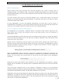
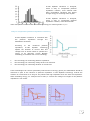
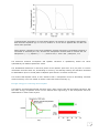
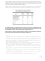
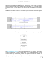
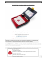
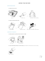
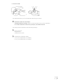
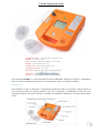
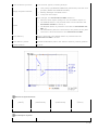
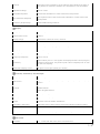
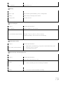
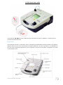
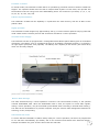
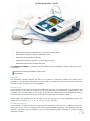
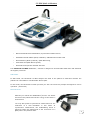
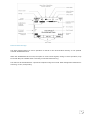
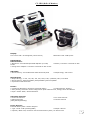
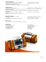
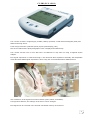
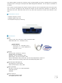
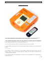
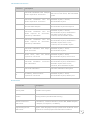
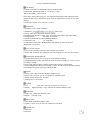
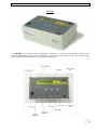
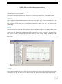
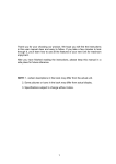
DEFIBRILLATORS JULY - 2008 MEDICAL PRODUCTS DEFIBRILLATORS Quality System Standard applied: ISO 13485:2003 EN46001 MDD 93/42/EEC CE Certification Arsiconsult 38, Av. Guy de Maupassant 78400– Chatou - France Tél. : +33.1.30.53.07.11 Email : [email protected] 1 COMPANY (C) - - - - - - - - - - - - - - - - - - - - - - - - - - - - - - - - - - - - - - - - - - - - - - - - - - - - - - - - - - - - - - - - - - - - - - - - - Page 3 TECHNOLOGY e-CUBE BIPHASIC TECHNOLOGY- - - - - - - - - - - - - - - - - - - - - - - - - - - - - - - - - - - - - - - - - - - - - - - - - - - - - - - - - Page 4 ARRYTHMIA DETECTION - - - - - - - - - - - - - - - - - - - - - - - - - - - - - - - - - - - - - - - - - - - - - - - - - - - - - - - - - - - - - - - -Page 9 DEFIBRILLATORS I-PAD (NF1200) - - - - - - - - - - - - - - - - - - - - - - - - - - - - - - - - - - - - - - - - - - - - - - - - - - - - - - - - - - - - - - - - - - - - - - - - Page 11 CU-ER1 (Single Mode AED) - - - - - - - - - - - - - - - - - - - - - - - - - - - - - - - - - - - - - - - - - - - - - - - - - - - - - - - - - - - - - - - Page 14 CU-ER2 (Dual Mode AED) - - - - - - - - - - - - - - - - - - - - - - - - - - - - - - - - - - - - - - - - - - - - - - - - - - - - - - - - - - - - - - - - Page 20 CU-ER3 (Dual Mode + SpO2) - - - - - - - - - - - - - - - - - - - - - - - - - - - - - - - - - - - - - - - - - - - - - - - - - - - - - - - - - - - - - - Page 22 CU-ER5 (Defb. & Monitor) - - - - - - - - - - - - - - - - - - - - - - - - - - - - - - - - - - - - - - - - - - - - - - - - - - - - - - - - - - - - - - - - Page 24 CU- HD1 (Defb. & Monitor) - - - - - - - - - - - - - - - - - - - - - - - - - - - - - - - - - - - - - - - - - - - - - - - - - - - - - - - - - - - - - - - -Page 27 CARDIOMETER CU-PH1 (ECG MONITOR)- - - - - - - - - - - - - - - - - - - - - - - - - - - - - - - - - - - - - - - - - - - - - - - - - - - - - - - - - - - - - - - - Page 29 CU-PH1 (ECG +SPO2) - - - - - - - - - - - - - - - - - - - - - - - - - - - - - - - - - - - - - - - - - - - - - - - - - - - - - - - - - - - - - - - - - - - Page 32 TRAINER CU-ERT (AED Trainer) - - - - - - - - - - - - - - - - - - - - - - - - - - - - - - - - - - - - - - - - - - - - - - - - - - - - - - - - - - - - - - - - - - Page 34 SIMULATOR CU-SM1 - - - - - - - - - - - - - - - - - - - - - - - - - - - - - - - - - - - - - - - - - - - - - - - - - - - - - - - - - - - - - - - - - - - - - - - - - - - - - -Page 37 DATA MANAGEMENT S/W CU-EX1 (Expert of Data Management Software) - - - - - - - - - - - - - - - - - - - - - - - - - - - - - - - - - - - - - - - - - - - - - - - - -Page 40 2 COMPANY SCI The Company is a high technology company involved in the design, development, manufacture, selling and service of emergency medical devices with the latest IT technology. We provide safe, reliable, and intelligent cardiac monitoring and defibrillation technology that significantly raises access speed to defibrillation. Our mission is for our Paramedic series AEDs to become the standard tool that is fast, effective, and extremely easy to use so that more lives are saved in more places. Aiming at making heart safe The Company a leading medical corporation in the globally connected world of the community, The Company introduced its first brand-new AED in 2002, which was subsequently reviewed and upgraded till 2004. Since the introduction of Paramedic CU-ER1 AED, we have made great strides in putting a lot of importance on the quality of our products and services to encourage the development and adoption of the Paramedic series AEDs by the heart safe community. The Company is now mature and well qualified to meet the needs of the global community. The challenge now with us is to sustain corporate spirits - the competent, challenging, collaborative, clean, credible and contributive business units we have created in the last 4 years and continue to spread the benefits of the heart safe community for patients, customers, and businesses. CORPORATE QUALITY POLICY Since we design, develop, manufacture, sell and service our brand-new Paramedic series AED and other products as well, we put a lot of importance on the quality of our products and services. It is our way of showing to our partners and customers not only our concern for safety and reliability but also our belief that quality is the key for long term success in business. ▣ Do it right the first time to eliminate costly rework ▣ Listen to and learn from customers and employees ▣ Make Continuous improvement an everyday matter ▣ Build teamwork, trust, and mutual respect QUALITY ASSURANCE The Company continuously encourages quality improvement through Total Quality Management to consistently improve the safety and reliability of our products as well as quality systems. With these perspectives, The Company strives to comply with the rigorous quality system regulations of the following organizations: ▣ ISO 13485:2003 (Europe) (with yearly inspections) - EN46001 (Europe) ▣ Medical Device Directive (MDD 93/42/EEC) (Europe) ▣ Community Europe (CE MARK) labelling ▣ KFDA Quality Approval (Korea) ▣ FDA Approval (U.S.) – on processing ▣ JQA Approval (Japan) – on processing 3 TECHNOLOGY e-CUBE BIPHASIC TECHNOLOGY What is Defibrillation? Sudden cardiac arrest (SCA) associated with ventricular fibrillation (VF) remains a leading cause of unexpected death in the Western world. It has been estimated that chances for survival from SCA decrease approximately 7% to 10% with each passing minute and that survival rates after 12 minutes are only 2% to 5%. The most common cause of SCA is ventricular fibrillation (VF), a lethal heart rhythm, and survival depends on the rapid treatment called de-fibrillation, an electrical shock sent to the heart to resume normal and healthy heart rhythm. So early defibrillation is as the sole definitive determinant of survival and is the key factor in cardiopulmonary resuscitation, in the present situation that fewer than 5% of the 250,000 persons who experience out-of-hospital cardiac arrest each year survive to hospital discharge. How E-cube Biphasic waveform Defibrillate? For defibrillation to be successful, a sufficient amount of electrical current must be delivered to the heart muscle. How to deliver the electrical current to the heart muscle is the core technique to defibrillate the heart. Successful defibrillation would be done when the cell membranes of the heart are ―coated‖ with positive ions on one side and negative ions on the other side, enough to depolarize nearly 100 percent of the cardiac cells at the same instant. Optimal current is determined with the pressure (this means electric Voltage) that controls what a amount of current can be pushed and the duration of time the current flows. This defibrillation current is commonly described in joules of energy. Energy is a measure of the amount of current, voltage and duration of time the current flows. Energy (joules) = Current (amps) X Voltage(volts) X Time(sec) When the Defibrillation shock is delivered, current flow is affected by transthoracic impedance, the body’s resistance from electrode to heart. Impedance is dependent on the anatomy of the chest, skin surface, air in the chest, hair, fat and bone, as well as the size and location of the defibrillation electrodes. Current (amps) = Voltage (volts) Resistance (ohms) Research has shown that patient’s chest resistance can vary significantly from patient to patient. Patients with low impedance are generally easier to defibrillate because the flow of current meets little resistance. Those with higher impedance may be more difficult to defibrillate. According to the International Guidelines 2000 by the American Heart Association (AHA) in collaboration with the International Liaison Committee On Resuscitation (ILCOR), average adult impedance is 70-80 ohms. Defibrillation energy should be designed to optimize the delivery of current over a wide range of patient impedances. Too much current to the myocardial cells can cause damage to the cells and result in an unsuccessful defibrillation. Too little current to the myocardial tissue cells will not depolarize the cells and result in an unsuccessful defibrillation. 4 E-cube Biphasic waveform is designed, which is easy to compensate patient’s impedance variance, more efficient than other monophasic waveform and deliver enough energy for restoring heart rhythm. E-cube Biphasic waveform is designed, which is easy to compensate patient’s impedance variance, more efficient than other monophasic waveform and deliver enough energy for restoring heart rhythm. Easy to compensate patient’s impedance variance] E-cube Biphasic waveform is controlled with the patient’s impedance through the defibrillator electrodes. According to the measured patient’s impedance, E-cube Biphasic technology adjusts the duration of current flow and voltage level of electric shock to optimize the energy to be delivered. E-cube Biphasic technology is consisted with 3 core technology. 1. 2. 3. the technology for measuring patient’s impedance. the technology for controlling voltage level to be delivered. the technology for controlling duration of current flow. These technologies can control dynamically what amount of energy (joules) for defibrillation should be delivered in spite of the variance of patient’s impedance. E-cube Biphasic technology controls the duration of current flow to be long for the patient with high impedance than one with low impedance. When escalating energy, for example 150J to 200J, it controls the voltage level higher if the patient’s impedance is not varied. 5 More Efficient than monophasic waveform The electrical therapy delivered by transthoracic cardiac defibrillators has changed little since the introduction of directcurrent defibrillation more than 30 years ago. Throughout this time, the industry-standard shock waveform for external defibrillators has been a monophasic damped sine (MDS)waveform, in which current flows in one direction throughout the shock. Many well-organized emergency medical systems, using monophasic devices for early defibrillation, have documented better than 20% survival to hospital discharge for cardiac arrest patients found in ventricular fibrillation (VF). Attempts to improve this survival rate have adapted proposals to change the waveform and energy level of defibrillation shocks.(6) Biphasic waveform defibrillators incorporate two-way current flow in which Electrical currenat first flows in one direction, then reverses the direction in opposite. Extensive animal and human data with implanted devices demonstrate that biphasic waveforms offer substantial reductions in defibrillation thresholds and produce less myocardial dysfunction than monophasic waveforms.(1-4) The defibrillation efficacy of the 150-J biphasic waveform was superior to that of the 200-J to 360-J conventional escalating-energy monophasic waveforms for 115 patients who presented with VF. (5) 6 Transmembrane potential for a single Beeler-Reuter cell subject to monophasic and biphasic. Each stimulus amplitude (A) is 17.0 mV, duration is 10 ms and is applied 360 ms after the initial action potential. Notice that for a stimulus of the same amplitude, duration and timing, the biphasic stimulus is successful at activating the cell, whereas the monophasic stimulus fails to activate the cell. Monophasic (———); biphasic (−∙−∙−∙−). Keener et al, J. theor. Biol. (1999) 200, 1-17 The difference between monophasic and biphasic waveform is qualitatively similar but varies quantitatively for different parameter values. The fundamental difference is that first phase of the biphasic pulse acts as a pre-pulse to remove inactivation from the heart cell, accelerating its recovery, and thereby lowering the activation threshold for defibrillation prior to second phase of biphasic pulse which is reversed current flow. This means that Biphasic shock is more effective than a monophasic shock at eliminating reentrant electrical activity in an ionic model of cardiac ventricular electrical activity.(7) Enough energy for restoring heart rhythm The Biphasic Truncated Exponential waveform uses a lower energy than the Monophasic waveform. But the lower energy of biphasic shock is more efficient than high energy of the monophasic shock for defibrillation to restore heart rhythm. 7 The high defibrillation efficacy of the particular 150-J impedance-compensating biphasic waveform is observed in the all patients who received treatment with 150-J biphasic shocks were eventually defibrillated during the resuscitation attempt and without resort to backup manual defibrillators, which was not true for the higher-energy monophasic waveforms. Dynamic control of waveform parameters via impedance compensation with a 150-J biphasic shock provides consistently high defibrillation rates without the need for escalating energies 200-J to 300-J The firstshock efficacy of 200-J biphasic shocks is superior to both the 200-J monophasic shocks and the 130-J biphasic waveform shocks. Moreover, the mean peak current was almost 50% lower for the 200-J biphasic shocks than for the less efficacious 200-J monophasic shocks.(6) Positive evidence for safety and clinical effectiveness of biphasic truncated exponential waveforms for internal and external use was ascertained by the AHA ECC committee.(8,9) REFERENCES Chapman PD, Vetter JW, Souza JJ, Wetherbee JN, Troup PJ. Comparison of monophasic with single and dual capacitor biphasic waveforms for nonthoracotomy canine internal defibrillation. J Am Coll Cardiol. 1989;14:242.5. Kavanagh KM, Tang ASL, Rollins DL, Smith WM, Ideker RE. Comparison of the internal defibrillation thresholds for monophasic and double and single capacitor biphasic waveforms. J Am Coll Cardiol. 1989;14:1343.9. Winkle RA, Mead RH, Ruder MA, et al. Improved low energy defibrillation efficacy in man with the use of a biphasic truncated exponential waveform. Am Heart J. 1989;117:122.7. Ruppel R, Siebels J, Schneider MA, Kuck KH. The single endocardial lead configuration for ICD implantation: biphasic versus monophasic waveform [abstract]. J Am Coll Cardiol. 1993;21:128A. T. Schneider, et al. Multicenter, Randomized, Controlled Trial of 150-J Biphasic Shocks Compared With 200- to 360-J Monophasic Shocks in the Resuscitation of Out-of-Hospital Cardiac Arrest Victims. Circulation. 2000;102:1780-1787.) Steven L. Higgins, et al. A comparison of biphasic and monophasic shocks for external defibrillation. Prehospital Emergency Care 2000;4:305.313 J. P. KEENER , T. J. LEWIS. The Biphasic Mystery: Why a Biphasic Shock is More Effective than a Monophasic Shock for De5brillation. J. theor. Biol. (1999) 200, 1-17 AHA, Guidelines 2000 for Cardiopulmonary Resuscitation and Emergency Cardiovascular Care: an international consensus on science. Circulation 2000;102 (Suppl 1). U. Achleitner, et al. Waveform analysis of biphasic external defibrillators, Resuscitation 50 (2001) 61–70 8 ARRYTHMIA DETECTION Sudden Cardiac Arrest is one of the leading causes of deaths in most countries around the world. Coarse Ventricular Fibrillation and Rapid Ventricular Tachycardia are the two primary heart rhythms associated with Sudden Cardiac Arrest. The American Heart Association (AHA) recommends that AEDs should classify Coarse Ventricular Fibrillation and Rapid Ventricular Tachycardia as shockable rhythms [1]. The AEDs manufactured The Company use a proprietary Arrhythmia Detection Algorithm that has been designed to detect Coarse Ventricular Fibrillation and Rapid Ventricular Tachycardia. The algorithm treats all other rhythms as non-shockable. The following figures show Coarse Ventricular Fibrillation and Rapid Ventricular Tachycardia. (Ventricular Tachycardia) (Ventricular Fibrillation) The Arrhythmia Detection Algorithm uses sophisticated Digital Signal Processing techniques to classify the input ECG signals. The following chart shows the overview of the steps done during rhythm classification: The Arrhythmia Detection Algorithm has been validated using Human ECG Databases. The Databases consist of records from the Physionet Physiologic Signal Archives for Biomedical Research and ECG recordings from the ECG database of The Company. The detection tests measure the Sensitivity and Specificity of the Arrhythmia Detector Algorithm. Sensitivity is a measure of the capability of the algorithm to correctly identify shockable rhythms while Specificity is a measure of the algorithm’s capability to correctly identify nonshockable rhythms. 9 The tests using the databases show the following results: Sensitivity Specificity The detector continuously monitors the ECG of the patient as long as the defibrillation pads are connected to the patient. If a patient’s ECG changes from shockable to nonshockable after the AED has charged its defibrillating capacitor, the shock delivery is aborted and the charge is dumped on the internal dump resistance of the AED. REFERENCES Kerber RE, et al. Automatic External Defibrillators for Public Access Defibrillation: Recommendations for Specifying and Reporting Arrhythmia Analysis Algorithm Performance, Incorporating New Waveforms, and Enhancing Safety. A Statement for Health Professionals From the American Heart Association Task Force on Automatic External Defibrillation, Subcommittee on AED Safety and Efficacy. Circulation. 1997;95:1677-1682 ******* The Company is committed to its mission of providing public access life saving devices. The company’s thrusts are: 1. To provide a complete rescue solution, and 2. To incorporate high end features at highly competitive prices. Alongside with its defibrillators, The Company offers a patient simulator for training purposes and a data management software for the archiving, review, and printing of rescue data. Its defibrillators are equipped with features found in more expensive defibrillators from other companies. The AED from The Company features voice and text prompts that guide the user throughout the rescue operation. Rescue operation data is stored in the internal or in the optional external flash memory card. Power is provided by a rechargeable Nickel-Metal Hydride battery 10 DEFIBRILLATORS I-PAD (NF1200) – Intelligence Public Access Defibrillator Size : 220mm X 260mm X 70mm (L X W X H) Weight : Approximately 2.2 Kg Self-Test : Periodic test (daily/weekly/monthly) Battery Insertion Test Battery : 12 Volt DC, 4.2 Ah, lithium manganese dioxide, disposable long-life primary cell Waveform : (impedance compensated) Energy : 200 Joules nominal into a 50Ω load The i-PAD (NF1200) is a semi-automated external defibrillator designed for minimally trained individuals. It provides simple and direct voice prompts and indications for a straightforward rescue operation. It is lightweight and battery powered for maximum portability. The i-PAD(NF1200) is designed to treat Ventricular Fibrillation(VF) and Fast Ventricular Tachycardia(FVT). These two are the most common causes of sudden cardiac arrest (SCA). In SCA, the heart of the victim suddenly stops pumping. This condition occurs suddenly to any age group without any warning. The only effective treatment for VF is the application of a defibrillating shock. Simple operation LED Status Indicators Patented e~cube Biphasic Truncated Exponential shock waveform Automatic self-testing Especially designed for public usage Economic standard package 11 USING THE NF1200 Rescue Preparetion 1. Open the top cover ▶ (open) ▶ (Power on) (Remove of the clothes) 2. Open the disposable pads ▶ (Open pads) ▶ (Take the pads) (Plug of the connector of the pads) Main Rescue Sequence 1. Attach pads on patient then connect to AED ▶ (Peel off) (Attach pads) 2. Press the SHOCK button if instructed (Press button as directed by Voice prompt) (Press button) 12 3. Perform CPR ▶ The NF1200 directs you to do CPR after delivering one shock. Indicators and Voice Prompts - Graphical Rescue Guide: lights up the third step of the rescue operation. - For other indicators and voice prompts, see CPR Protocol The CPR protocol depends on the following settings: Rescue Provider - Lay Rescuer - Healthcare Provider Compression-Ventilation Ratio - 30:2 (30 compressions, 2 breaths) - 15:2 (15 compressions, 2 breaths) 13 CU-ER1 (Single Mode AED) AC Adapter Input : 100-240V AC, 50-60Hz 1.2A Output : +12V DC, 3.5A Size : 305mm X 250mm X 95mm (L X W X H) Weight : Approximately 2.7 Kg Screen Size : 320 x 240 Graphic LCD Galvanic Protection : BF Type Self-Test : Periodic test (daily/weekly/monthly) Waveform : Energy : 150J into a 50Ω load (default setting) The Paramedic CU-ER1 is a semi-automated external defibrillator designed to deliver a defibrillating shock to victims of sudden cardiac arrest. It is designed for easy use and high portability. Easy to Use The Paramedic CU-ER1 is designed to automatically analyze the ECG of the patient. Analysis starts as soon as the ECG pads are properly attached. The user is guided by a combination of text and voice prompts throughout the rescue operation. The ECG of the patient is displayed in a liquid crystal display (LCD). 14 Highly portable The Paramedic CU-ER1 weighs only approximately 2.7 kg. It comes with an optional Carrying Case that could contain all the necessary devices and accessories needed for a rescue operation. Versatile Power Supply The Paramedic CU-ER1 is equipped with a rechargeable Nickel-Metal Hydride battery pack as a standard component. The battery may be recharged through an AC adapter (standard accessory) or through a car cigar lighter jack power cord (optional). The battery has a capacity of 200 shocks when new and fully charged. (Side view of the paramedic CU-ER1) Rescue Data Storage The data collected during a rescue operation is stored in the internal flash memory or the optional external SmartMedia Card. When the SmartMedia card is used, the option to record audio signals during a rescue, operation may be turned ON (not available when recording in internal flash memory). The data can be downloaded to a personal computer using the CU-EX1 data management software for archiving, review, and printing. Automated Self Tests To ensure that the Paramedic CU-ER1 is always ready for a rescue operation, the device is programmed to run self tests automatically (the battery has to be connected and should have sufficient charge). Prompts and alarms are given off if the device fails the self tests. Accessories 15 CU-ER1 TECHNICAL SPECIFICATIONS Physical Category Nominal Specifications Size 3.74 inches high X 9.84 inches wide X 12 inches deep (95 mm high X 250 mm wide X 305 mm deep) Weight Approximately 5.94 lbs (2.7 kg) Environmental Category Nominal Specifications Operating Conditions Temperature 32 °F to 122 °F (0 °C to 50 °C) Humidity 5 % to 95 % (non-condensing) Storage Conditions Temperature -4 °F to 158 °F (-20 °C to 70 °C) Humidity 5 % to 95 % (non-condensing) Shock/Drop/Abuse Tolerance Meets IEC 60601-1 clause 21 (Mechanical Strength) Vibration Meets MIL-STD-810E Method 514.4 Category 10 Sealing Meets IEC 60601-1 clause 44 (Overflow, spillage, leakage, humidity, ingress of liquids, cleaning, sterilization, and disinfection) ESD Meets IEC 61000-4-2:1998 EMI (Radiated) Meets IEC 60601-1-2 limits, method EN 55011:1998 Group 1 Level B EMI (Immunity) Meets IEC 60601-1-2 limits, method IEC 61000-4-3: 1996 Level 2 (3V/m 26MHz to 1GHz) Defibrillator Category Nominal Specifications Operating Mode Semi-automated Waveform (Truncated exponential type); impedance compensated Defibrillator, continued Energy 150J and 180J nominal into a 50Ω load Preprogrammed series 150J-150J-150J 150J-150J-180J 150J-180J-180J Charge Control Automatic by Software (Arrhythmia Detection System and Charging Control) Charge time from ―Shock Advised‖ < 10 seconds, typical 16 Shock to Shock cycle time < 15 seconds, typical, including analysis ☞ Text prompt (CHARGING COMPLETE) followed by text and voice prompts (PRESS THE SHOCK BUTTON) ☞ flashing backlight of SHOCK button Charge complete indicator ☞ beep from the beeper Once charged, the Paramedic CU-ER1 disarms if: ☞ Patient’s heart rhythm changes to non-shockable rhythm, or ☞ The SHOCK button is not pressed within 15 seconds after the Paramedic CU-ER1 is armed, or ☞ The ON/OFF button is pressed to turn OFF the Paramedic CU- Disarm ER1, or ☞ The defibrillator pads are removed from the patient or the pads connector is disconnected from the Paramedic CU-ER1 Shock Delivery Shock is delivered if the SHOCK button is pressed while the Paramedic CU-ER1 is armed. Shock Delivery Vector Via adult defibrillator pads in the anterior-anterior (Lead II) position Patient Isolation Type BF Waveform Specifications Patient Impedance (Ohms) Phase A, Duration (milliseconds) Phase B, Duration (milliseconds) Energy Delivered (Joules) 50 4.4 4.4 150 100 8.5 8.6 150 ECG Analysis System Category Nominal Specifications 17 Function Determines the impedance of the patient and evaluates the ECG of the patient to determine whether it is shockable or non shockable Impedance Range 45Ω to 110Ω Shockable Rhythms Ventricular Fibrillation or Fast Ventricular Tachycardia Non Shockable Rhythms ECG rhythms other than Ventricular Fibrillation or Fast Ventricular Tachycardia Sensitivity & Specificity: Meets AAMI DF39 guidelines Display Category Nominal Specifications Acquired ECG Lead Lead II Display Range Differential ±2mV full scale, nominal Screen Type Liquid crystal display Screen Dimensions 4 inches (10.16 cm) diagonal, 320X240 pixels Sweep Speed 25mm/s, nominal ECG Display 3.2-second segment Frequency Response 1 Hz to 30 Hz Sensitivity Auto-scaled (0.3 to 1 mV signals are displayed with 10mm/mV gain, outside of that range, the peak to peak value is displayed as 10 mm on the LCD display) Heart Rate Display Limits 30 bpm to 300 bpm (beats per minute) Controls, Indicators, and Prompts Category Nominal Specifications LCD Screen High resolution (320X240 pixels), backlighted liquid crystal display screen Controls ON/OFF button SHOCK button Menu Keypad buttons LED Indicators Power, Battery, Error Audio Speaker Provides voice prompts Beeper Provides various audible indications Low Battery Detection Automatic during daily testing and Power ON and runtime testing Low Battery Indicator Battery status indicator icon on the LCD screen Prompts Voice and text prompts guide the user throughout a rescue operation Self-Tests Automatic ☞ Power On Self-Test / Run Time Self-Test 18 ☞ daily / weekly/ monthly User Initiated Manual Self-test Battery Category Nominal Specifications Battery Type Nickel Metal Hydride Battery pack; rechargeable Capacity When newly recharged, 200 shocks Charging time At least 4 hours Storage Temperature -4 °F to 158 °F (-20 °C to 70 °C) AC/DC Adapter Category Nominal Specifications Power Supply 100V to 240V AC, 50 to 60Hz Output 12V DC, 3.5A Environmental Requirements Operating: 32 °F to 104 °F (0°C to 40°C) Storage: -22 °F to 185 °F (-30°C to 85°C) Relative Humidity: 5% to 95% non condensing Conformance Testing EN 60601-1 Defibrillator Pads Category Nominal Specifications ☞ Disposable, self-adhesive, pre-gelled, adult defibrillator pads Pads, Cable, and Connector ☞ Minimum area of 100cm2 ☞ Integrated connector Data Storage and Management SmartMedia Card Memory Category Nominal Specifications Type Removable Flash Memory Card Capacity ☞ 48 hours of Event and ECG recording or ☞ 1 hour recording if voice recording is enabled Internal Flash Memory Type ☞ Flash Memory Capacity ☞ 12 hours of event and ECG recording 19 CU-ER2 (Dual Mode AED) The Paramedic CU-ER2 has all the features of the Paramedic CU-ER1. In addition, a manual mode is provided for advanced users. Easy to Use The Paramedic CU-ER2, in automatic mode, is designed to automatically analyze the ECG of the patient. Analysis starts as soon as the ECG pads are properly attached. The user is guided by a combination of text and voice prompts throughout the rescue operation. The ECG of the patient is displayed in a liquid crystal display (LCD). (The paramedic CU-ER2) 20 Freedom of Choice In manual mode, the Paramedic CU-ER2 has to be operated by personnel trained in advance cardiac life support. The operator should have the skill to interpret ECG rhythms. In this mode, the operator has the freedom to set the energy level of the defibrillating shock. The choices are (in Joules) 2, 3, 5, 7, 10, 20, 30, 50, 70, 100, 150, 200. R Wave Synchronization The Paramedic CU-ER2 has the capability to synchronize the shock delivery with the R Wave of the patient’s ECG. Highly portable The Paramedic CU-ER2 weighs only approximately 2.8 kg. It comes with an optional Carrying Case that could contain all the necessary devices and accessories needed for a rescue operation. Versatile Power Supply The Paramedic CU-ER2 is equipped with a rechargeable Nickel-Metal Hydride battery pack as a standard component. The battery may be recharged through an AC adapter (standard accessory) or through a car cigar lighter jack power cord (optional). The battery has a capacity of 200 shocks (150 Joules each) when new and fully charged. (Side view of the paramedic CU-ER1) Rescue Data Storage The data collected during a rescue operation is stored in the internal flash memory or the optional external SmartMedia Card. When the SmartMedia card is used, the option to record audio signals, during a rescue operation, may be turned ON (not available when recording in internal flash memory). The data can be downloaded to a personal computer using the CU-EX1 data management software for archiving, review, and printing. Automated Self Tests To ensure that the Paramedic CU-ER2 is always ready for a rescue operation, the device is programmed to run self tests automatically (the battery has to be connected and should have sufficient charge). Prompts and alarms are given off if the device fails the self tests. 21 CU-ER3 (Dual Mode + SpO2) AED and Manual Mode Defibrillation, Synchronized Cardioversion, ECG Monitoring Mode (Lead III), SpO2 Monitoring, Heart Rate and SpO2 Alarm System, Lightweight and highly portable, Versatile power supply, Automatic and operator initiated self tests The Paramedic CU-ER3 is a portable semi-automated external defibrillator with the following modes of operation: Automated External Defibrillation (AED) Mode Manual Mode AED Mode The Paramedic CU-ER3 analyzes the ECG of the patient to determine whether the patient has a shockable or nonshockable ECG rhythm. In this mode, the Paramedic CU-ER3 provides you with voice and text prompts throughout a rescue operation. Manual Mode The Paramedic CU-ER3 lets you control the defibrillation process. You assess the ECG of the patient and set the energy of the shock to be delivered. You may also perform synchronous cardioversion for the treatment of a trial fibrillation in this mode. In synchronous cardioversion, the defibrillating shock is delivered within 60 milliseconds of the occurrence of a QRS peak in the patient’s ECG. In this mode, the operator has the freedom to set the energy level of the defibrillating shock. The choices are (in Joules) 2, 3, 5, 7, 10, 20, 30, 50, 70, 100, 150, 200. ECG Monitoring Mode The Paramedic CU-ER3 may also be used to do ECG monitoring only when it is in Manual mode. ECG monitoring only is done by connecting the custom designed ECG monitoring cable assembly from The Company. No shocks may be delivered when the ECG monitoring cable assembly is connected to the 22 Paramedic CU-ER3. The Paramedic CU-ER3 uses two kinds of pads. These are: Multifunction defibrillator pads – used for ECG acquisition and shock delivery. These pads are used during rescue operations. ECG pads – used for ECG acquisition only together with the ECG monitoring cable and connector assembly. The Paramedic CU-ER3 is capable of monitoring pulse oximetry (SPO2, Nellcor) in manual and AED modes. Pulse oximetry measurement is automatically done when the pulse oximetry sensor is connected to the appropriate port on the device. SPO2 Monitoring is indicated when it is beneficial to assess a patient’s oxygen saturation level. Highly portable The Paramedic CU-ER3 weighs only approximately 2.8 kg. It comes with an optional Carrying Case that could contain all the necessary devices and accessories needed for a rescue operation. Versatile Power Supply The Paramedic CU-ER3 is equipped with a rechargeable Nickel-Metal Hydride battery pack as a standard component. The battery may be recharged through an AC adapter (standard accessory) or through a car cigar lighter jack power cord (optional). The battery has a capacity of 200 shocks (150 Joules each) when new and fully charged. Rescue Data Storage The data collected during a rescue operation is stored in the internal flash memory or the optional external SmartMedia Card. When the SmartMedia card is used, the option to record audio signals, during a rescue operation, may be turned ON (not available when recording in internal flash memory). The data can be downloaded to a personal computer using the CU-EX1 data management software for archiving, review, and printing. Automated Self Tests To ensure that the Paramedic CU-ER3 is always ready for a rescue operation, the device is programmed to run self tests automatically (the battery has to be connected and should have sufficient charge). Prompts and alarms are given off if the device fails the self tests. 23 CU-ER5 (Defb. & Monitor) AED and Manual Mode Defibrillation, Synchronized Cardioversion, Reusable External Paddle (Adult, Paediatric) & Multifunction Defib. Pads ECG Monitoring Mode (Lead III), SpO2 Monitoring, Heart Rate and SpO2 Alarm System, Automatic and operator initiated self tests The Paramedic CU-ER5 defibrillator / monitor is designed to accommodate both basic and advanced life support personnel. AED Mode In AED Mode, the Paramedic CU-ER5 analyzes the ECG of the patient to determine whether the patient has a shockable or nonshockable ECG rhythm. In this mode, the Paramedic CU-ER5 provides you with voice and text prompts throughout a rescue operation. (150J Fixed) Manual Mode In Manual External Defibrillation Mode, the Paramedic CUER5 lets you control the defibrillation process. You assess the ECG of the patient and set the energy of the shock to be delivered. You may also perform synchronous cardioversion for the treatment of a trial fibrillation in this mode. In synchronous cardioversion, the defibrillating shock is delivered within 60 milliseconds of the occurrence of a QRS peak in the patient’s ECG. 24 In Manual Internal Defibrillation Mode, the Paramedic CU-ER5 operates as in the Manual External Defibrillation Mode except that the energy is limited to a maximum of 50 Joules and the shock is delivered. Output Energy : 1~10J, 15J, 20J, 30J, 50J, 70J, 100J, 120J, 150J, 170J, 200J) ECG Monitoring Mode In Monitoring Mode, the Paramedic CU-ER5 acquires ECG and SPO2 signals from the patient. Various alarms may be activated in this mode. This mode is also used in tandem with the manual modes in order to get a display of the patient’s ECG rhythm. Lead I, II, III (3-Lead ECG cable) Lead I, II, III, aVR, aVL, aVF or V (5-Lead ECG cable) The Paramedic CU-ER5 automatically records ECG and events such as shock deliveries in nonvolatile memory during rescue operations. These data may be printed directly using a portable printer or downloaded to a personal computer for printing and archiving. The Paramedic CU-ER3 is capable of monitoring pulse oximetry (SPO2, Nellcor) in manual and AED modes. Pulse oximetry measurement is automatically done when the pulse oximetry sensor is connected to the appropriate port on the device. SPO2 Monitoring is indicated when it is beneficial to assess a patient’s oxygen saturation level. Versatile Power Supply The Paramedic CU-ER5 is powered by an internal rechargeable Nickel Metal Hydride battery pack. It may also be powered by an optional external disposable LiMnO2 battery pack or its AC/DC adapter. While the internal battery is being recharged by the AC/DC adapter, the AC/DC adapter also supplies power to the whole device which enables it to be fully functional. Automated Self Tests The Paramedic CU-ER5 runs automatically initiated self-tests even during storage to test its readiness for rescue operations. Faults during these tests are communicated to the user through prompts and alarms. 25 Rescue Data Storage The data collected during a rescue operation is stored in the internal flash memory or the optional external SmartMedia Card. When the SmartMedia card is used, the option to record audio signals, during a rescue operation, may be turned ON (not available when recording in internal flash memory). The data can be downloaded to a personal computer using the CU-EX1 data management software for archiving, review, and printing. 26 CU- HD1 (Defb. & Monitor) Display: TFT Colour LCD 7 inch diagonal (152 X 91mm) Defibrillation: Defib Common: • Waveform: Truncated Exponential Biphasic (E~cube) Joules • Charge time: Adapter: Less than 5 seconds to 200 Joules AED Mode: • Shock Delivery: Via multifunction defib electrode pads Resolution: 800 X 480 pixels • Battery: Less than 7 seconds to 200 • Output Enegy: 200 Joules Manual Mode: • Output Energy: 1~10J, 15J, 20J, 30J, 50J, 100J, 120J, (selected) 150J, 170J 200J • Shock Delivery: External paddle (with paediatric)/Internal paddle • Synchronous Cardioversion Printer: • Continuous ECG Strip: Real-time 8 seconds delay) • Printing Speed: 25mm/s • Auto printing: Recorder can be configured to print marked event, charge, shock and alarms • Paper: 50mm width / 40mm Diameter Automatic Self-test: • Power On self-test • Manual self-test (Daily/Weekly/Monthly) • Run Time self-test • Periodic self test Power Sources: External Battery Pack: Lithium Polymer • Type: 14.8V 3.1Ah (Rechargeable) • Output: 18V 6A • Capacity: When new, minimum 100 shock deliveries (200J) AC Power Pack 27 Non-invasive Pacing: • Waveform: Monophasic Truncated Exponential • Mode: Demand and Fixed Mode • Amplitude Accuracy: 0~200mA (+/- 5mA) • Pulse Width: 20ms (+/- 1.5%) • Pulse Rate: 30~180PPM (+/- 1.5%) • Refractory Period: 340 msec (30-80ppm) 240 msec (90-180ppm) ECG Monitoring: • Input: 3-lead cable: I, II, III 5-lead cable: I, II, III, aVR, aVL, aVF or V 10-lead cable: I, II, III, aVR, aVL, aVF or V1, V2, V3, V4, V5, V6 (display view: All 12 lead ECG waves display simultaneously) • Lead Fault: ―Lead fault‖ message and dashed line display, If an electrode or lea wire becomes disconnected. • Heard rate display: 30-300 bpm (+/- 3bpm) • ECG Size: 5, 10, 20mm/mV and auitogain • Heart rate/Arrhythmia Alarm: HR, Asystole, VF, VT SpO2 Pulse Oximetry: • Sacturation: 70~100% (+/- 3 digits) • Perfusion: 0.2% • SpO2 Alarm: Less than minimum setting rate • Pulse Rate: 20~250 bpm (+/- bpm) • Module Manufacturer: Nellcor ® Over than maximum setting rate Data Storage: • External memory card SD Card (ECG data, Event, Voice) Accessories: • External Paddle • Internal Paddle Adapter • 3 lead ECG Cable • 10 lead ECG cable • SpO2 extension cable • Carrying case • • • • • • Internal Paddle Multifunction defib pads 5 lead ECG Cable SpO2 finger probe Bed hanger Cart bracket 28 CARDIOMETER CU-PH1 (ECG MONITOR) The Cardio Meter CU-PH1 is the highly portable three-lead ECG monitor from The Company. (CU-PH1 Top View) 1. Power indicator Green LED, lit when the device is ON. 2. Power switch Used to turn the device ON or OFF 3. Alarm LED Red LED, flashes when the device detects an ECG signal with beat rate that is beyond the normal range defined by the user. 4. LCD display Displays the following: a. ECG signal acquired from the patient b. ECG signal recorded in the memory of the device c. Menu d. Device settings 5. Left arrow button Used to scroll the menu highlight to the right or downward. This button is also used to turn the QRS beeper ON or OFF 29 6. Menu button Used to activate the menu. When the menu is activated, it is used to select the highlighted menu item 7. Right arrow button Used to scroll the menu highlight to the left or upward. This button is also used to change the Lead of the ECG signal being acquired. Highly Portable The device weighs only 230 g (including the 2 AAA batteries). The user has the choice between chest and hand electrodes. When the hand electrodes are used, the device is capable of acquiring and displaying Lead I ECG only. Multiple Lead Capabilities When the chest electrodes are used, the device can acquire and display Lead I, or II, or III. The switching is done via an internal analog signal multiplexer, thus, there is no need to move the electrodes when switching between leads. Abnormal Heart Rate Alarm The device can be set to give off an alarm when the detected heart rate is beyond the limits defined by the user. ECG Data Recording The ECG data acquired from the patient is automatically recorded in the internal flash memory of the device. This record can be subsequently downloaded to a personal computer using the CU-EX1 data management software from The Company. A total of 600 minutes of ECG record can be stored in the device’s nonvolatile internal flash memory. Heart Rate Trend The device calculates the average heart rate of the acquired ECG every minute and displays the result in a heart rate trend graph. CU-PH1 SPECIFICATIONS • • • • • • • • • • ECG Lead I, II, III with 3 Cable Electrodes Lead I with hand electrodes Bandwidth: 0.3 to 40 Hz ECG Vertical Scales: 5, 10, and 20 mm/mV ECG Sweep speed: 25mm/s ECG Heart Rate: 30 – 300 bpm(± 2%) CMRR: > 90 dB DC offset correction: ± 300 mV Sample resolution: 200 samples/sec, 12 bits Real time monitoring of BPM trend Display • Screen Type: High resolution display (Graphic LCD) • Screen size: 4 inches (10.16 cm) diagonal, 320X240 pixels • Sweep speed: 25mm/sec, nominal 30 • Viewing time: 3.2 seconds • Backlight: Can be turned ON or OFF • QRS Beeping: Can be turned ON or OFF • Screen Information: ECG, Heart Rate, Current Lead(s), Elapsed time, Status of Battery, Alarm, and Recording Data Storage & Management • Recording Time : 600 minutes • Data Recording: ECG Waveform, Recording Time, BPM Trend • Data communication: IrDA Safety Standards • IEC 601-1, IEC 601-2-25, MDD 93/42/EEC • Class IIa Type BF Power • 1.5V x 2 AAA LR03 type batteries • • • • Physical Length: 133 mm Width: 108 mm Thickness: 22 mm Weight: 230 g Package Contents • Device, 1 ECG Cable (3 lead), 2 Battery (1.5V AAA), ECG Electrodes - Optional Accessories Carrying Case ECG Electrodes (50EA/Pack) Data management software (CU-EX1) for patient information Multi-purpose Cradle for the device 31 CU-PH2 (ECG +SPO2) The i-Viewer CU-PH2 is a lightweight, portable, battery operated, 5-lead Electrocardiogram (ECG) and SPO2 monitoring device. It has a high resolution (320x240 pixels) liquid crystal display (LCD). One of the leads and the plethysmographic wave is displayed simultaneously. The i-Viewer CU-PH2 runs on four AAA size 1.5V batteries. It may also run using a supplied AC/DC adapter. ECG signal acquisition is achieved through a five-electrode ECG acquisition assembly with disposable electrodes while SPO2 signal acquisition is done using the recommended Nellcor SPO2 Sensors. User interaction is through three function buttons (LEFT, RIGHT, and MENU). Through these buttons, the settings of the device can be changed. ECG signals can be recorded in the internal nonvolatile memory of the device. 32 The stored signals can later be reviewed. These recorded signals can also be transferred to a personal computer that is running the CU Expert ECG Data Management Software. The CU Expert is available as an option. The i-Viewer CU-PH2 analyzes the signal it acquires from the user and determines the heart rate of the user. The device prompts the user through the beeper and the LED alarm indicator if it detects an abnormal heart rate. Abnormal heart rate is any heart rate beyond the normal limits defined by the user. Convenient to use in - Hospital emergency rooms - Hospital intensive care unit - Pre-hospital emergency monitoring Specification ECG - Lead I, II, III, aVL, aVR, aVF, V with 5 electrode cable. - ECG Heart Rate : 30 ~ 300 bpm (±2%) SpO2 Module - Pulse rate: 20 ~ 250 bpm (±2%) - Saturation: 70 ~ 100% (SpO2±3%) - Perfusion : 0.2% Display - Sweep speed: 25mm/sec. nominal - Viewing time: 3.2 seconds - Backligh : Can be turned ON or OFF - QRS beeping: Can be turned ON or OFF - Screen information: ECG, Heart rate, Current lead, Elapsed time, Status of battery, Alarm and recording, SpO2 value and Plethysmographic wave Data Storage & Management - Recording time: 600 minutes - Data communication: IrDA, UART Safety Standard - IEC 601-1, IEC 601-2-27, MDD 93/42/EEC - Class IIa Type CF - ISO9919 Power Resource - 1.5V AA type batteries 4EA - AC Adapter (DC 12V 3.6A) 33 TRAINER CU-ERT (AED Trainer) The CU-ERT is a defibrillator simulator designed to mimic the operations of the Paramedic CU-ER1. It can simulate all the functions of the Paramedic CU-ER1 including charging and shock delivery. It has preprogrammed rescue scenarios that were generated in accordance with the recommended rescue protocol of international rescue policy making bodies such as the American Heart Association, the European Resuscitation Council, and the American Red Cross. It is to be used in conjunction with the resuscitation mannequin from The Company It has a standard infrared remote control accessory which renders it operable by an instructor from a distance. Intended Use The Paramedic CU-ERT is intended for use during Advanced Cardiac Life Support training, Basic Life Support training, or any other physician approved trainings that deal with the operation of an automated external defibrillator. The Paramedic CU-ERT is not intended for use during actual rescue operations as it cannot deliver a defibrillating shock. 34 10 Standard Scenarios Scenarios Description 1 Shockable rhythm, 3 shocks, 1 minute Ventricular Fibrillation with multiple CPR time-out 4th shock, Non-shockable shocks required for Conversion rhythm 2 Ventricular Fibrillation with shocks required for conversion 3 Non-Shockable Rhythm 4 Shockable rhythm, 2 shocks, Ventricular Fibrillation with two Non-shockable rhythm, Refibrillation shocks required for conversion, -shockable rhythm after 50/sec, followed by refibrillation 3rd shock, Non-shockable rhythm 5 Shockable rhythm, 1 shocks, Ventricular Fibrillation with two Non-shockable rhythm, Refibrillation shocks required for conversion, shockable rhythm after 10/sec, followed by refibrillation 2rd shock, Non-shockable rhythm 6 Ventricular Fibrillation with single- Shockable rhythm, 1 shock, shock conversion Non-shockable rhythm 7 Device Error, with one required for conversion two Shockable rhythm, 2 shocks, Non-shockable rhythm Non-shockable rhythm throughout Shock Shockable rhythm, 1 shock, Non-shockable rhythm, Device Error Shockable rhythm, 1 shock, conversion Non-shockable rhythm, Refibrillation shockable rhythm after 20/sec, 2nd shock, Non-shockable rhythm 8 Ventricular Fibrillation with refibrillation 9 Ventricular Fibrillation Ventricular fibrillation throughout 10 low battery, with one shock required for conversion Shockable rhythm, 1 shock, Non-shockable rhythm, Battery low Accessories Accessories Description Training Pads Reusable training Pads Manikin Training manikin(Included CPR training) Remote Control For AED Trainer 10 Scenarios, 3 Custom Scenarios, Power Off, NSR80 Rhythm, VF Rhythm, VT Rhythm, Low Battery Programming Kit For AED Trainer Support multi language through upload main S/W Edit user's scenarios for certain purpose and add other scenarios 35 CU-ERT SPECIFICATIONS ECG Monitor • Patient connection: Defibrillation Pads, ECG Electrodes • Bandwidth: Monitoring Mode: 0.3 to 40 Hz (-3 dB) AED mode (EMS): 1 Hz to 30 Hz • ECG size: Auto-scaled (0.3 to 1 mV signals are displayed with 10mm/mV gain, outside of that range, the peak to peak value is displayed as 10 mm on the LCD display) • Heart rate: Digital 30 to 300 bpm (± 2%) Defibrillator • Operating mode: Semi automatic • Waveform: (BTE type) • Energy 150J into a 50Ω load (default setting) Preprogrammed selection (150J-150J-150J,150J-150J-180J, 150J-180J-180J) • Charging time: Less than 10 seconds • Sensitivity & Specificity: Meets AAMI guidelines • Detection Level: > 0.1 mV ECG • Defibrillation Electrodes: Multifunction, self-adhesive, adult electrodes (Disposable, Pre-gelled) Voice & Text Prompt • Voice & text prompts guide the user through the protocol • All the user interfaces are supported in local language for easy use and access Data Storage & Management • Internal flash memory:12 hours of event and ECG recording • SmartMedia Card (32M): 48 hours of event and ECG recording or 1 hour if voice recording is enable • Review the patient’s ECG, incident details and the device information • Data management software for storage, review, and printing of multiple patients rescue data using a PC running on Windows OS. • • • • Display Screen Type: High resolution display (Graphic LCD) Screen size: 4 inches (10.16 cm) diagonal, 320X240 pixels Sweep speed: 25mm/sec, nominal Viewing time: 3.2 seconds Physical • Size: 305 mm X 250 mm X 95 mm (L X W X H) • Weight: Approximately 1.4 kg; without the external battery pack AC Adapter • Input: 100 ~ 240V AC 50/60Hz 1.2A • Output: +12V DC, 3.5A Battery Pack • 12V LiMnO2 disposable battery pack • Capacity: when new, 10 hours of continuous operation External Link • UART port • IrDA port 36 SIMULATOR CU-SM1 The CU-SM1 is a battery-powered defibrillator simulator. It outputs simulated ECG rhythms and receives defibrillation shocks from a defibrillator. The CU-SM1 also measures the energy and leading edge voltage of the shock that it receives from a defibrillator. 37 Intended use The CU-SM1 is intended for cardiac rescue simulations during trainings for cardiac emergency responders. The CU-SM1 is not intended for the precise and accurate measurements of defibrillator outputs. The measurement accuracy of the device is not guaranteed when used to measure shocks with energies less than 50 Joules. For shocks with energies between 50 and 200 Joules, the indicated measurement is within 10% of the true value. The maximum voltage and energy that the device can handle are 2000V and 200 Joules, respectively. Even though the shock energy and leading edge voltage measurements are not guaranteed for defibrillation shocks with energies below 50 Joules, the device may still be used in rescue simulations where the delivered shock energy is less than 50 Joules. In this case, the simulated ECG output of the simulator is still useful to the defibrillator. The delivered shock energy measurement, however, has to be discarded. The connector cable that is included with the device is specifically designed for the family of defibrillators from CU The Company. To use the CU-SM1 with defibrillators from other manufacturers, ECG cables fitted with banana connectors will have to be provided by the user. ECG Signal Simulation The CU-SM1 can generate Normal Sinus Rhythm, Ventricular Tachycardia, Supraventricular Tachycardia, Ventricular Fibrillation, fine Ventricular Fibrillation, and Asystole ECG signals. The signal output of the device can be fed to the defibrillators manufactured by The Company to simulate a patient. This is useful during trainings on defibrillator use and testing of defibrillators. Defibrillator Analyzer Function The CU-SM1 can be used to measure the leading edge voltage and the energy output of any defibrillator. Training Mode In training mode, the CU-SM1 switches from a shockable rhythm to normal sinus rhythm after a defibrillating shock is delivered. This is useful in simulating a successful resuscitation. CU-SM1 SPECIFICATIONS Defibrillator Output Energy Measurement Maximum Energy: 200Joules Maximum Voltage: 2000V Accuracy: Energy Measurement: ±10% of actual value (50J to 200J range) Voltage Measurement: ±10% of actual value Load Resistance: 90Ω ±5% ECG Waveforms - Normal Sinus Rhythm Rates: 30, 60, 120, 240 bpm Rate Accuracy: ±1% of selection Amplitude: 1mV peak to peak Amplitude Accuracy: ±5% - Other Waveforms Asystole FVF – fine ventricular fibrillation 38 VF – ventricular fibrillation SVT – supraventricular fibrillation VT138 – ventricular tachycardia, 138 bpm VT180 – ventricular tachycardia, 180 bpm General Power: 9V battery Operating Conditions Temperature: 0°C to 55°C Humidity: 0 to 75% Storage Conditions Temperature: -20°C to 75°C Humidity: 10% to 90% Display: Liquid Crystal Display, alphanumeric, 2 lines, 20 characters Dimensions (width X length X height) : 230mm X 140mm X 85mm Weight: 890g Standard Accessories User’s Manual Defibrillator connector 9V Battery 39 DATA MANAGEMENT S/W CU-EX1 (Expert of Data Management Software) The CU-EX1 is The Company’s data management software intended to facilitate the handling of data recorded during a rescue operation The software has three main functions. These are: a) archiving b) data review, and c) data printing. Archiving The CU Expert manages the downloading of ECG and Rescue Data from devices manufactured by The Company. The supported devices are Paramedic CU-ER1, Paramedic CU-ER2, and Cardio meter CU-PH1. The CU Expert enables the user to enter patient information (Name, Age, Sex, and Address) after downloading. Review The ECG and Rescue Data that have been archived on a personal computer can be opened for review using the CU Expert ECG and Rescue Data Management Software. The software can be set for ECG data review using any of the three available ECG gains. These are 5 mm/mV, 10 mm/mV, and 20 mm/mV. The review is easily controlled through control buttons (PLAY, PAUSE, STOP, BACKWARD, FAST FORWARD). The CU Expert also allows the user to jump to a particular Rescue Event Highlight during ECG review. Printing The CU Expert enables the user to print the ECG waveform and rescue event highlights using a printer connected to the PC. The user has the choice to print the whole record opened, part of the record, or the rescue event highlights only. 40 System Requirements - Hardware/Software Requirements The following hardware and software are needed when transferring data from the Paramedic CU-ER1 to a PC. The user may choose between the UART cable and the IrDA Com-Port Serial Adapter for the data transmission a. Paramedic CU-ER1 b. PC c. CU Expert Version 1.00 S/W d. Device Key File e. UART Cable f. IrDA Com-port Serial Adapter - PC Requirements Operating System Minimum Ram Processor Hard disk Space Free Monitor Capability Color Minimum PC Requirements Windows 98 SE 32 MB Pendium 150Mhz 80 MB 16 bits Windows ME 32 MB Pendium 150Mhz 80 MB 16 bits Windows 2000 64 MB Pendium 150Mhz 80 MB 16 bits Windows XP 128 MB Pendium 233Mhz 80 MB 16 bits Pendium 500Mhz 100 MB 16 bits Recommended PC Setup Windows 2000 XP or 128 MB 41